ISSN(Online): 2320-9801 ISSN (Print): 2320-9798
I
nternational
J
ournal of
I
nnovative
R
esearch in
C
omputer
and
C
ommunication
E
ngineering
(An ISO 3297: 2007 Certified Organization)
Vol. 3, Issue 5, May 2015
A Single Operator Implementation of Task Based
Multiple Unmanned Vehicle
S.Hariprasad, G.Bharathi
PG Scholar, Dept. of ECE, Ranipettai Engineering College T.K Thangal, Tamilnadu, India Assistant Professor, Dept. of ECE, Ranipettai Engineering College T.K Thangal, Tamilnadu, India
ABSTRACT−Automation has greatly reduced operator workload and generally enhanced safety in supervisory control
settings. There has recently been a significant amount of activity in developing supervisory control algorithms for multiple unmanned vehicle operation by a single operator. In the both military and commercial sectors there has been significant research and development in the field of unmanned vehicles. The objective of this paper is use to control multiple UV’s using single operator by RESCHU software. RESCHU (Research Environment for Supervisory Control of Homogeneous Unmanned vehicles) which allows a single operator have the ability to control multiple UVs. This paper approaches two methods namely Vehicle-Based control (where a single operator individually assigns tasks to unmanned assets) and Task-Based control (where the operator generates a task list, which is then given to the group of vehicles that determine how to best divide the tasks among themselves). The proposed framework incorporates (i) sensor constraints, such as processing/travel time, and (ii) task constraints, such as prioritization. These results have implications for the design of future human-UV systems, as well as more general multiple task supervisory control models.
KEYWORDS− RESCHU, UVs, Autonomous, task based, vehicle based
I. INTRODUCTION
In recent years, the use of unmanned vehicles (UVs) has become increasingly prominent. Unmanned aerial vehicles (UAVs), ground vehicles (UGVs), surface vehicles (USVs), and undersea vehicles (UUVs) have been used in applications ranging from military operations toborder security. Unmanned ground vehicles (UGVs) have many potential applications, both in military and civilian areas, such as reconnaissance, surveillance, target acquisition, search and rescue, and exploration. Knowledge of UGV behaviours under control commands on different terrain types plays an important role on improving their safety, reliability and autonomy. In this thesis, the complex process involved in a UGV driveline and its interaction with terrain are thoroughly analysed and a robust low-level control scheme is developed for driving the autonomous vehicle. Mission and path planning makes use of all known information from prior maps, mission goals ,sensory and control structures to generate trajectories, or way points and other actions for the vehicle to execute. However, due to the incomplete knowledge of the world in outdoor missions, the vehicle must use the environment information gathered along the local path to update or rebuild the trajectory. AnUnmanned vehicle car (sometimes called a self-driving car, an automated car or an autonomous vehicle) is a robotic vehicle that is designed to travel between destinations without a human operator with the help of software. To qualify as fully autonomous, a vehicle must be able to navigate without human intervention to a predetermined destination over roads that have not been adapted for its use. Autonomous cars will greatly impact on our lives. They will make driving safer, more convenient, less energy, intensive and cheaper.
II.RELATED WORKS
ISSN(Online): 2320-9801 ISSN (Print): 2320-9798
I
nternational
J
ournal of
I
nnovative
R
esearch in
C
omputer
and
C
ommunication
E
ngineering
(An ISO 3297: 2007 Certified Organization)
Vol. 3, Issue 5, May 2015
for alternative UV.A visualization framework of UAV information constructed from Information Abstraction (IA) was executed.Allowinga single operator to coach a scheduling algorithm resulted in significantly enhanced system performance.The main objective is to control the multiple UV using single operators by novel RESCHU (Research Environment for Supervisory Control of Homogeneous Unmanned vehicles) software. The automation reduces operator workload to control the group of vehicles and the system increases speed as well as efficiency. This also demonstrates the need to incorporate human attention inefficiencies in models of human-UV systems.
III.PROPOSED METHOD
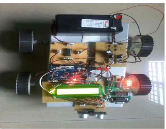
While the literature work has introduced different analyses on different algorithms for both vehicle- and task-based allocation, a key consistent gap has been a lack of direct comparison between the two approaches. This gap raises the following important research question: how does the incorporation of a higher level of automation resource allocation algorithm impact the workload and performance of the operator in both a task-based and vehicle-based paradigm. The software usediscalled Novel Research Environment for Supervisory Control of Heterogeneous Unmanned vehicles (RESCHU), which allows a single operator the ability to control multiple Uvs.The purpose of the project to implement a multiple unmanned vehicle control system using a single operator. The aim of this paper is to reduce the man power with the help of human automation collaboration. There are two sections in this operation. One is the transmitter part and another section is the receiver section. The receiver section consists of the zigbee transceiver and PC and the transmitter section consist of Mini car model, PIC microcontroller and Ultrasonic Sensor, Battery’s.
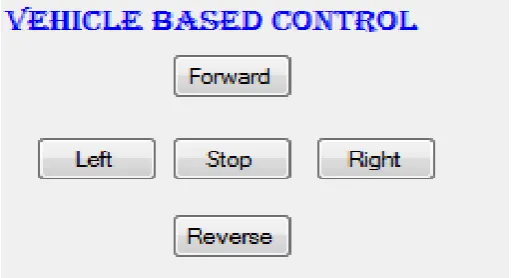
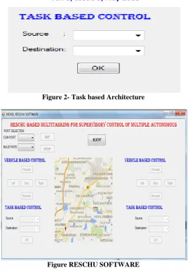
The two methods were analyzed in this project. First method is vehicle based architecture the second method is task based architecture with sensor constraints. In the vehicle based control the user have to handle the each and every steps of vehicle. In vehicle based control the vehicle based architecture the vehicle can able to change the direction. The second method is task based architecture in this method the user have to assign the vehicle to go from source to destination. The vehicles split the best path to go from source to destination. By using this method the vehicle cannot able to stop until it reaches the destination but the vehicle can operated with sensors.
GRAPHICAL USER INTERFACE:
A GUI allows a computer user to move from one application to another application. A good GUI makes an application easier, practical and efficient to use.
ISSN(Online): 2320-9801 ISSN (Print): 2320-9798
I
nternational
J
ournal of
I
nnovative
R
esearch in
C
omputer
and
C
ommunication
E
ngineering
(An ISO 3297: 2007 Certified Organization)
Vol. 3, Issue 5, May 2015
Figure 2- Task based Architecture
Figure RESCHU SOFTWARE
The figure 1 & 2 denotes the Vehicle based control and task based control respectively.
IV. IMPLEMENTATION
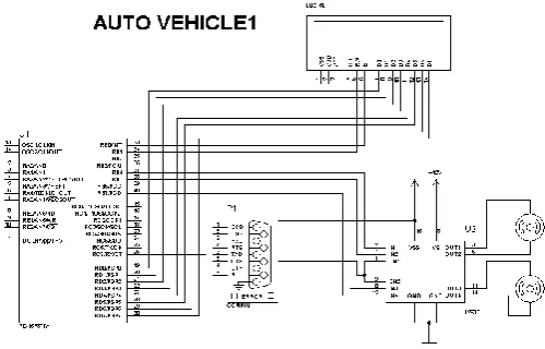
The Unmanned system programming is divided into three main code levels and its hardware was designed with a hierarchical control structure based on modular microcontrollers. The top level program, carried out in C language, is executed in a remote PC and offers to monitor and control the whole robotic vehicle. The second code level, programmed in C language, runs autonomously on a master PIC16F876A microcontroller. Communication with the remote PC is performed by using a ZIGBEE for the centralized control of vehicle and task based.Figure 3 explains about the block diagram of proposed frame work transmitter section. Figure 4 explains about the block diagram of proposed frame work receiver section. Figure 5 gives overall circuit diagram.
Figure 3- Transmitter section
ZIGBEE
PC
ISSN(Online): 2320-9801 ISSN (Print): 2320-9798
I
nternational
J
ournal of
I
nnovative
R
esearch in
C
omputer
and
C
ommunication
E
ngineering
(An ISO 3297: 2007 Certified Organization)
Vol. 3, Issue 5, May 2015
Figure 4- Receiver section
BLOCK DIAGRAM DESCRIPTION
In block PC and GUI are transmitter section, except Zigbee other things are receiver section. Zigbee is acting as a communicating device between transmitter and receiver section. In GUI vehicles are monitored and allow giving instruction from human to Uv.The operator give instructions to PC those instructions will be passed to microcontroller through zigbee in serial communication. Through motor driver the instructions will be transmitted from microcontroller to Dc motor and vehicles will be operated. Ultrasonic sensor will be sensing every time during task based module. So that any object crosses it gives the information to microcontroller. Thenmicrocontroller will stop or else slows the vehicle speed by passing information to DC motor.
Figure 5- Circuit connections
ULTRASONIC SENSOR
BATTERY
PIC
MICROCONTROLLER
DISPLAY UNIT
ZIGBEE MAX 232 MOTOR DRIVER
ISSN(Online): 2320-9801 ISSN (Print): 2320-9798
I
nternational
J
ournal of
I
nnovative
R
esearch in
C
omputer
and
C
ommunication
E
ngineering
(An ISO 3297: 2007 Certified Organization)
Vol. 3, Issue 5, May 2015
ULTRASONIC SENSOR
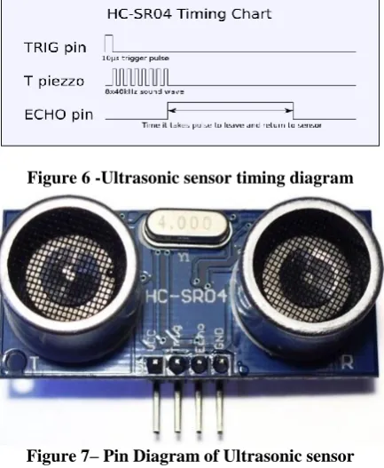
The working of the ultrasonic sensors is quite simple and they are easy to interface with the microcontroller. The sensor module has 4-pins out of which Pin-1 and Pin-4 are +Vcc and Gnd respectively.Pin-2 is Trigger and Pin-3 is Echo pin. The working of sensors can be described from the below figure 6.
Figure 6 -Ultrasonic sensor timing diagram
Figure 7– Pin Diagram of Ultrasonic sensor ZIGBEEMODULE
These modules provide a possibility to build an easy to configure network, with a high data rate up to 230400 Baud/s. To connect XBee module to the microcontroller is done using four wires as shown in fig 8.ZigBee support three types of network topologies: star topology, peer-to-peer topology and cluster-tree topology. The PHY and MAC layers are defined in the IEEE 802.15.4 (IEEE, 2003) standard while the network and application layers are defined in the ZigBee specification.
Figure 8-XBee module interfaced with microcontroller
ISSN(Online): 2320-9801 ISSN (Print): 2320-9798
I
nternational
J
ournal of
I
nnovative
R
esearch in
C
omputer
and
C
ommunication
E
ngineering
(An ISO 3297: 2007 Certified Organization)
Vol. 3, Issue 5, May 2015
V. RESULTS AND DISCUSSION
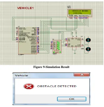
A microcontroller is a small computer on a single integrated circuit containing a processor core, memory and programmable input peripherals built-in used in the wrist strap unit. The PIC microcontroller is programmed using embedded C language for the operation of the above mentioned task in this project.In case of obstacle detected the below message box is shown in Novel RESCHU Software. The figure 9 is the simulation result whereas the Figure 10 is the hardware implementation of this project.
Figure 9-Simulation Result
VI. CONCLUSION
This Research is based on developing the Supervisory controller algorithms for multiple autonomous Vehicles. The previous concept was based on autonomy algorithms. In this paper compares two methods off supervisory control algorithm namely, vehicle based and task based. Both the results was analysed and compared. The Task based control was more efficiency than Vehicle based control. In both control architectures, effectively over relying on the automation to manage the vehicles appropriately the over trusters, while performing the worst in terms of vehicle damage, performed better than the vehicle based performers in terms of number of targets accurately identified. Information is aggregated for presentation, operators can perform well, but this comes at a loss of control and possibly the ability to manage contingencies and unexpected situations.
ISSN(Online): 2320-9801 ISSN (Print): 2320-9798
I
nternational
J
ournal of
I
nnovative
R
esearch in
C
omputer
and
C
ommunication
E
ngineering
(An ISO 3297: 2007 Certified Organization)
Vol. 3, Issue 5, May 2015
TIME ANALYSIS
PERSONS VBA TBA
A 17 10 B 16 10 C 15 10 D 19 10 F 18 10 E 21 12 H 19 10
The damage analysis can be calculated for every 10 vehicles. In vehicle based architecture the damage of vehicle is ratio of every 2 to 3 vehicles in 10 vehicles. In Task based architecture the damage was less when compared to Vehicle based architecture.
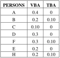
DAMAGE ANALYSIS
PERSONS VBA TBA
A 0.4 0 B 0.2 0.10 C 0.10 0 D 0.3 0 F 0.3 0.10 E 0.2 0 H 0.2 0.10
Figure 11 and 12 represents the Performance analysis & Damage analysis of both Architectures.
Figure 11-Performance Analysis
A B C D F E H
TBA 10 10 10 10 10 12 10 VBA 17 16 15 19 18 21 19
0 10 20 30 40
TIME
IN
SE
C
ISSN(Online): 2320-9801 ISSN (Print): 2320-9798
I
nternational
J
ournal of
I
nnovative
R
esearch in
C
omputer
and
C
ommunication
E
ngineering
(An ISO 3297: 2007 Certified Organization)
Vol. 3, Issue 5, May 2015
Figure 12-Damage Analysis
Figure 10-Hardware Model
REFERENCES
[1] Reuters. US Marines extend K-MAX unmanned helicopter’s use in Afghanistan, May 19, 2013.
[2] T. Chen, D. Campbell, G. Coppin, M. Mooij, and F. Gonzalez, “A capability framework viualisation for multiple heterogeneous UAVS: From a mission commander’s perpsective,” in Proc. 28th Int. Congr. Aeronautical Sci., Brisbane, Australia, 2012, pp. 1–10
[3] C. A. Miller, R. P. Goldman, H. B. Funk, P. Wu, and B. B. Pate, “A playbook approach to variable autonomy control: Application for control of multiple, heterogeneous unmanned air vehicles,” presented at the Am. Helicopter Soc. 60th Annu. Forum, Baltimore, MD, USA, 2004.
[4] M. L. Cummings, C. E. Nehme, and J. W. Crandall, “Predicting operator capacity for supervisory control of multiple UAVs,” in Studies in Computational Intelligence, J. S.Chahk, L. C. Jain,A. Mizutani, andM. Sato-Ilic, Eds. New York, NY, USA: Springer, 2007.
[5] J. S. Bellingham, “Coordination and control of UAV fleets using mixedinteger linear programming,” in Masters, Aeronautics, and Astronautics. Cambridge, MA, USA: MIT, 2002.
[6] A. Caves, “Human-Automation collaborative RRT for UAV mission path planning,” Electrical Engineering and Computer Science, Cambridge, MA, USA: MIT, 2010.
[7] L. F. Bertuccelli and M. L. Cummings, “Operator choice modeling for collaborative UAV visual search tasks,” IEEE Syst., Man, Cybern. A, Syst., Humans, vol. 42, no. 5, pp. 1088–1099, Sep. 2012.
[8] M. L. Cummings, J. How, A. Whitten, and O. Toupet, “The impact of human-automation collaboration in decentralized multiple unmanned vehicle control,” Proc. IEEE, vol. 100, no. 3, pp. 660–671, Mar. 2012.
[9] M. L. Cummings, “Automation bias in intelligent time critical decision support systems,” presented at the AIAA 3rd Intell. Syst. Conf., Chicago, IL, USA, 2004.
0 0.2 0.4 0.6
A B C D F E H