Article
Can a Network Attack Be Simulated in an Emulated
Environment for Network Security Training?
Samuel Chapman, Richard Smith, Leandros Maglaras* and Helge Janicke
School of Computer Science and Informatics, De Montfort University, The Gateway, Leicester LE1 9BH, UK; [email protected], [email protected], [email protected], [email protected] * Correspondence: [email protected]; Tel.: +44-116-207-8483
† These authors contributed equally to this work.
Abstract:This paper outlines a tool developed with the purpose of creating a simple configurable emulated network environment that can be used in cyber defence exercises. Research has been conducted into the various related subject areas: cyber defence exercises, network threats, network emulation, network traffic replay, network topologies, and common network services. From this research a requirements specification was produced to encapsulate the features required to create this tool. A network, containing many of the aspects researched, was designed and implemented using Netkit-NG to act as a blueprint for the tool and to further knowledge in the construction of an emulated network. Following this the tool was developed and tested to ensure requirements were met.
Keywords: Emulation; Network Threat; Network Attack; Network Services; Network Topology; Cyber Defence Exercises
1. Introduction
Computer security is an essential part of keeping an organisation’s data safe from malicious affect. One aspect of computer security is security of a network which is used to ensure networked computers and servers are reliably available to users, and data on these devices is secure. To ensure a network is secure network security experts are required to respond to threats as they appear. These experts are required to be trained in the various aspects of network security and have a strong knowledge base of various network services and how these can be secured [1]. Training experts can take many forms, one method of training is creating cyber defence exercises. These exercises utilise a blue team and a red team. The blue team is tasked with defending and securing a network, whereas the red team’s objective is to attack the network. These exercises do not take place on live networks due to their nature, instead, a network is created with this purpose in mind [2].
Network emulation tools are used to mimic a real network environment, and can therefore be used for cyber defence exercises. These tools have to be configured to specifications created by an end-user, this can be a long process given the possible number of network services required to create a network. This article presents a research that was conducted into cyber defence exercises, network threats, network emulation, network traffic replay, network topologies, and network services. A tool that is capable of creating an emulated network containing the various services found from the research is presented. This tool is capable of mimicking network traffic produced by normal usage of network services, also known as white traffic, in an attempt to obfuscate any malicious network traffic that might be produced in a cyber defence exercise.
The contributions of this article are:
1. Research common network services used in modern organisations and the use of cyber defence exercises (see2.5).
2. Design and implement a virtual network utilising common network services (see3). 3. Add the ability to configure the network based on user requirements (see5).
4. Generate and capture network traffic that simulates normal network usage (see4.1and4.2). 5. Automatically replay captured network traffic (see4.3).
6. Test the system.
7. Randomise the replay of captured network traffic, to further obfuscate any traffic of a malicious nature.
2. Related work
Related work that help ensure the viability of the system proposed in this article, as well as: network emulators, common network threats, the construction of a network, and services that are common throughout networked systems. It takes into account the various aspects required for this system, and aids in making informed decisions regarding the tools and configuration required.
2.1. Cyber Defence Exercises
Cyber defence exercises usually consist of at least two teams, one defending a computer network (blue team) and the other attacking it (red team). This type of exercise is often used for training students and security teams; they also offer an opportunity to see how a team would react if under an actual cyber-attack. The United States National Security Agency (NSA) has been conducting these exercises since 2001 [3]. Both Mullins, and Adams et al. [4] agree that these exercises offer invaluable hands on experience and are an effective method of training people in proper cyber defence, both agree this is because trainees are put in a pressurised environment during the exercise, however Adams takes this further suggesting it is also the element of teamwork inherent to these exercises that makes them truly effective methods of training. The cited authors come from military backgrounds, which could bring into question the reason they strongly approve of cyber defence exercises, however, most of the evidence gathered is from user experience and there are multiple reviewers at these events. Although this type of exercise has been going on for many years there has been little or no previous research into simulated red teams attacking a network.
2.2. Network Threats
A threat is something that has the capability of affecting any part of an organisation in a negative way [5]. The National Institute of Standards and Technology (NIST) are an organisation within the United States Department of Commerce responsible for producing security standards and guidelines for the United States and its definitions are intended for people of different knowledge backgrounds.
2.2.1. Threat Actors
A threat actor isan individual or group posing a threat[5]. Threats can come from a number of different actors, each with different motives and levels of funding. NIST has produced several scenarios where different threat actors are present. However, the SysAdmin, Audit, Network, and Security (SANS) institute and the National Cyber Security Strategy explicitly state what they believe are key threat actors:
• Cyber Criminals - Individuals or groups that attack systems for financial gain.
• States or State Sponsored - Individual or groups funded by governments to attack systems typically used for cyber espionage or to cause damage.
• Hacktivists - Individuals or groups who attack systems for political or moral reasons. • Terrorists - Individuals or groups that attack systems to cause damage to a nation.
• Partner - Trusted partner of an organisation seeking financial gain or a competitive advantage.
Although not all documents agree on each actor they all pose a threat to an organisation or nation. Also, the NIST and United Kingdom’s documentation holds governmental authority, making them viable sources of information even if they do not directly agree on all matters.
2.2.2. Attack Taxonomy
Network attacks can take many forms and taxonomies have been produced by various groups to express these forms. Most of these taxonomies share similarities and it is the common attacks that will be discussed; however, attacks not pertaining to networked systems and attacks utilising human-computer interaction have been deemed irrelevant for the given context. The McAfee threats report [6] has been used in conjunction with the various taxonomies to ascertain how prevalent the types of attack are. This report outlines various statistics of threats detected by McAfee’s various security applications, the figures and statistics of previous versions have been published by a number of media organisations which would not happen if the organisation were accused of skewing their results in a certain direction. While McAfee have a vested interest in selling their products, the figures used show a proportion of an attack type in a given time period rather than the number of the population attacked.
Denial of Service (DOS) is discussed by a number of papers, each with very similar definitions. This type of attack aims to prevent legitimate users accessing network resources [7] by overwhelming the target system with non-legitimate requests. Chapman, [8], in their paper, goes on to discuss a Distributed DOS (DDOS) which utilises a number of computers to overwhelm the target, this is somewhat more sophisticated and is harder to defend as there are many sources of the attack. Although the paper written by Hansman and Hunt is several years old Chapman’s paper shows that the make-up of a DOS attack has not changed in a significant way. In the third quarter of 2016 DOS made up 33% of network attacks which is the largest proportion in the McAfee report. This shows that this type of attack is likely to be seen a lot by network security practitioners.
Brute force attacks made up 18 % of attacks in the third quarter of 2016 showing that they are a significant threat to networks. Chapman describes this type of attack asattempting all possible password combinations. While this type of attack is not particularly sophisticated it poses a clear threat to networked systems. A Domain Name Service (DNS) attack is an attack that aims to send legitimate web users to illegitimate websites. The attacker will pose as a DNS server and then direct users to a fake web page rather than the intended one, this is normally a website which the user has to log in to [9]. This type of attack gives the attacker various user credentials for them to use in a legitimate system. This type of attack made up 4% of the attacks in the third quarter 2016. The information found clearly shows the prevalence of the different types of network attack, this data will be used to produce the attacks featured in the proposed system.
2.3. Network Emulation
Network emulators offer the ability to mimic a network without the need for the requisite equipment, such as cables, routers, server computers, etc. There are many different emulators available, each offering various features to aid the environment creation process. The works of Fuertes and Vergara [10] attempt to measure the resource consumption of several emulators, due to the number of citations of this publication it has been deemed a trustworthy source of data. The emulators chosen for review may have changed functionally since the date of the aforementioned publication, however, this will be taken into consideration.
Netkit
that is not natively available on the virtual machines. The works of Wolny and Szoltysik may be biased, as they discussed Netkit in much greater detail than other software in their overview, they have also stated that Netkit is an available feature in a teaching operating system. Netkit labs can be set up using a set of text files that describe the virtual machines and the desired configuration meaning the labs do not require much storage space per machine which in turn makes it easy to transfer the labs to different machines [12]. It should be noted that Pizzonia and Rimondini are on the team that created Netkit so they are unlikely to have objective views on the subject, that being said, they would be well versed on Netkit’s features. As mentioned previously, Netkit machines use the Debian kernel however, the kernel in use is Debian Lenny which has been deprecated since 2012 It should also be noted that the most recent stable version of Netkit was released in 2011. There is a variation of Netkit called Netkit-NG, this uses a more recent version of the Debian kernel, Debian Wheezy, and was last updated in 2015. Netkit-NG also offers several different features, whilst still being functionally similar to Netkit.
Virtual Network User-Mode Linux (VNUML)
Similar to Netkit, VNUML is an open source emulator, however rather than using a specific kernel VNUML uses the current OSs kernel. Because of this the user has to have elevated privileges for some of the configuration [13]. In order to create a VNUML lab the user must write a file using a variant of eXtended Markup Language (XML) specific to VNUML. The whole lab is contained in a single file, split into two parts; virtual machines (VMs) and virtual networks [14] unlike Netkit which has several files describing each VM. The referenced document was written by the developers of the application; the segment of interest regards features rather that performance statistics or a comparison. VNUML has been superseded by a newer version of the tool called Virtual Networks over linuX (VNX). VNX offers some new features but essentially works in the same way as VNUML, development and maintenance of VNUML has been abandoned.
VMware Server
VMware server is different in comparison to the aforementioned emulation software packages. VMware server can support multiple operating systems in a single network which means you are able to have the Windows OS running on one network node and Linux on another, which allows the user a wider range of network capabilities [15]. Since writing the paper, Li has been cited several times in other papers, however VMware server has been updated since and some of its features have changed in that period. To create a VMware server lab, the user must install the desired operating system on a Virtual Machine (VM) and manually set it up as though it were a stand-alone machine. They must then configure virtual network adapters on the host machine to allow several machines to communicate. When compared to VNUML or Netkit, this could be considered a lengthier setup process, the VM will also be contained within a single folder containing files which cannot be edited while the VM is running. Unlike the previous emulators, VMware has not been changed developers or names and is still maintained today.
Although each emulator is similar they all offer varying functions. VMware Server is somewhat more difficult to setup and configure than the other options although it is able to offer more flexibility in terms of its functions. VNUML and Netkit allow the user to setup VMs using text files or folder structures stored on the host machine, meaning changes can be done without starting the lab. Netkit structures lab configuration using machine specific folders and start-up scripts allowing the user to see at a glance what is going to be emulated. This may be a more appropriate option for creating a pre-configurable network lab.
2.4. Replay of Network Traffic
and destination addresses could be changed to suit the network. This information was taken directly from the maintainer’s website, although they may be biased regarding the utility the description and features are the only items taken from this rather than data regarding its effectiveness. Although the aforementioned website does not discuss Tcpreplay’s performance, tests conducted by Hillstead et al. [16] indicate that the tool is able to reproduce accurate traffic that is produced as and when the user requires.
2.5. Network Topologies
The topology of a network refers to how network nodes are both physically and logically linked. The topology can affect the cost of a network and its integrity, so it should be something carefully considered. To effectively emulate a realistic network, an understating must be established regarding the most common topologies that are currently in use. Network topologies are rarely changed or redesigned therefore there does not seem to be a lot of research in this specific area, however, several books, although dated, have been written which cover basic network topics, the works selected have been cross-referenced with each other in an attempt to ensure information is correct and unbiased.
Mesh
There are four key network topologies, mesh, star, bus, and ring. The mesh topology describes a network where each node is connected to every other node [17]. The connections of a mesh network can be expressed asn(n2−1), although this topology provides a lot of redundancy in the network, it is not particularly practical due to the incurred cost of creating a large number of connections. Duck and Read are the only authors that mention this topology which could be indicative of its real-world capabilities.
Ring
In contrast to mesh the ring topology is made up of nodes that are each connected to two other nodes, logically to their left and right sides. Data travels from one node to another around the ring until it reaches the desired node. If one node in the ring were to malfunction, the entire ring could be disabled. While utilising fewer connections than a mesh, the ring offers far less redundancy which would make it unsuitable for a corporate-style network where continuous operation is a significant consideration.
Bus
The bus topology connects all nodes to a single transmission medium, often depicted as a single wire. While connected, each node will listen on the communications medium and accept data that refers to it specifically. This type of network does not scale well and becomes impractical in large networks due to the number of nodes listening on a single transmission medium. Dean also states that this topology is difficult to troubleshoot and not particularly fault tolerant. There exists an inherent insecurity of a bus due to all nodes having the ability to listen to all messages being transmitted. Considering the disadvantages, the bus topology would not be suitable for a corporate-style network.
Star
A star topology consists of a single central node with all other nodes connected to it. Data will travel through the central node to its destination. Duck and Read discuss the negatives of the star, stating that it requires more connections than the ring or bus, in contrast both Dean and Hodson speak of the benefit of this and how it offers more redundancy than those topologies. Dean also talks about the added flexibility of the star, in that it is simpler to add a new node as there is little chance of it affecting the wider network. There are few networks that use a logical star topology and instead utilise something that is more akin to a bus, this may have been the case in 2003, star with a slight modification, is used in modern networks utilising switches and routers.
Star-Wired Bus
confusing. This topology is the most used topology in the real world. The expandability of this topology makes it the most appropriate choice for a configurable corporate style network.
Common Network Services
Network services give a network various features such as file storage, the ability to produce web pages, email, etc. It is imperative that common services are used to properly emulate a corporate network and the attacks associated with them. A list of widely used services was generated by cross referencing the works of Dean [18], Duck and Read [17], Kurose and Ross [19], and White [20]. To get information about these protocols, their Request For Comment (RFC) pages have been used. An RFC is where a protocol has been defined and informs people in how communications utilising them should look, these are produced by the Internet Engineering Task Force (IETF) who are responsible for producing technical documents regarding internet protocols.
Email is widely used around the world to send messages. There are three key protocols associated with email, Post Office Protocol – version 3 (POP3), Internet Message Access Protocol (IMAP), and Simple Mail Transfer Protocol (SMTP). The SMTP protocol is designed to transfer and deliver mail between two nodes, this is one of the most common protocols for sending an email. IMAP and POP3 are both protocols designed for retrieving mail from a server. Accessing mail on a server is often seen as a cheap solution as it means user’s PCs do not have to have SMTP capabilities in order to receive mail. POP3 is used to download mail from a server directly to a PC. Once it is downloaded, the user is able to read and delete the mail, however, the mail will no longer exist on the server. The IMAP protocol allows users to access the server on which their mail is stored, from there they are able to manipulate it as though it were on their own device, this gives users the ability to access their mail from any device as long as they can access the server. IMAP would be the preferred protocol as it gives users more flexibility with the device they use.
File Transfer
The transfer of files is required by most organisations as a method of sharing and storing data, this process is facilitated by the File Transfer Protocol (FTP). This protocol allows users to share and view data on a remote server. There are variants of FTP which allow a degree of security for file transfers, Secure File Transfer Program (SFTP) and FTP over SSL (FTPS). SFTP is very similar to FTP however it completes all tasks over an encrypted Secure Socket Shell (SSH) channel, the user will connect and then log in to the SFTP server then commence communication. FTP over SSL (FTPS) offers encryption for the FTP protocol using Secure Socket Layers (SSL) or Transport Layer Security (TLS), the use of this encryption must be specified when connecting to the server [21].
Webpages
The Hypertext Transfer Protocol (HTTP) is used for data transfer across the internet, and is commonly used for webpages. A variant of HTTP is Hypertext Transfer Protocol Secure (HTTPS) which uses SSL or TLS to encrypt traffic (Rescorla, 2000) in a similar way to FTPS. DNS is a method used to resolve human readable Uniform Resource Locators (URL) into an Internet Protocol (IP) address, this system is used throughout the internet for web pages and connecting to servers remotely. DNS is also used for addressing email. A database is used that contains both the URL and the IP it refers to, from which the URL can be resolved. This database is updated manually. A similar protocol, known as Dynamic Domain Name System is used for the same end. The key difference is that this system allows for updates to the database that contain the URLs and IP addresses dynamically from the network. DHCP is a protocol that allows the automatic assigning of IP addresses. This is used so new devices do not have to be manually configured to be seen on the network. This is used by organisations as it makes it easier to add new devices to their networks.
Remote Access
to attackers. The SSH protocol works in a similar way to Telnet however it requires users to provide credentials to gain access to the system making it somewhat more secure.
The literature surrounding the subject suggests that an automated system able to simulate network attacks has not before been devised. However, given the benefits of cyber defence exercises, an automated system would be beneficial as it should enable teams to train or learn cyber defence techniques without having to create two different teams: attack, and defence. The literature reviewed has also given indication as to the more prevalent attacks in recent times as well as various protocols that are used in modern day networks. These will all be taken into consideration when constructing the proposed system.
2.6. Key References
There were a number of important sources found during the review of the various literature, these have been reduced to the three considered most influential to the writings. The paper written by Adams et al (2009) regarding cyber defence exercises is very important as it validates the reasons that such exercises have started, for the training of network security teams. Dean’s book (2012) regarding networking was another influential piece of work for this review. It shows what topologies are available to choose from and states, in the author’s opinion, which is best. It also goes on to explain the various networking protocols that are in common use today which was useful as a stepping stone to analysing these protocols. Fuertes and Vergara’s work (2007) outlines the various network emulators that are available, and while this work was written several years ago, it is one of the few that offer a direct comparison of available emulators without discussing possible matters of opinion.
2.7. Paper Discovery Method
The procurement of information regarding this subject was conducted in a specific manner. Firstly, the heading of a section was searched, initially this was done within specific parameters specific parameters: the date was considered, this was confined to papers written after 2005 to ensure current validity of data, the most recent papers were considered first; the number of citations was looked at in an effort to determine impact within the research area. These search terms were not binding however as this was sometimes inappropriate, for example the use of the RFC pages insubsection 2.5was deemed acceptable, although these pages could be considered dated, as these were the documents that defined the protocols making them a very relevant source. The title of a document was then looked at to determine relevance to the subject area, the abstract of the document was looked at in the same manner. Once this had been done, the papers were read in more detail and the content used where appropriate.
3. Network Overview
The network has been implemented in a Netkit environment and includes many of the services discussed in the literature review (seesubsection 2.5). A summary of this network is provided however a more in depth technical explanation, of both the network setup and Netkit-NG setup, has been provided. The topology used mimics that of a star-wired bus, see2.5, as it was decided from the various literature that this was the most suitable for a network attempting to mimic that used in a corporate environment. 1(see1) shows the network in this topology with the various nodes that appear on it. This network has been split into several collision domains, which act as the different areas of the topology.
3.1. Collision Domain: TAP
that this feature should be implemented to allow the network to better produce traffic by interacting with the internet.
3.2. Collision Domain: D
Collision domain D contains the routers of the network. These routers allow network traffic to be transported throughout the other collision domains. As well as routing, the nodes on this collision domain act as DHCP relays, by utilising the ISC-DHCP-Relay tool. This allows them to forward DHCP packets from the DHCP server on collision domain A to the nodes on their subnet.
3.3. Collision Domains: B & C
Collision Domains B and C contain remote PCs. These nodes do not utilise any servers and are used to simulate standard network nodes without special function. Netkit-NG does not have a web browser installed by default so this has to be done when the remote PCs initially start-up, this is scripted so that the user does not have to do this, nor does the user require an internet connection for this. The web browser chosen was Links as this is an easy to use browser that can operate in the Linux terminal. Pine, an email client, is also used on these nodes. This is a simple text based mail client which allows users to view and send emails. This was chosen as it requires little configuration to function and it is possible to use without a graphical interface. To give users individual mailboxes, several accounts were created on the email server, which are logged into when Pine is started on the remote PC.
3.4. Collision Domain: A
Collision domain A contains all of the servers for the network, documentation for the setup procedures of this collision domain has been provided. The servers were placed on the same collision domain to make the setup process easier and to make the network simpler to understand to those that need to use it.
FTP Server
The FTP server daemon used is ProFTPD, this was chosen for a variety of reasons. ProFTPD is available on Netkit-NG, this means that there is no requirement to script its installation therefore reducing its time to start-up. It is also possible to configure FTP, SFTP, and SFTP, using this server daemon which offers a level of convenience during network setup. Several user accounts have been set up on this server to allow login when a connection is established.
SFTP Server
The SFTP server is set up in the same way as the FTP server; however, it uses SFTP to ensure a higher level of security on the server. After some testing it was found that ProFTPD was unable to run FTP and SFTP server concurrently, it was therefore decided that they should run on separate nodes.
HTTP Server
The HTTP protocol has been implemented via the apache daemon. Like ProFTPD this was already installed on Netkit-NG so using this was the preferred choice to reduce network start-up time. This daemon also offers HTTPS functionality which has been implemented on the same node. Whether to have a separate HTTPS node was considered, however, to include both HTTP and HTTPS on the same node had no foreseeable drawbacks and helped to consolidate services making the network as a whole easier to understand.
Email Server
given scenario, POP3 capabilities did not take any more time to implement in exim4 and allow the user to use this if it is required. OpenBSD-inetd has been used to direct any traffic, that uses POP3 or IMAP, coming to the user to the imapd and ipop3d programs. These programs are open source and enable access to the mailbox directory on the email server. OpenBSD-inetd was chosen as it is simple to direct specific traffic to an application. The imapd and ipop3d programs were used as they do not require installation to use, thus cutting start-up time. They also do not require much configuration.
DHCP Server
The daemon chosen to implement DHCP was ISC-DHCP-Server. This daemon was chosen as the configuration files are easy to read and understand, provided there is already knowledge of the DHCP protocol. This daemon needed to be installed via a script as it did not come pre-installed with Netkit-NG. There is a daemon already installed on Netkit-NG that is capable of handling DHCP, dnsmasq (seesubsection 3.4).
DNS Server
Bind9 was implemented as the DNS server for the network. This server comes installed on Netkit-NG so there was no need to install this on start-up. The Bind9 daemon was used due to personal familiarity with its setup and configuration. Rather that utilising standard DNS, where each device would have to be manually configured within the chosen daemon, the network here uses Dynamic DNS (DDNS). DDNS allows for address assignment as nodes appear on the network, it also allows devices with non static IP addresses to be assigned host names and communicate this way which reduces the need for remembering a large number of IP addresses.
Critical Analysis
Although most of the services described in the literature are available in the designed network, some were not included. SFTP is not available to the network. This was due to difficulties in its initial setup. It was possible to configure an HTTPS server which uses technology similar SFTP it was more difficult to implement this with ProFTPD.
As mentioned in3.4the DHCP daemon native to Netkit-NG was not used. ISC-DHCP-Server was chosen over dnsmasq as it requires less configuration to enable DDNS whilst using separate DHCP and DNS servers. Using separate DHCP and DNS servers offers users more options when using the network as they can choose not to use the DNS server entirely, this was an option not found when using dnsmasq. ISC-DHCP-Server also works slightly better with the ISC-DHCP-Relay daemons utilised in the routers in collision domain D.
3.4.1. Network Decisions
Figure 1.A diagram of the implemented network.
4. Network Traffic Replay
This section gives an overview of how network traffic was produced and replayed across the network. Once the network was built, network traffic could then be produced; this traffic would then be captured and used to create white traffic on the network. This is done to make it more difficult to distinguish normal network traffic from that of a threat actor.
4.1. Creation of Network Traffic
Creating network traffic involved using the servers created previously (see3). These services were used on theremotenodes, as they are designed to mimic a non-server device which would use the available services. Creating network traffic involved using the various services available on the network. For example, to generate email traffic, several emails were sent using theremotenodes (see 3.3). This process was repeated in a similar manner for FTP, SFTP, SSH, HTTP, and HTTPS in that the services were simply used to generate the traffic. The DHCP service will automatically function when it is needed by the network, as this is one of its key functions. Equally, the DNS service would be used as required by the network, and when such traffic was produced for DNS as the above services were used. Similar to the DNS service, the routers direct traffic based on network usage and, as such, were used in the production of traffic.
4.1.1. Creation of Internet Traffic
moz.com, and similarweb.com (n.d.). Three different lists were used as each claim to use several techniques to gather website usage data. The second criteria was whether log in credentials were required to access the website, this simply ensures that no private details would appear when the traffic was captured. The final criteria was whether the website could be displayed properly in the Links browser. Links is a text based browser and as such is not capable of displaying images and other more advanced web features. If a website met these criteria, it was cross-examined against the other lists. The websites selected were amazon.com, google.com, reddit.com, and wikepedia.com. To generate traffic, these websites were simply browsed, links were followed, and in some cases generic search terms were entered, if a website had that functionality.
4.2. Capture of Network Traffic
The tool used to capture the network traffic was tcpdump. This tool was used as it is able to capture all network traffic going to and from a node to a file, in the PCAP format and is included in the Netkit-NG software. The traffic was produced by theremotenodes (see3.3) and captured on the router nodes as these nodes are used whenever theremotenodes communicate with the wider network (see3.2). Separate files were produced based on the service used, for example email traffic has been stored in a file calledemail1.pcap, this was done so that traffic could be replayed at random intervals. Several files were produced for each service, this meant that the services could be used differently, for example two FTP files were produced, the first contains traffic of theremotenode sending a file to the FTP server, and the second contains traffic of theremotenode pulling a file from the FTP server. Again this was done to allow for some level of unpredictability when the traffic is replayed.
4.3. Traffic Replay
For replaying network traffic, tool TCPReplay was used (see2.4). This tool allows the editing of captured traffic which was required to make traffic look as though it is being created by a legitimate source, this is what is meant bywhite traffic. After editing the traffic it could then be replayed. Several bash scripts were created which perform randomization of traffic function. These scripts ensure that a random traffic capture file is replayed at random intervals in the space of one hour, this time frame can be altered if required. The capture and replay of traffic was a relatively simple procedure with few complications. The decision to utilise the available services allows a wider range of traffic to be produced by the network which would help to obscure any malicious traffic.
5. Program Overview
This section presents the various aspects of the program created to give users the ability to create a network environment to their own specification. This program was developed in the Python programming language as it offers the required functionality and can do so in an uncomplicated manner.
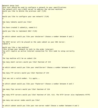
5.1. User Input
Figure 2.A screen capture of the program user interface, with various options completed
There is room for improvement in the user interface as this program uses a CLI. While the program works without issue, the interface used is not as easy to use as a Graphical User Interface (GUI), which would offer a better display of the various options available to the user. The method used to garner the users subnet choice is also an area that could be improved.
6. Discussion
Research was conducted into common network services and cyber defence exercises in the literature review. A networked system was planned and created (see3), this network can also be configured to a users specifications (see5) which gives multiple learning opportunities in the practical implementation of networks and programming. The creation of the network puts into practice the services researched in the literature review.
present different vulnerabilities or may react differently to different attack types. More research would have to be conducted in this area to gain a better understanding of how different daemons operate.
Currently, it is possible to use the program to create more nodes on a given subnet than is possible to address, the maximum being two-hundred and fifty-five. Doing so would likely create problems within the network. The improvement would involve a calculation to check how many nodes are already assigned to a subnet and then give an error message if a user attempts to add more than two-hundred and fifty-five. Improving the way the DNS and DHCP servers function would also be desirable. Currently the DNS and DHCP servers have to be on the same subnet; if they are not, the DNS server will not function correctly. It would be useful if this was not the case as it would allow more user configuration. Implementing this would require changes to the program to make this option configurable, it would likely also require a reconfiguration of the two servers to allow them to communicate from separate subnets. More research would be required to make this improvement as it may not be possible to implement this. Finally extensive tests have been implemented. These tests are used to test that the functions work as described.
Author Contributions: Samuel Chapman and Helge Janicke conducted requirement specification; Samuel Chapman implemented the virtual network; Samuel Chapman and Richard Smith generated and captured network traffic; Samuel Chapman and Leandros Maglaras performed system testing
Conflicts of Interest:The authors declare no conflict of interest
Appendix A. Technical Network Report
A general overview of the network configuration and daemons used has been provided. This appendix aims to provide a more detailed explanation of the network and how it was setup. A network created in Netkit-NG is made up of several different files and folders.lab.conf andlab.depfiles are used by Netkit-NG for lab configuration detail. Netkit-NG requires each node to have a folder and a.startup file with the node’s name, both of which can be empty, however, in most cases in this network are not. The node folders contain files and folders the user would like in the specific node, for example if the filetest.txtwas required forpc1this would be placed in its folder. The.startupfile contains a bash script the user would like to run when a particular node is started, for example if the user required thels command run whenpc1was started this command would appear inpc1.startup.
Appendix A.1. Lab.conf
Thelab.conf file contains details regarding the hardware configuration for individual network nodes. It is possible to configure the amount of memory each node has as well as how many network interfaces they have and on which collision domain these interfaces sit. It was not deemed necessary to configure the amount of memory each node has as Netkit-NG nodes do not require a significant amount for the purpose intended, however if required for systems with scarce resources this can be set. The network interfaces are configured as such:
Listing 1: Example of the contents of the lab.conf file
r o u t e r 0 [ 0 ] =A r o u t e r 0 [ 1 ] =D
Appendix A.2. Lab.dep
Similar to the lab.conf file lab.dep provides configuration information for the network, however, this file is used to allow parallel start-up of Netkit-NG nodes, and to define an order regarding when each node should start-up. Simply providing a lab.dep file in the lab directory is enough to enable parallel start-up, which allows several nodes to start-up at once. The start-up order of nodes is defined using the following syntax:
Listing 2: Example of the contents of the lab.dep file
h t t p S e r v e r : dhcpServer dnsServer
The node before the colon is the node the rule is intended for. After the colon are the nodes you would like started before the one in question. Simply put the rule states that httpServer will not start-up until dhcpServer and dnsServer have started. In the created network, all nodes must wait until the DHCP server has started and most must wait until at least one router and the DNS server has started. The DHCP server is started first to ensure all other nodes are able to retrieve IP addresses from it. The routers should be started before other nodes to ensure all are able to contact the DHCP server for these addresses. Because the network uses DDNS the DNS server is required to start-up before other nodes so that the DHCP server is able to update its records.
Appendix A.3. Collision Domain: TAP
The TAP collision domain contains the TAP node on the network. This node acts as a gateway to the internet however does not differ greatly from the router nodes on the network (seesubsection A.4), it uses commands placed in the tap.startup file to add routes to the other collision domains:
Listing 3: Commands used by the TAP nodes to add routes to other collision domains file r o u t e add −n e t 1 9 2 . 1 6 8 . 0 . 0 netmask 2 5 5 . 2 5 5 . 2 5 5 . 0 gw 1 9 2 . 1 6 8 . 4 . 1 0 e t h 1 r o u t e add −n e t 1 9 2 . 1 6 8 . 1 . 0 netmask 2 5 5 . 2 5 5 . 2 5 5 . 0 gw 1 9 2 . 1 6 8 . 4 . 2 0 e t h 1 r o u t e add −n e t 1 9 2 . 1 6 8 . 2 . 0 netmask 2 5 5 . 2 5 5 . 2 5 5 . 0 gw 1 9 2 . 1 6 8 . 4 . 3 0 e t h 1
The first route command tells the node that any traffic with an IP address in the range 192.168.0.0 - 192.168.0.255 should be sent to the address 192.168.4.10. The other commands work in a similar manner. The lab.conf file for the TAP node is not like other nodes. The rule for the TAP machine is:
Listing 4: Commands used in the lab.conf file specific to the setup of the TAP node.
tap [ 0 ] = tap , 1 9 2 . 1 6 8 . 4 4 . 1 3 0 , 1 9 2 . 1 6 8 . 4 4 . 1 5 0 tap [ 1 ] =D
Like a router this node has a network interface that sits on collision domain D. However, it has a second interface that sits on the TAP collision domain, the name tap is special in Netkit and allows the machine to communicate to the internet. Of the two IP addresses, the first is that of the host machine, and the second IP is the IP you would like to give to the tap nodes interface zero.
The tap node uses a slightly different resolv.conf file to the other machines. The resolv.conf file contains a list of DNS servers a node is able to contact, the tap node’s resolv.conf looks like:
Listing 5: The resolv.conf file used in the TAP node.
nameserver 1 9 2 . 1 6 8 . 0 . 5 nameserver 8 . 8 . 8 . 8
When the tap node starts it also installs the text-based web browser, Links. This is achieved using the command:
Listing 6: Installation used in tap.startup
apt−g e t i n s t a l l l i n k s
The tap machine connects to the internet and therefore does not require anything more to install this program.
Appendix A.4. Collision Domain: D
As stated insubsection A.3this collision domain contains the routers for the network. The routers of this network are setup in the same way, the only differences being that the IP addresses differ between routers, as such only router0 will be explained in detail. The lab.conf file assigns two interfaces to the router, 1 and 2 (seeListing 1), and the lab.dep file ensures the router cannot start until dhcpServer has started. router0.startup contains a number of commands for different purposes. The first command segment sets the IP addresses for both interfaces:
Listing 7: Command used in router0.startup to configure its IP address
i f c o n f i g e t h 0 1 9 2 . 1 6 8 . 0 . 5 5 up i f c o n f i g e t h 1 1 9 2 . 1 6 8 . 4 . 1 0 up
The IP address for the router was assigned statically to ensure it cannot be changed by the DHCP server, and the router always has the same IP. The next command segment assigns the router its routes:
Listing 8: Command used in router0.startup to configure its routing
r o u t e add −n e t 1 9 2 . 1 6 8 . 2 . 0 netmask 2 5 5 . 2 5 5 . 2 5 5 . 0 gw 1 9 2 . 1 6 8 . 4 . 3 0 e t h 1 r o u t e add −n e t 1 9 2 . 1 6 8 . 1 . 0 netmask 2 5 5 . 2 5 5 . 2 5 5 . 0 gw 1 9 2 . 1 6 8 . 4 . 2 0 e t h 1 r o u t e add d e f a u l t gw 1 9 2 . 1 6 8 . 4 . 4 0
These routes are assigned in the same way as the tap node, however a default route has been added. This was added so that any traffic intended for an IP not listed would go through the tap node and thus the internet. The final command segment consists of the setup and installation of ISC-DHCP-Relay (seesubsection 3.2). The command segment is as follows:
Listing 9: Command used in router0.startup to configure and install the DHCP relay used
echo " i s c−dhcp−r e l a y i s c−dhcp−r e l a y / s e r v e r s s t r i n g dhcpServer . t e s t . s c . com" | debconf−s e t−s e l e c t i o n s echo " i s c−dhcp−r e l a y i s c−dhcp−r e l a y / i n t e r f a c e s s t r i n g " | debconf−s e t−s e l e c t i o n s
echo " i s c−dhcp−r e l a y i s c−dhcp−r e l a y / o p t i o n s s t r i n g " | debconf−s e t−s e l e c t i o n s
apt−g e t update
apt−g e t −−f o r c e−yes i n s t a l l i s c−dhcp−r e l a y −y
The first three echo statements contain setup information for the DHCP relay. This information is stored by the node and used to set options when ISC-DHCP-Relay is installed. The first command sets the DHCP server location to dhcpServer.test.sc.com, this is where DHCP requests will be forwarded when received by the router. The second leaves the interface field blank, leaving it blank allows the relay to detect which interface should forward DHCP requests. The final command is blank, to stop ISC-DHCP-Relay asking for additional options. These options are set to ensure the scripted installation requires no additional user setup. The apt-get update command is used to update where apt-get will look when installing new packages, this is used because the relevant files are installed from files local to the node. The installation uses local files so an internet connection isn’t required for the lab to function (seesubsubsection A.4.1).
Listing 10: resolv.conf file used for router0
domain t e s t . s c . com nameserver 1 9 2 . 1 6 8 . 0 . 5
The first line tells the node what the local domain is, this means that when the node attempts to communicate with another node on the network it does not have to use the fully qualified domain name (i.e. remote1.test.sc.com), it can instead use just the hostname of that node (i.e. remote1). The next line points the node to the local DNS server.
Appendix A.4.1. Installing from Local Files
Installing a program using local files requires several steps. The required files were downloaded, in the .deb format on a host machine, this included any dependencies. These files were then placed in the etc/debPackages folder on the node that required them. Once the files were downloaded the following command was run on the host machine.
Listing 11: Command used to create a zip file from the packages.
dpkg−scanpackages . /dev/ n u l l | gzip −c9 > Packages . gz
This command creates a zip file with information regarding the .deb files.
The host’s etc/apt/sources.list file was then changed so that it contained the single line: Listing 12: Altered contents of the /etc/apt/sources.list file.
deb f i l e :/// e t c /debPackages /
This line tells the node to look in the /etc/debPackages folder for packages. When the apt-get install command is run on the node it will now install without using an internet connection. This process has been repeated throughout the network as it is a fast and simple method of installing required applications, without an active connection to the internet.
Appendix A.5. Collision Domains: B & C
These subdomains do not contain any server daemons (seesubsection 3.3) and therefore require minimal setup, these are referred to as remote nodes. Each node has only one interface that sits on either collision domain B or C, the lab.dep file contains a variation of the line:
Listing 13: lab.dep file showing the start-up order for the remote nodes
remote1 : dhcpServer dnsServer r o u t e r 0 r o u t e r 1
The name of each node will change as will the name of the last router, depending on the machine and collision domain it will be placed on.
The node’s .startup files are very similar, each contain the command:
Listing 14: Command used to query a DHCP server for an IP address d h c l i e n t e t h 0
This command makes the node query for a DHCP server when it starts up. If a DHCP server is found it will send and request several pieces of information for its eth0 interface, if one is not found the device will not obtain any information and the interface will not be able to communicate with the network which is why it is important that these devices start after both the dhcpServer and the routers.
The information sent and requested by the dhclient command is defined in etc/dhcp/dhclient.conf. The information sent is done so via the below segment:
Listing 15: Command used to send a node’s hostname to the DHCP server, for DDNS purposes.
This will send the host name of the node to the DHCP server, which is used for DDNS (see subsubsection A.6.6). The next segment in dhclient.conf is:
Listing 16: Information requested from the DHCP server using dhclient.
r e q u e s t subnet−mask , b r o a d c a s t−address , time−o f f s e t , r o u t e r s , domain−name , domain−name−s e r v e r s , domain−search , host−name , dhcp6 . name−s e r v e r s , dhcp6 . domain−search ,
n e t b i o s−name−s e r v e r s , n e t b i o s−scope , i n t e r f a c e−mtu , ntp−s e r v e r s ;
This will request various information from the DHCP server that will allow/aid the node in communicating with the network.
A default route is added on start-up (seeListing 8), however these nodes will use the IP address of 192.168.1.11 or 192.168.2.22, this is collision domain dependant. The final section in the .startup files is the installation of the Links web browser, this is installed offline (seesubsubsection A.4.1).
The Pine program is installed on these nodes as an email client (seesubsection 3.3). This requires several files to work, one of which is the root/mail/sent-mail file, this contains information used by Pine for its mail folder and is used for no other purpose. The Pine program is held in usr/local/bin/pine , and the Pine manual page is held in usr/share/man/man1/pine.1. It also requires the hidden file root/mail/.pinerc, this file contains a large amount of configuration information for the Pine application. Pine requires a line to be added in this file. This line is shown below and is added at line 29.
Listing 17: .pinerc line 29. Used to locate the user’s email inbox. inbox−path ={ imap . t e s t . s c . com/u se r=remote1 } inbox
This line makes Pine look for the inbox of remote1 on the IMAP server in the /usr directory. The final section in the remote nodes .startup file is the following lines:
Listing 18: Command to start a bash script. This bash script is used to automatically replay network traffic.
bash /hosthome/Documents/ n e t k i t L a b s / r e p l a y S c r i p t s / m a s t e r R e p l a y S c r i p t . sh & disown
The first line will start the bash script located at the specified file path, which will then run in the background. This script is used to replay network traffic (seesection 4). The second line is used because the nodes would hang during the start-up procedure, and this was found to stop this.
Like the routers (seesubsection A.4) the nodes in this collision domain use the resolv.conf file. The configuration adds a third line. This line is a second nameserver and is used to allow the node to query a non-local DNS server, which is capable of resolving internet requests.
Appendix A.6. Collision Domain: A
Listing 19: Command to start the SSH daemon, used for remote login to server nodes.
/ e t c / i n i t . d/ssh s t a r t
Once started a user is added, to allow access to the node via SSH. A user is added using the command:
Listing 20: Command to start a bash script add a new user to a network node.
useradd −d /home/ t o o r −m−s /bin/bash t o o r echo ’ t o o r : root ’ | chpasswd
This adds a user called root and the appropriate directories. The user is then given the password toor. While not being a very secure password this is done for the purpose of this network scenario as password cracking will not be a focus of this environment.
Like the routers (seesubsection A.4), the server nodes in this collision domain use the resolv.conf file. The configuration used is the same as used by the router nodes.
Appendix A.6.1. FTP Server
All configuration for ftpServer is contained in its .startup file. Firstly, it will query the DHCP server for an IP address (seesubsubsection A.6.5). ftpServer will then add users (remote0-remote8) (seeListing 20), this is a simple operation but it is required to establish a connection with the proftpd daemon. Once the users have been added the FTP daemon is started:
Listing 21: Command used to start the ProFTPd daemon, used for the FTP and SFTP servers. / e t c / i n i t . d/proftpd s t a r t
Appendix A.6.2. SFTP Server
The sftpServer.startup file is exactly the same as ftpServer.startup, however sftpServer contains the file /etc/proftpd/conf.d/sftp.conf. This file instructs the proftpd daemon to use the SFTP protocol rather than standard FTP. It also states which port to use and that it should use a public key. This is the only difference between the two server nodes.
Appendix A.6.3. HTTP Server
In addition to the commands discussed insubsection A.6 httpServer.startup contains the following lines:
Listing 22: Command used to allow the use of HTTPS webpages, and the command to start the apache2 HTTP/HTTPS server.
# e n a b l e s s l s i t e a 2 e n s i t e d e f a u l t−s s l a2enmod s s l
# S t a r t apache s e r v e r / e t c / i n i t . d/apache2 s t a r t
The first two lines enable the apache2 SSL modules. These modules allow apache2 to use HTTPS as well as standard HTTP. The last line starts the apache server daemon.
Man_page_of_VSTART.html, these pages simply provide proof that httpServer works and can be accessed via the Links program using the address
http://httpServer.test.sc.com/ and then the name of the file.
Implementing HTTPS requires more configuration. In order for SSL to work a certificate must be generated, this certificate is used to confirm the identity of the server to the client node, for the purposes of this network it was decided to sign this certificate myself to ensure the network does not directly require an internet connection to function. To self-sign a certificate a tutorial was followed provided by Zahn and Zahn (n.d.), this goes through the entire process. Once the correct files were generated a small number of changes were made. These changes took place in the httpServer/etc/apache2/sites-available file. The document root, on line five, was changed from /var/www to /var/ssl as was the directory, on line ten. These two changes ensure that httpServer is capable of using both the HTTP and HTTPS protocols.
Another change made to the same file was the addition of the following lines:
Listing 23: The commands used to ensure the apache2 server uses the right directory for the self-signed SSL certificate and key.
S S L C e r t i f i c a t e F i l e / e t c /apache2/ s s l / h t t p s . c r t S S L C e r t i f i c a t e K e y F i l e / e t c /apache2/ s s l / h t t p s . key
These lines enforce the directory where apache will look for the .crt and .key files, the names of these files were also changed, these changes helped to make the files easier to locate if further changes were required.
As with the standard HTTP webpages a very basic page was created in the httpSever/var/ssl directory. When httpServer is started the page that implements HTTPS can be reached using the address
https://httpServer.test.sc.com/ssl.html. Appendix A.6.4. Email Server
The emailServer.startup file is similar to the other nodes on this collision domain, however like the FTP server it adds several users (seeListing 20). The email server also includes some installs that have been scripted (seesubsubsection A.4.1). The commands used to script the installation are:
Listing 24: Commands used to script the installation and configuration of the exim4 email server daemon.
apt−g e t update
apt−g e t −−f o r c e−yes i n s t a l l exim4 −y chmod 644 / e t c /exim4/exim4 . conf
chown r o o t : r o o t / e t c /exim4/exim4 . conf / e t c / i n i t . d/exim4 s t a r t
/ e t c / i n i t . d/openbsd−i n e t d s t a r t
In addition to the installation commands are the chmod and chown commands. These are used to change the permissions of the exim4.conf file, the permissions had to be changed as there were errors encountered when starting exim4 initially which were diagnosed as permission related. Similar to the nodes in collision domains B and C this node contains the Pine application as well as the imapd and pop3d daemons(seesubsection 3.4).
contains information about the network so exim4 can function properly and only receive traffic from a certain range of IP addresses.
Like the standard nodes (seesubsection A.5) the email server uses Pine. It is used here to allow emails to be stored in a remote inbox. The only change required in the hidden file .pinerc is following line eighty where the following is added:
Listing 25: Line of the .pinrc file that allows the Reply-to field to be automatically filled in when using the Pine email client.
customized−hdrs=Reply−To : remo te1@t est . s c . com
This allows the Reply-To field to be automatically filled in, while not strictly necessary this makes it easier for the nodes to communicate via email.
Appendix A.6.5. DHCP Server
dhcpServer uses most of the commands used by the other server nodes (seesubsection A.4), however it does not use dhclient, instead it uses the following:
Listing 26: Commands used to give the DHCP server a hardware and IP address.
i f c o n f i g e t h 0 hw e t h e r 0 0 : 0 0 : 0 0 : 0 0 : 0 0 : 0 3 up i f c o n f i g e t h 0 1 9 2 . 1 6 8 . 0 . 7 up
These commands set a hardware address for eth0, and subsequently assign an IP address for eth0. A hardware address is assigned to ensure the DHCP server will not attempt to give its assigned address to another node. This is done by defining a static lease in the dhcpd.conf file (seeListing 32).
After eth0 has been configured the following commands are run:
Listing 27: Commands used to install, configure and start the DHCP server daemon. apt−g e t update
apt−g e t −−f o r c e−yes i n s t a l l i s c−dhcp−s e r v e r −y
cp / e t c /dhcp/myConf/dhcpd . conf / e t c /dhcp
s e r v i c e i s c−dhcp−s e r v e r r e s t a r t
This installs the server daemon (seesubsection 3.4), a configuration file is then copied and the server daemon is restarted. The configuration file is copied as there is a dhcpd.conf file already in the dhcpServer/etc/dhcp directory. Under normal circumstances this would be replaced on start-up if the file was present in the lab directory structure, however when ISC-DHCP-Server is installed this file is replaced, because of this the file has to be copied into the directory following installation of the server daemon. After copying the new configuration file the server daemon has to be restarted to ensure the daemon uses the new file. Following this is the installation and configuration of the ISC-DHCP-Relay daemon, this is the same as the routers (seeListing 9).
ISC-DHCP-Server uses two files for its configuration, dhcpServer/etc/default/isc-dhcp-server and dhcpServer/etc/dhcp/myconf/dhcpd.conf. The first file is used, in this lab, to configure what interface the DHCP server should serve requests from, the following line was used:
Listing 28: Line in the dhcpd.conf file. This specifies the network interface the DHCP server should serve IP addresses from.
INTERFACES=" e t h 0 "
Thedhcpd.conffile is used to specify how the DHCP server allocates addresses and communicates with the network, and in this case how it updates the DNS server with the addresses it distributes. It should be noted that this file is divided into sections, which are denoted by curly braces and a semi colon . In order to update the DNS server the following lines are used:
Listing 29: Lines within the dhcpd.conf file used to update the DNS server with network information. ddns−update−s t y l e i n t e r i m ;
update−s t a t i c−l e a s e s on ;
key ddns . key {
a l g o r i t h m hmac−md5 ;
s e c r e t NvoL1uVTOeWOmWQPbip1Rg==; } ;
zone t e s t . s c . com { primary 1 9 2 . 1 6 8 . 0 . 5 ; key ddns . key ;
}
zone r e v e r s e . in−addr . arpa { primary 1 9 2 . 1 6 8 . 0 . 5 ; key ddns . key ;
}
o p t i o n domain−name " t e s t . s c . com " ;
o p t i o n domain−name−s e r v e r s dnsServer . t e s t . s c . com ;
The first line enables the DHCP server to send updates to the DNS server, and the second ensures that it will send updates about any static IP addresses that are assigned later in the file. The next section, starting key ddns.key, defines a key that should be sent by the DHCP server daemon when it updates the DNS server, this is used as a method of authentication so the DNS server does not accept updates unless the key is provided. The two sections that begin zone denote the two DNS zones that dhcpServer can update (seesubsubsection A.6.6), you will also notice that the aforementioned key is referred to in these sections, this is provided when the DHCP server updates the zone. The final lines inform the DHCP server of the domain name and the location of the DNS server it will be updating.
The next four lines in dhcpd.conf are as follows:
Listing 30: Lines of the dhcpd.conf file used to set server settings.
d e f a u l t−l e a s e−time 6 0 0 ; max−l e a s e−time 7 2 0 0 ;
a u t h o r i t a t i v e ;
log−f a c i l i t y l o c a l 7 ;
Following the aforementioned sections are three sections that define subnets and the addresses the DHCP server can assign within those subnets. The sections are of a similar structure and look like:
Listing 31: Lines of the dhcpd.conf file used to create a subnet.
subnet 1 9 2 . 1 6 8 . 1 . 0 netmask 2 5 5 . 2 5 5 . 2 5 5 . 0 { range 1 9 2 . 1 6 8 . 1 . 5 0 1 9 2 . 1 6 8 . 1 . 2 5 0 ;
d e f a u l t−l e a s e−time 6 0 0 ; max−l e a s e−time 7 2 0 0 ;
o p t i o n r o u t e r s 1 9 2 . 1 6 8 . 1 . 1 1 ; o p t i o n ip−forwarding o f f ;
o p t i o n domain−name−s e r v e r s 1 9 2 . 1 6 8 . 0 . 5 ; o p t i o n b r o a d c a s t−address 1 9 2 . 1 6 8 . 1 . 2 5 5 ; o p t i o n subnet−mask 2 5 5 . 2 5 5 . 2 5 5 . 0 ;
}
The first line defines the subnet as 192.168.1.0 with a netmask of 255.255.255.0. The netmask is the range of IP addresses available to the subnet in this case the available addresses are in the range 192.168.1.0 - 192.168.1.255. The next line sets the range of IP addresses the DHCP server is actually able to assign. The two lines following this reiterate the lease times assigned earlier. The fifth line simply states the IP address of the router for a particular subnet. Following that line is one that turns off ip-forwarding, this is normally turned on if there is a router being assigned an address. The final three lines are information regarding the network, and is sent to the client node.
The final section in dhcpd.conf defines any client nodes which should have fixed IP addresses: Listing 32: Lines of the dhcpd.conf file used to set static IP addresses.
h o s t dnsServer {
hardware e t h e r n e t 0 0 : 0 0 : 0 0 : 0 0 : 0 0 : 0 1 ; f i x e d−address 1 9 2 . 1 6 8 . 0 . 5 ;
}
The first line simply denotes the node the rule applies to, this name does not have to be the name of the node, however, doing so makes the rule easier to read/understand. The second line is the hardware address of the node the rule applies to, this information is supplied by each node when they query the DHCP server. The final line is the IP address that will be given to the specified device. Fixed addresses are used for the DHCP and DNS server nodes, because if they were to change address the network would not function properly.
Appendix A.6.6. DNS Server
Like the other server nodes on this collision domain this node use the same .startup file, with the addition of the following line:
Listing 33: Command used to start the DNS server daemon, Bind9.
/ e t c / i n i t . d/bind9 s t a r t
is compared against. The rest of the file contains information about the various zones under the control of this DNS server, there are two zones in this particular configuration file. The first zone is defined as:
Listing 34: Lines from the named.conf.local file used to allow updates from a server with the correct key.
zone " t e s t . s c . com" { type master ;
f i l e "/ e t c /bind/db . com . s c . t e s t " ; allow−update { key ddns . key ; } ;
} ;
The first section defines a new zone, test.sc.com, and states that this DNS server is the master of that zone, this means that it is the authoritative name server for the particular zone. Following this is a line with the location of a file, this file will be explained in more detail in the following paragraph. The final line states that the server should allow updates to this zone if the key in ddns.key is provided. The second zone is very similar to this one however it is called reverse.in-addr.arpa and the related file is located at /etc/bind/zones/reverse.db.com.sc.test , the contents of which will be explained in a subsequent paragraph. This zone is used for reverse lookups, these are like normal DNS lookups (i.e using domain names to find IP addresses) except the opposite way around.
The file dnsServer/etc/bind/db.com.sc.test contains information about the test.sc.com zone. The first section of this files relates to refresh rates of the DNS records, and when they expire. The next section is where records are denoted, records are used by the DNS server to locate a node based on its domain name. Typically, a record looks like:
Listing 35: DNS record for the DHCP server.
dhcpServer . t e s t . s c . com . IN A 1 9 2 . 1 6 8 . 0 . 7
This denotes that the domain name dhcpServer.test.sc.com. refers to the node with the IP address at the end of the line. There are few records in this file given that most of the network’s nodes are given records using Dynamic DNS. Some exceptions exist and this is mostly for email protocol as emails are not addressed to a specific node’s host name, the lines used for email are shown below.
Listing 36: DNS records for domains used by the email server.
mail . t e s t . s c . com . IN A 1 9 2 . 1 6 8 . 0 . 8 imap . t e s t . s c . com . IN A 1 9 2 . 1 6 8 . 0 . 8 pop . t e s t . s c . com . IN A 1 9 2 . 1 6 8 . 0 . 8
These all relate to the location of the email server.
The second file used by Bind9 was /etc/bind/zones/reverse.db.com.sc.test. The contents of which look very similar to that described above, however the lines denoting domain names are in reverse:
Listing 37: Reverse DNS records.
7 . 0 . 1 6 8 . 1 9 2 IN PTR dhcpServer . t e s t . s c . com .
This allows the DNS server to resolve queries that look for the domain name of a given IP address.
References
1. Cook, A.; Smith, R.; Maglaras, L.; Janicke, H. Measuring the risk of cyber attack in industrial control systems. BCS eWiC, 2016.
3. Mullins, B.E.; Lacey, T.H.; Mills, R.F.; Trechter, J.E.; Bass, S.D. How the cyber defense exercise shaped an information-assurance curriculum. IEEE Security & Privacy2007,5.
4. Adams, W.J.; Gavas, E.; Lacey, T.H.; Leblanc, S.P. Collective Views of the NSA/CSS Cyber Defense Exercise on Curricula and Learning Objectives. CSET, 2009.
5. Johnson, C.; Badger, L.; Waltermire, D.; Snyder, J.; Skorupka, C. Guide to cyber threat information sharing. NIST Special Publication2016,800, 150.
6. Cruz, B.; Gupta, D.; Kapoor, A.; Haifei, L.; McLean, D.; Moreno, F.; others. McAfee Labs threats report. McAfee Inc., Santa Clara, CA. Available: http://www. mcafee. com/us/resources/reports/rp-quarterlythreat-q1-2014. pdf2014.
7. Hansman, S.; Hunt, R. A taxonomy of network and computer attacks. Computers & Security2005,24, 31–43. 8. Chapman, I.M.; Leblanc, S.P.; Partington, A. Taxonomy of cyber attacks and simulation of their effects. Proceedings of the 2011 Military Modeling & Simulation Symposium. Society for Computer Simulation International, 2011, pp. 73–80.
9. Janbeglou, M.; Zamani, M.; Ibrahim, S. Redirecting network traffic toward a fake DNS server on a LAN. Computer Science and Information Technology (ICCSIT), 2010 3rd IEEE International Conference on. IEEE, 2010, Vol. 2, pp. 429–433.
10. Fuertes, W.M.; de Vergara, J.E.L. A quantitative comparison of virtual network environments based on performance measurements. Proceedings of the 14th HP Software University Association Workshop, Garching, Munich, Germany, 2007, pp. 8–11.
11. Wolny, W.; Szołtysik, M. Overview of Existing Computer Network Environments Virtualization for Computer Network Learning. Studia Ekonomiczne2014,188, 250–264.
12. Pizzonia, M.; Rimondini, M. Netkit: easy emulation of complex networks on inexpensive hardware. Proceedings of the 4th International Conference on Testbeds and research infrastructures for the development of networks & communities. ICST (Institute for Computer Sciences, Social-Informatics and Telecommunications Engineering), 2008, p. 7.
13. Ruiz-Martinez, A.; Pereniguez-Garcia, F.; Marin-Lopez, R.; Ruiz-Martínez, P.M.; Skarmeta-Gomez, A.F. Teaching advanced concepts in computer networks: Vnuml-um virtualization tool. IEEE Transactions on Learning Technologies2013,6, 85–96.
14. Márquez, F.G.; Cambronero, D.F. Distributed Virtualization Scenarios Using VNUML. 1st International DMTF Academic Alliance Workshop on Systems and Virtualization Management: Standards and New Technologies, Vol. 2007.
15. Li, P. Selecting and using virtualization solutions: our experiences with VMware and VirtualBox. Journal of Computing Sciences in Colleges2010,25, 11–17.
16. Hillestad, O.I.; Libak, B.; Perkis, A. Performance evaluation of multimedia services over ip networks. Multimedia and Expo, 2005. ICME 2005. IEEE International Conference on. IEEE, 2005, pp. 1464–1467. 17. Duck, M.; Read, R.Data communications and computer networks: for computer scientists and engineers; Pearson
Education, 2003.
18. Dean, T.Network+ guide to networks; Cengage Learning, 2012.