ISSN (Online): 2320-9364, ISSN (Print): 2320-9356
www.ijres.org Volume 4 Issue 12 ǁ December. 2016 ǁ PP.01-09
The Research of PID algorithm On Attitude controller for
Four-rotor UAV
ZexiangZhang
(Shanghai University of Engineering Science, Department of Air Transportation, Shanghai 201620)
Abstract: In order to solve the flight control problem of Four-rotor UAV. The transfer function of the pitch, roll and yaw passages is established by the coordinate transformation and the attitude calculation of the four-rotor
UAV. The PID controller is used to control the flight attitude of the four-rotor unmanned aerial vehicle.
MATLAB / Simulink simulation results show that: PID controller can effectively achieve the quad-rotor UAV
control, significantly reduced thesteady-state error of UAS such that the stability of the entire UAV system has
been improved. It has certain reference value and guidance significance to the research of UAV system stability
in the future.
Key words: Four-rotor UAV; Attitude control; PID controller; MATLAB / Simulink simulation
I.
INTRODUCTION
With the continuous development of space technology, quad-rotor UAV with its unique shape and
lightweight structure, simple and can be fixed VTOL hover, and operation of flexible control, etc., are concerned
by more and more scholars and researchers[1].
Four-rotor unmanned aerial vehicle is different from the helicopter. It changes the flight attitude by
changing the speed of the motor mounted at the four end points of the fuselage without the need for a tail[2]. So
the power of quad-rotor UAV stronger, more stable flight attitude.
In recent years, the application of four-rotor unmanned aerial vehicles more and more widely. So ensuring the
quality of flight has become a hot research. The key factor to determine the quality of the flight is the control
effect of the four-rotor flight attitude.
At present, the attitude modeling of four-rotor unmanned aerial vehicle (UAV) is basically belong to
the category of nonlinear control[3]. Non-linear control requires a high-precision control model. So under the
premise of a certain error, using PID control algorithm to control the effect is more obvious. In this paper, a PID
controller is designed for this characteristic, which makes the performance of the system more good.
II.
NONLINEAR MATHEMATICAL MODEL OF FOUR ROTOR
Quad-rotor UAV having the structure X-type, Which is a non-linear input 4 and 6 degrees of freedom,
multi-variable, typically due to high coupling drive system[4,5]. In order to make the dynamic model of four-rotor
unmanned aerial vehicle (UAV) not general, the paper puts forward some reasonable hypotheses:
① the quad-rotor UAV as rigid, symmetrical structure and quality.So the inertial matrix can be defined as a diagonal matrix
I
.② Four-rotor UAV center of gravity, center of mass and geometric center is consistent with the origin UAVs
built for double coordinate system.
③ Ignore the impact of quad-rotor UAV suffered surface air resistance and other factors.
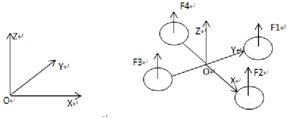
Quad-rotor UAV structural model[6] shown in Figure 1-1:
Figure 1-1 Quad-rotor UAV structural model
In order to facilitate the establishment of quad-rotor UAV model, we need to establish two coordinate
systems, Inertial coordinate system E (OXYZ) and quad-rotor UAV body coordinate system B (oxyz). The
inertial coordinate system E is characterized by Euler angle. Euler angles are used to determine a set of
independent variables fixed rigid body rotating position. Here,
represents the pitch angle ,
represents the roll angle,
represents the yaw angle.According to the angular momentum theorem, the momentum moment of the moment to the rigid body is equal to the change of the rigid body angular momentum.Figure 1-2 inertial coordinate system
According to Newton's second law,
F
m
dv
dt
,
F
is a quad-rotor UAV by the sum of external forces.m
is thequality of the four-rotor unmanned aerial vehicle.
v
is the speed of four-rotor unmanned aerial vehicle. F isdecomposed into four rotary wing unmanned aerial vehicle body coordinate system, three components can be
obtained. Respectively
F
x、F
y、F
z.The corresponding angular velocity
decomposition to the four-rotorUAV body coordinate system can get three components.Respectively,
p
、q
、r
. According to the four-rotor UAV dynamic equation[7],M
dH
dt
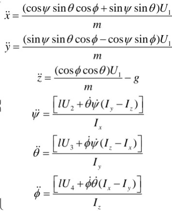
In summary, according to the four-rotor unmanned aerial vehicle of the force analysis, Newton's second law, and
four-rotor UAV dynamic equation. We can get the four-rotor unmanned aerial vehicle linear motion equation:
4 2 1 1 1 4 2 2 2 1 4 2 3 3 1
(cos
sin cos
sin
sin )
(sin
sin cos
cos
sin )
(cos cos )
t x i t y i t z i
k
K x
i
F
K x
x
m
m
k
K y
i
F
K y
y
m
m
k
K z
i
F
K z
mg
z
g
m
m
(1-1)According to the calculation and analysis of moment of momentum,
M
can be decomposed into the quad-rotor UAV airframe coordinates. Respectively,M
x、M
y、M
z.
In summary, combined with Conversion Model Euler angles and the angular velocity between the quad-rotor
UAV and the Inertial diagonal matrix
I
.We can get four-rotor unmanned aerial vehicle angular motion equation:(
)
(
)
(
)
x x z
x
y z x
y
z x y
z
M
I
I qr
I
p
M
I
I rp
q
I
r
M
I
I
pq
I
(1-2)There are four groups of four-rotor UAV control channel and these four groups of channels are independent of
each other. Assuming control inputs are
U
1、U
2、U
3、U
4.According to a four-rotor UAV attitude kind of change, we can obtain the following relationship:
4 2
1 2 3 4
1
1
4 2 2 2
2
4 2
3 1 2 2
3
3 1
2 4 1 3 2 2 2 2
4
1 2 3 4
(
)
(
)
(
)
t i i t t dk
F
F
F
F
U
F
F
U
k
F
F
U
k
F
F
F
F
U
k
(1-3) 1U
produces a vertical movement effect, which is the amount of vertical control,U
2creates a rollover effect forIn summary, combined with the linear motion equation and angular motion equation of the four - rotor
unmanned aerial vehicle (UAV), a simplified mathematical model can be obtained under the condition of
neglecting the resistance and the change of the surface factors:
1 1 1 2 3 4
(cos
sin cos
sin
sin )
(sin
sin cos
cos
sin )
(cos cos )
(
)
(
)
(
)
y z x z x y x y zU
x
m
U
y
m
U
z
g
m
lU
I
I
I
lU
I
I
I
lU
I
I
I
(1-4)In this,
l
represents the distance between the rotor center and the origin of the coordinate system.x
,
y
,z
is a four-rotor displacement in thex
,y
,z
-axis direction of the coordinate system.I
x,I
y,I
zis respectively the moment of inertia of the four rotors aboutx
,y
,z
-axisIn order to simplify the system complexity, it is assumed that there exists a satisfied relationship between the
attitude angle and the angular velocity, as follows:
q
、
p
、
r
.Ignoring small perturbations premise, we can get four-rotor UAV state equation:
mx
Ax
Bu
In this
x
[ , , , , , , , , ]
x y z p q r
T,u
[ ,
u u u u
1 2,
3,
4]
.According to the performance parameters of the experimental prototype and the transfer function
1
( )
(
)
G s
sI
A
B
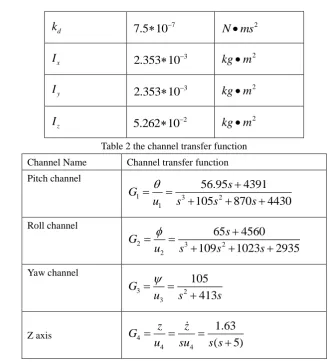
,the transfer function of each channel can be obtained clearly. Table 1 prototype performance parametersparameter name Value unit
l
0.25
m
m
1.25
kg
t
k
5d
k
77.5 10
N ms
2x
I
32.353 10
kg m
2y
I
32.353 10
kg m
2z
I
25.262 10
kg m
2Table 2 the channel transfer function
Channel Name Channel transfer function
Pitch channel
1 3 2
1
56.95
4391
105
870
4430
s
G
u
s
s
s
Roll channel
2 3 2
2
65
4560
109
1023
2935
s
G
u
s
s
s
Yaw channel
3 2
3
105
413
G
u
s
s
Z axis 4
4 4
1.63
(
5)
z
z
G
u
su
s s
III.
PID CONTROLLER DESIGN
In the analog control system, the system consists of a PID controller and the controlled object, analog PID
control system block diagramshown in Figure 2-1:
Figure 2-1 block diagram of analog PID control system
Figure 2-2 PID control system block diagram
∆θ
∆θg ∆δe
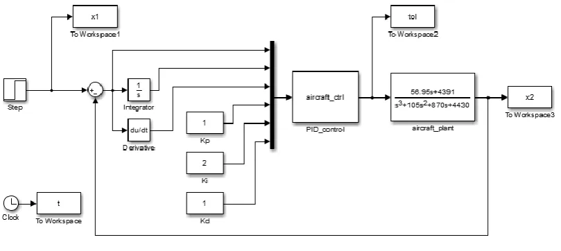
According to the block diagram of PID control system, the simulation system is built on MATLAB / Simulink
simulation platform, and the attitude step response curve of the control system is obtained finally. Control
parameters in Table 3, the corresponding attitude diagram shown in Figure 2, Figure 3, Figure 4.
Table 3 Control parameter settings
Channel Name
p
k
k
ik
dPitch angle 1 2 1
Roll angle 1.5 3.5 0.5
Yaw angle 8 8 0.5
Z-axis direction 8 10 0.8
IV.
PID CONTROL OF MATLAB / SIMULINK SIMULATION
Based on the transfer function of each channel and the simplified model of the four-rotor UAV, a Simulink
simulation model was set up to control each channel independently.
Taking the pitch channel as an example, the controller can be used to obtain the simulation result of other
channel control.
For the pitch channel, the transfer function is: 1
3 2
1
56.95
4391
105
870
4430
s
G
u
s
s
s
Design the output of the PID controller is:
∆δe= Kpe + Ki edt + Kd
de dt
In this ,
e
is the system output error,de
dt
is the reciprocal of the error,edt
is the error integral,K
pis aproportionality coefficient,
K
i is the integration constant,K
dis the differential coefficient. The PID controller output is the motor voltage incrementIn MATLAB Simulink module design of the control system main program structure shown in Figure 3-1.
The simulation results shown:
Figure 3-2 the pitch angle of the unit step response
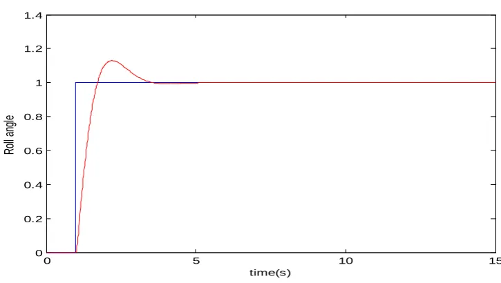
For the roll channel, the transfer function is:
2 3 2
2
65
4560
109
1023
2935
s
G
u
s
s
s
The simulation results shown:
Figure 3-3 the Roll angle of the unit step response
For the yaw channel, the transfer function is:
3 2
3
105
413
G
u
s
s
The simulation results shown:
0 5 10 15
0 0.2 0.4 0.6 0.8 1 1.2 1.4
time(s)
P
itc
h
an
gl
e
0 5 10 15
0 0.2 0.4 0.6 0.8 1 1.2 1.4
time(s)
R
ol
l a
ng
Figure 3-4 the Yaw angle of the unit step response
For the Z-axis direction, the transfer function is: 4
4 4
1.63
(
5)
z
z
G
u
su
s s
The simulation results shown:
Figure 3-5 the Z-axis direction of the unit step response
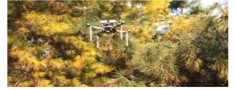
In order to verify the feasibility of the PID controller. We transplanted the PID algorithm to the home-made four
rotor unmanned aerial vehicle for off-field flight(in Figure 3-6), and determine the final control parameters. The
data collected by these sensors is transmitted to the host computer via wife. Test results shown in Figure 3-7
Figure 3-6 the home-made four rotor unmanned aerial vehicle
0 5 10 15
0 0.2 0.4 0.6 0.8 1 1.2 1.4
time(s)
Ya
w
an
gle
0 5 10 15
0 0.5 1 1.5
time(s)
Z
-a
xi
s
di
re
ct
io
Figure 3-7 The data collected by sensors
Among them, the horizontal axis for the second, the vertical axis of the angle, the unity of the order of
magnitude for the 10-1Four-rotor aircraft in the 44 s off the ground, 44 ~ 54 s in the air flight, pitch angle, roll
angle and heading angle of the change is small (within 5 °).
V.
CONCLUSION
The experimental results show that the PID control can adjust the attitude change caused by the
disturbance of the breeze.
MATLAB simulation shows: The four-rotor unmanned aerial vehicle (UAV) system has a higher response speed,
and the PID controller can reduce the steady-state error of the system, which makes the stability of the whole
four-rotor UAV system higher, Interference is stronger, the effect of attitude control is more obvious.
REFERENCES
[1]. KeelongYue, Qingjie Zhang, Huayong Zhu.Research Progress and Key Techniques of Miniature Four -
rotor Unmanned AerialVehicle[J].Electro - Optics and Control,2010,10(10):46-52
[2]. Santos M. Intelligent fuzzy controller of a quadrotor[J]. ISKE.,1990,37(3): 347-353.
[3]. George Limnaios,NikosTsourveloudis.Fuzzy Logic Controller fora Mini Coaxial Indoor Helicopter
[J].J Intell Robot Syst,2012,( 65) : 187 - 201.
[4]. Bowen Nie, etal.Micro four-rotor aircraft Current Status and Key Technology[J]. Electro - Optics and
Control,2007,14(6):113-117
[5]. AlaeddinBaniMilhim.Modeling and Fault Tolerant PID Control of a
Quad-RotorUAV[D].Quebec,Canada: ConcordiaUniversity,2010.
[6]. Bouabdallah S, Murrieri P, Siegwart R. Design and control of anindoor micro quadrotor[C]//IEEE
International Conference onRobotics and Automation. Piscataway, NJ, USA: IEEE, 2004:4393-4398.
[7]. Ly Dat Minh. Modeling and control of quadrotor MAV using visionbasedmeasurement[J]. IEEE Trans.
Circuits Syst., 2010, 33(4): 70-77.
[8]. Oner K T,CetinsoyE,SirimogluE,etal. Mathematical modeling and verti⁃cal flight control of a tilt-wing