Page 51 www.ijiras.com | Email: [email protected]
Over Voltage And Fault Current Limitation In A Distribution
Network With Distributed Generation Units Via Superconducting
Fault Current Limiter
T. Divya M. Sathyapriya
Assistant Professor, The Kavery College of Engineering, Salem, Tamil Nadu
P. Santhoshini
Assistant Professor,
M. Kumarasamy College of Engineering, Karur, Tamil Nadu
I. INTRODUCTION
Almost in every field of recent society there is the requirement of electrical energy which has resulted in a substantial increase of electrical power usage. The introduction of distributed generation causes harmonics and voltage variation in a power system, the introduction of DG is larger, the short circuit current in a distribution system is usual to be increased more, which can bring about the excess of the cut-off capacity of the circuit breaker as well as the difficulty of fault current. For solving these trouble superconducting fault current limiter has been introduced. It is an element, inter-metallic alloy or compound that will carry out electricity without offering resistance below a certain temperature. Under normal operation a fault current limiter insert negligible impedance into the network. When a fault occurs the limiter’s impedance rises rapidly falling the current flowing through it.
In current years, Superconducting fault current limiter has become one of the front position topics of current restrictive technology in the world.
Fault current limiters using high temperature superconductor offer a resolution to controlling the fault current level on utility distribution and transmission networks. In highly interrelated and prolonged power system, faults of enlarged magnitude start creep frequently into the system, so we have to look for a system that can help to decrease these increased magnitudes of fault current. The current restrictive behaviour depends on their non-linear response to temperature, current and magnetic variations. For the application of some type of SFCL into a distribution network with DG units, a few works have been carried out and their research scopes mainly focus on current restriction and security coordination of protective devices. In this paper taking the SFCL as a valuation object its effect on the fault current and overvoltage in a distribution system with various DG units are studied.
Abstract: The introduction of DG into a distribution network may bring lots of compensation, such as emergency backup and peak shaving. Electricity is the driving force behind the industry and next economy. These sources will lead the distribution network to loss its radial nature and increases the fault current level. The SFCL is consists of air-core superconducting transformer and a PWM converter. The SFCL equivalent impedance can be synchronized for restrictive the current and reducing the overvoltage. The SFCL restrictive the fault current and overvoltage, and it can be avoid damage on the significant distribution equipment and improve the system security and reliability. The effects of SFCL studied through theoretical derivation and simulation.
Page 52 www.ijiras.com | Email: [email protected] II. THEORITICAL ANALYSIS
A. INTRODUCTION AND PRINCIPLE OF SFCL
A lot of approaches have been planned to limit the fault current in the earlier period which includes the use of circuit breaker with even more high fault current rating, high impedance transformer and current limiting fuses. Circuit breakers are costly, cannot interrupt fault currents until the first current zero comes and also they have partial lifetime. The high impedance transformers with their high losses make the system ineffective. The fuses have a very low withstand fault current and it has to be replace manually. Fault current is any irregular current that flow through a circuit during the electrical fault situation. For this reason we have introduce the Superconducting Fault Current Limiter. During normal operation, the impedance of SFCL is zero, thus the SFCL conduct without losses. In the event of fault condition, electric current rise above the critical value. Thus the superconductivity of current limiter shut down, resistance of current limiter rises instantaneously, and thus it restrictive the fault current. SFCL is a new power device to automatically limit the fault current to a safe level with the superconducting material goods. A superconductor is a material that can conduct electricity or carry the electrons from one atom to another. Superconductor is used because of sharp transition from zero resistance at usual currents to limited resistance at higher current density.
B. CIRCUIT STRUCTURE OF SFCL
As shown in Fig 1(a), it denote the circuit structure of single phase voltage compensation type SFCL, which consists of air core superconducting transformer and voltage type PWM converter. Ls1, Ls2 are the self inductances of two
superconducting windings. Ms is the mutual inductance. Z1 is
the circuit impedance and Z2 is the load impedance. Ld and Cd
are used for filtering high order harmonics caused by converter. Since the voltage type converter’s capacity of controlling power exchange is implemented by keeping up the voltage of AC side, the converter can be thought as a controlled voltage source Up. By neglecting the losses of
transformer, the SFCL’s equivalent circuit is shown in Fig 1(b).
Figure 1: Single phase voltage compensation type SFCL (a) Circuit structure and (b) Equivalent circuit
In usual state, the injected current (I2) in the secondary
winding of the transformer will be forced to keep a certain value, where magnetic field in the air-core can be compensated to zero, so the active SFCL will have no influence on the main circuit. When the fault is detected, the injected current will be adjusted in amplitude or phase angle, so as to manage the superconducting transformer’s primary voltage which is in series with the main circuit and further the fault current can be restrictive to some extent. In the usual state, two equations can be achieved.
Controlling I2 to make jwls1i1-jwm2i2=0 and the primary
voltage u1 is keeping up to zero. Therefore the impedance of SFCL is zero, and i2 can be set as i2=usls1/ls2k, where k is the coupling coefficient and it can be shown as k=ms/ls1/ls2. Under the fault condition Z2 is shorted, the main circuit will rises from I1 to I2, and the primary voltage will raise to U1f.
III. APPLICATION OF SFCL A. SYSTEM MODEL
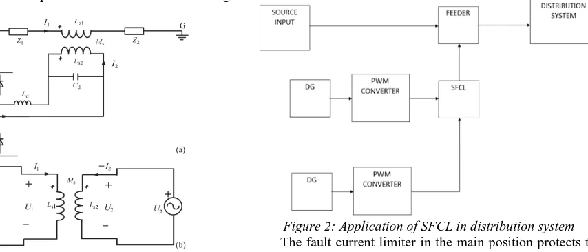
Superconducting fault current limiter offers idyllic performance in electrical power system. SFCL have been attention for many years and propose an efficient method for restrictive the fault current. This is very striking in a distribution system with distributed generated units. This paper describes the possible appliance of fault current limiter. It is shown that the SFCLs, even with relatively small impedance are highly effective at reducing potential fault current. The main applications of superconducting fault current limiter is in the main position, feeder position and in the bus-tie position.
Figure 2: Application of SFCL in distribution system
Page 53 www.ijiras.com | Email: [email protected] coupled, yet faulted bus receives the full fault current of only
one transformer. The air-core superconducting transformer has many compensation such as magnetic saturation, absences of iron losses and also opportunity of diminution in weight, size than the conventional iron-core transformers.
Superconducting fault current limiter comprised of PWM converter and air core superconducting transformer. In this simulation, fault current diminution can mainly depends on superconducting transformer. Transformers represent one of the oldest and most mature elements in the power transmission and distribution network. The air core superconducting power transformer has been investigated as the transformer having the purpose of the shunt reactor which is used to balance the current in the transmission system. However, since the air core superconducting transformer has no special paths for the magnetic flux, its winding has possibility of being exposed to a higher magnetic field than those of the iron core transformer. With the improvement of high temperature superconducting practical presentation and application growth of superconducting transformer have been progressed actively in the world.
IV. SIMULATION STUDY
For the reason of restricting the fault current and overvoltage repression, SFCL is created in MATLAB. The SFCL model was implemented by integrating simulink and simpowersystem block in MATLAB. Simulink and simpowersystem has number of compensation over its up to date simulation software due to its open construction, a powerful graphical user interface and flexible investigation and graphic tools. In this simulation, fault is injected in the source side. By using the superconducting fault current limiter fault current and overvoltage can be restrictive. In compare to conventional technologies, SFCL provides quicker response time, shorter recovery time and time adjustable response functions.
Figure 3: simulation diagram
When a fault duty trouble occurs, regularly more than one breaker will be affected. upgrading of these breakers has the drawback of not reducing the available fault current and
overvoltage. For this reason we have simulated SFCL in MATLAB, to restrictive the fault current and overvoltage.
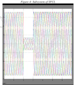
In simulink diagram, the subsystem of SFCL mainly consists of linear transformer. The subsystem of superconducting fault current limiter includes:
Figure 4: Subsystem of SFCL
Figure 4: Input voltage
V. RESULT
Page 54 www.ijiras.com | Email: [email protected]
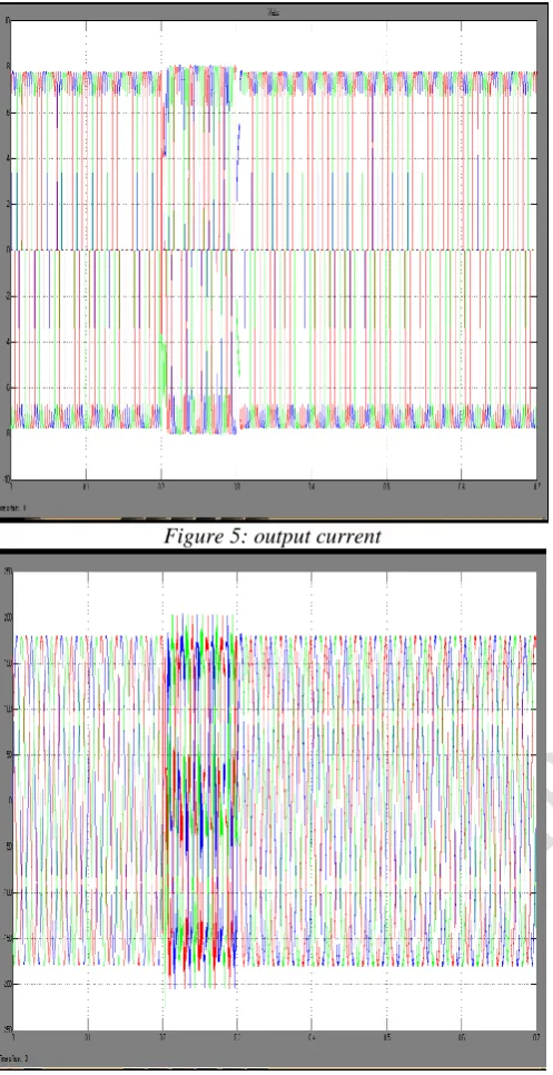
Figure 5: output current
Figure 6: output voltage
Because of the injected fault current, there is some sag is introduced in the circuit. In this output voltage and current values, sag is compensated into normal values.
VI. CONCLUSION
Electric power disruptions cause hundreds of millions of worth of economic loss of every year to the world’s leading economies. With increase in generation, comes an increase in short circuit current in a transmission and distribution system during fault condition. Utilities usually predict how much fault current exists in the line and can forecast its increase over a period of time. This paper presented a reducing the fault current and overvoltage limitation in a distribution system by using superconducting fault current limiter. From the result of analysis fault current can be reduced and suppression of
overvoltage can be done. The main objective of this is to reduce the ratio of overvoltage to normal voltage by using superconducting fault current limiter. Therefore, the study of coordinated control method for the renewable energy sources and the SFCL becomes very meaningful, and it will be performed.
REFERENCES
[1] S. Conti, “Analysis of distribution network protection issues in presence of dispersed generation,” Elect. Power Syst. Res., vol. 79, no. 1, pp. 49-56, Jan. 2009.
[2] A. S. Emhemed, R. M. Tumilty, N. K. Singh, G. M. Burt, and J. R. McDonald, “Analysis of transient stability enhancement of LV-connected induction microgenerators by using resistive-type fault current limiters,” IEEE Trans. Power Syst., vol. 25, no. 2, pp. 885-893, May 2010.
[3] S.-Y. Kim and J.-O. Kim, “Reliability evaluation of distribution network with DG considering the reliability of protective devices affected by SFCL,” IEEE Trans. Appl. Supercond., vol. 21, no. 5, pp. 3561-3569, Oct. 2011.
[4] S. A. A. Shahriari, A. Yazdian, and M. R. Haghifam,“Fault current limiter allocation and sizing in distribution system in presence of distributed generation,” in Proc. IEEE Power Energy Soc. Gen. Meet., Calgary, AB, Canada, Jul. 2009, pp. 1-6.
[5] S. Hemmati and J. Sadeh, “Applying superconductive fault current limiter to minimize the impacts of distributed generation on the distribution pro-tection systems,” in Proc. Int. Conf. Environ. Electr. Eng., Venice, Italy, May 2012, pp. 808-813.
[6] S.-H. Lim, J.-S. Kim, M.-H. Kim, and J.-C. Kim, “Improvement of protection coordination of protective devices through application of a SFCL in a power distribution system with a dispersed gener- ation,” IEEE Trans. Appl. Supercond., vol. 22, no. 3, p. 5601004, Jun. 2012.
[7] L. Chen, Y. Tang, J. Shi, and Z. Sun, “Simulations and experimental analyses of the active superconducting fault current limiter,” Phys. C, vol. 459, no. 1/2, pp. 27-32, Aug. 2007.
[8] L. Chen, Y. Tang, J. Shi, Z. Li, L. Ren, and S. Cheng, “Control strategy for three-phase four-wire PWM converter of integrated voltage com-pensation type active SFCL,” Phys. C, vol. 470, no. 3, pp. 231-235, Feb. 2010.
[9] L. Chen, Y. J. Tang, J. Shi, L. Ren, M. Song, S. J. Cheng, Y. Hu, and X. S. Chen, “Effects of a voltage compensation type active superconducting fault current limiter on distance relay protection,” Phys. C, vol. 470, no. 20, pp. 1662-1665, Nov. 2010.
[10] J. Wang, L. Zhou, J. Shi, and Y. Tang, “Experimental investigation of an active superconducting current controller,” IEEE Trans. Appl. Supercond., vol. 21, no. 3, pp. 1258-1262, Jun. 2011.
Page 55 www.ijiras.com | Email: [email protected] Appl. Supercond., vol. 7, no. 2, pp. 1013-1016, Jun. 1997.
[12] H. Yamaguchi, T. Kataoka, H. Matsuoka, T. Mouri, S. Nishikata, and Y. Sato, “Magnetic field and electromagnetic force analysis of 3-phase air-core superconducting power transformer,” IEEE Trans. Appl. Supercond.,vol. 11, no. 1, pp. 1490-1493, Mar. 2001. [13] M. Song, Y. Tang, N. Chen, Z. Li, and Y. Zhou,
“Theoretical analysis and experiment research of high temperature superconducting air-core transformer,” in Proc. Int. Conf. Electr. Mach. Syst., Wuhan, China,Oct. 2008, pp. 4394-4397.
[14] R. Wu, Y. Wang, Z. Yan, W. Luo, and Z. Gui, “Design and experimental realization of a new pulsed power supply based on the energy transfer between two capacitors and an HTS air-core pulsed transformer,” IEEE Trans. Plasma Sci., vol. 41, no. 4, pp. 993-998, Apr. 2013.
[15] R. Wu, Y. Wang, Z. Yan, Z. He, and L. Wang, “Simulation and experimental investigation of an inductive pulsed power supply based on the head-to-tail series model of an HTS air-core pulsed transformer,” IEEE Trans. Appl. Supercond., vol. 23, no. 4, p. 5701305, Aug. 2013.
[16] S. Chen, W. Wang, and P. Yang, “Effects of current-limiting inductor on power frequency overvoltages in transmission line,” Power Syst. Technol.,vol. 34, no. 3, pp. 193-196, Mar. 2010.