Abstract— This paper deals with an attempt to introduce new terminology in 3D modeling as a result of an effort to increase the speed of machining process and surface finish quality of jewelry master. The effort is addressed two terminologies for CAD CAM data type, those are bitmap-based 3D model and undetermined complex surface. Some issues on jewelry manufacturing problems are related to the effect of those data types.
Unlike in common manufacturing technology, art and jewelry are made in custom order and fabricated manually due to focusing on its beauty and uniqueness. In addition, the demands of exclusive jewelry sharply increased above the productivity of jewelry expert. The application of particular CAD/CAM technology is promising to solve the complexity of jewelry model and its productivity. At this research, a case study of brooch machining has been carried out to show problems. The result showed that machining method achieved ten times faster than manual and three times faster than rapid prototyping. In addition, the cost for creating jewelry master by applying the method is approximately one tenth cheaper than those in manual or by rapid prototyping machine. However, CAD data characteristics should be well understood in order to achieve successful machining.
Index Terms— bitmap-based 3D model, micromachining, relief model, mathematically undetermined complex surface.
I. INTRODUCTION
or decades, art and engineering are considered as two different and separate topics. Art is considered as a touch of feeling resulting in product with unique and beauty, on the other hand engineering has strong characteristics on thinking and analysis which produce goods with good functionality, precision and repetitive [1].
The increase of aesthetic product as response of customer demand accelerates the development of manufacturing technology on aesthetic-based product. One of aesthetic product which meets recent manufacturing trend is jewelry.
Manuscript received January 9, 2012. This work was supported in part by the Indonesia Islamic University and Directorate of Higher Education, Ministry of National Education, BPPS.
Paryana Puspaputra, is a lecturer of Mechanical Engineering Department, Faculty of Industrial Technology - Indonesia Islamic University. Jl. Kaliurang Km 14,5 Jogjakarta- Indonesia 55581. Email: [email protected].
Indra Nurhadi, Yatna Yuwana Martawirya, Arif Basuki, are lecturers of Mechanical Engineering Department, Faculty of Mechanicaland Aerospace Technology, The Bandung Institute of Technology,Jl. Ganeca 10,Bandung – Indonesia.
Jewelry design requires high speed creativity to respond to market demand, and it also requires repetitive design when sizing is a must, like those in ring model. Sizing in ring model is not scaling, because although it has different size in ring diameter, but relief and gemstone at head component cannot be scaled.
Understanding the modeling and manufacturing problem, the use CAD-CAM technology in jewelry manufacturing is a must. There are number of particular CAD-CAM which are dedicated specifically to jewelry design, such as Rhinoceros, Artcam JewelSmith, JewelCad, etc.
Jewelry manufacturing is quite interesting since the product life cycle is about two weeks. That means that during two weeks manufacturer should prepare new design. For an illustration, for medium industry with about 300 workers, its weekly variant is about 200 types of product.
Data from manufacturer showed that preparation time for new product to be ready for mass production (after scratch design is confirmed) is one week.
From the condition mentioned above, jewelry manufacturing requires high speed creativity, high speed production time and high quality surface finish with affordable price.
From production’s point of view, methods to increase jewelry’s productivity are very important. High surface quality, high product variant, and high speed production should be performed by manufacturing section.
Research concerning jewelry manufacturing has been found in several publications. They could be identified and classified into:
- research to increase the ease of jewelry design by introducing parametric modeling [2] and intelligent system [3],
- decision making tools to give index for faster decision making in selecting good design to be manufactured [3], - study of micro casting which discusses the effect of flow rate
of casting to achieve better result in jewelry casting [4][5], - and implementation study of new material for jewelry
master which provide high surface complexity, better surface finish with better production time [6][7].
In this paper, jewelry machining problems due to CAD data structure is discussed. Difference between common engineering CAD model and relief model, by which jewelry model is constructed, is introduced.
Introduction to Bitmap-based 3D Model and
Its Machining Problems.
Case Study: Brooch Machining
Paryana Puspaputra, Indra Nurhadi, Yatna Yuwana Martawirya, Arif Basuki
Bitmap based 3D modeling and undetermined complex surface are introduced as new terminologies in CAD modeling. Those terminologies are very important since they affect significantly to the toolpath generation, machining strategies, and characteristics of machine movements.
II.SCOPESANDLIMITATIONS
This paper will be focused on the discussion of machining problems affected by characteristics of CAD geometrical database which is used particularly in jewelry modeling. Discussion will be limited to problems occurred in the machining of brooch. The aim of the discussion is to explain the importance of understanding the concept of bitmap based 3D model and mathematically undetermined complex surface in order to achieve successful machining in jewelry product. Those two terminologies are introduced in this paper as new terminologies in 3D CAD model.
III. THEORY
III.A. 3D Model and Relief
Software in product modeling can be divided into CAD and non CAD. The difference between CAD and non CAD drawing is in the way their data is stored, that is the CAD database [8] as shown in Fig. 1. In the CAD software, data is stored in the form of database which is completed with necessary information such as unit, material properties, machining information, etc., while non-CAD software usually focused only on geometric information.
Using the database, CAD data can be analyzed, machined and exchanged among them without any significant effort. It is not necessary to re-draw an object when two different applications from different software builder are used.
Although standards for data exchange has been established, it does not mean that data exchange can be done easily, since problems are still found at the process of data exchange [9].
Fig. 1. CAD database
The CAD database is basically consisted of three components, those are geometrical, topological, and text data.
Geometrical data consist of vertex coordinates. Positions of vertices are stored in this type of data.
Topology is defined as relationship between two points, relationship of two planes, inner or outer surface, etc., [10][11][12][13]. Whether three points will construct an arc, a plan, or curve depend on information stored in the topology.
In CAD, text data are divided into two types, those are text as attribute and text as annotation. Attribute text controls for example line type, color, thickness of a line, while annotation text controls whether text is comment, dimension, or explanation of an object in a drawing [11][12][13].
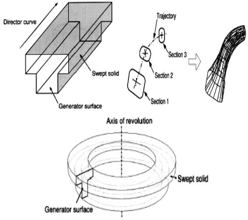
CAD model is usually constructed from mathematical equation. A model is usually combination of primitive geometry or more complex forms with Boolean operation (see Fig. 2. ). Hence, most CAD model are mathematically determined.
Fig. 2. Model generation using sweep operation [14].
Data characteristic in particular CAD/CAM software for jewelry is different from those in engineering product. While CAD in engineering design are usually mathematically determined, CAD in jewelry is stored as points cloud or bitmap based surface data [13] as shown in Fig. 3.
Fig. 3. Bitmap-based model in tooth-brush ’surface’. 3D relief
In art application software, 3D is developed by defining height of each point in a defined area (bitmap) and density. Term of this model is then called as relief [15].
From the relief characteristics, it is understood that the constructed surface is not mathematical representation, because there no mathematical function which define relationships among points.
This type of modeling can be explained as follow: it is initiated with definition of model resolution by defining model area and its bitmap density. Once it is defined, product resolution will always follow the ratio of bitmap/area [15]. The 3D model is the be built by defining the height of points in the area which can be defined by closed vectors or bitmap as shown in Fig. 4.
This preliminary stage is very important to define surface quality of model. Higher bitmap density will result in better surface resolution, but it will enlarge the file size and prolong the machining time..
It is important to define proper surface resolution of product. In this step, information of CNC accuracy and its tool size, or rapid prototyping machine and its grain size should be taken into account. Distance between two adjacent points should not be less than the machine accuracy or smaller than the grain size.
.
(a)(b)
Fig. 4. Model generation based on bitmap height. (a) borders consist of bitmap and vectors, (b) relief generated using borders
When resolution is too dense, or position of two adjacent points is too close, machining time will increase significantly without significant effect on surface finish quality. On the other hand, when the density is too low, machining time will be less, but it will result in lower surface quality of machining.
It should be noted that in bitmap-based model, once the bitmap density is defined and the model is designed, no modification on model density can be made. In the other words, one should begin things from the start when the model is inappropriate.
From the previous discussion, the term of bitmap based 3D modeling means that 3D model is built by the height variation of points in a specified area. Moreover, undetermined complex surface is the term for surface of bitmap based 3D model. This surface is visually similar to other 3D surface, but it consist of only points with no mathematical relation among them.
III.B. CAM in Relief
Computer-aided manufacturing (CAM) is define as the use of computer-based software tools that assists engineers and machinists in manufacturing or prototyping product components. CAM is a programming tool that makes it possible to manufacture physical models using Computer Aided Design (CAD) programs. CAM creates real life versions of components designed within a software package. CAM was firstly used in 1971 for car body design and tooling. [16]
To perform efficient process in CAM, proper approach in tool path programming should be performed. Straight line path should be coded using a linear interpolation, G00 or G01, and circular path should be in circular interpolation, G02 or G03. In the CNC which has capability in spline-interpolation, tool path will not sent to the machine in the form of G-code. It is sent in the form of high order mathematical equation [17].
That mentioned tool path approach is very important to perform high speed machining. The way the tool path is generated will significantly affect machining speed, tool life, surface finish quality, etc. [17].
Referring to the relief characteristics mentioned before, the following machining conditions occur in relief model:
The only approach for tool path is linier interpolation (point to point) movement (G00 or G01). Since the distance between two adjacent points is very small and ‘look forward’ capability in machine controller is limited, feed rate cannot be performed as it is defined in input parameter. The machine should always decelerate before the required speed is achieved.
Software notifies that all points in the defined relief area are object, no feature is recognized. Hence, user should define the limit of machining area, or software will recognize the whole model as machining area. User defined area is very important to control machine movement, machining sequence, etc. Machining sequence may make machining procedure to become more complicated, but it is the effective way to control the strength of rest work piece, tool life, surface quality, etc.
III.C. Micromachining
Micromachining is defined as fabrication of tiny devices: the techniques used in fabricating the miniaturized devices and moving parts into which microelectronic circuitry is integrated (Encarta).
Another definition is made by Seco Tool, 2006, where micromachining is defined as machining strategy where extremely small tool diameters are used. The tool characteristics are: diameter is in the range of 0.1 to 2 mm, small cutting length, high accuracy, coated. Machine requirement are high spindle accuracy, high rpm, thermal stability against spindle growth. The micromachining area is production of cavity, slot, pocket, holes or engraving in many type of material [18].
Fig. 5. Conical tool, flat diameter 0.1mm, half angle 3.5 degree.
According to references, micromachining is usually done in semiconductor manufacturing, bio mechanics, jewelry, etc. Micromachining usually deals with laser cutting, layer manufacturing, chemical machining, etc.
In this paper, micromachining is used in term of machining jewelry master (master) using CNC milling machine with tiny single lip tool with 0.1 flat diameter, 3.5 degree in half angle, and 17000 rpm in spindle rotation as shown in Fig. 5.
IV. EXPERIMENT AND DISCUSSION
IV.A. Object Description
As it is referred to the way the model is developed, points in relief model can be classified into polar or cylidrical and planar or cubical coordinate based positions [7].
Model with polar coordinate system can be found in round type jewelry, such as ring, bracelet, and bangle, while planar model can be found in brooch, pendant, watch, etc.
Machining problems in polar coordinate relief model has been discussed in earlier paper. Surface finish quality affected by tool geometry and machining strategies has already been discussed. Moreover, the effect of work-piece origin’s shifting to geometric accuracy on machining result has also already been highlighted [7].
An effort to identify machining problems on planar or cartesian model has been done, a case study in machining of a
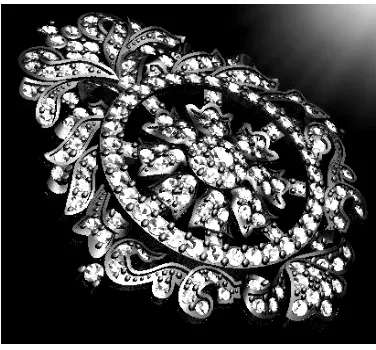
brooch model with outer dimension about 70x45x15 mm and 0.7 mm in wall thickness, will be arranged with 2.25 mm diamonds as it showed in Fig. 6. will be discussed.
Fig. 6. Brooch model
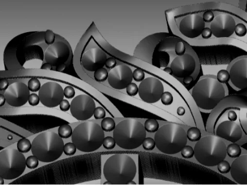
From the description of the object, it is understood that the diamond should be arranged properly. The beauty of the brooch, which depends on the brightness of beam reflection of the diamonds are highly depend on the diamond’s arrangement as shown in Fig. 7.
Fig. 7. Brooch model with diamond attached
Manual diamond attachment is very difficult since distances between two adjacent diamonds should equal, the number of diamonds should met with profile length, etc.
Fig. 8. Diamonds arrangement and pronges (zoomed)
Moreover, it can be informed that manual arrangement of diamonds and pronges for similar model took about a month, but CNC machining reduces those processing time to be less than 30 hours.
IV.B. Tool and Machining
As model is in planar or 3D flat model, then flip machining is conducted. Upper part is firstly machined, and then work-piece is flipped 180 degree for another side machining.
The machining process is divided into several steps, roughing step to reduce work-piece volume as much as possible, semi finishing to let cutting tool approaching the final form and ended with finishing. The aim is to produce master model with high quality surface finish, and perform machining process as fast as possible.
Roughing is done by using two sub-steps that use different diameter size of end mill tool. No specific machining parameters in this process.
Semi finishing step is to reduce more material to get closer to product dimension. In this step ball-nose tool diameter from 1 mm and 0.5 mm is respectively used. At the last process, semi finishing using conical tool with 0.5 mm in flat radius and 5 degree half angle is used.
Finishing step is the most critical. To achieve high quality surface finish and perfect geometry, 0.1 mm flat radius with 3.5 degree half angle of conical tool as previously shown in Fig. 5. is used.
IV.C. Machining Problems and Discussion
1) Machining Simulation
In order to be able to achieve good result, cutting tool movement for each tool diameter should be firstly simulated. Fig. 9. shows the result of machining simulation after finishing process.
Using the simulation, some problems can be detected before it causes serious problem during implementation. Simple problem may be the evaluation of final shape of workpiece after finishing. There are problems which can be identified by simulation: whether desired relief can be cut using selected
tools, kind of tools appropriate to achieve final form, cutting sequence, etc.
Furthermore, deeper evaluation can also be done by evaluating for example the strength of the workpiece construction, bridge construction, recommended machining sequence, machining strategies, etc.
Fig. 9. Machining simulation result: a) Cross section view, b) Isometric view, c) workpiece.
Following is an example of the evaluation at earliest step of machining. Roughing process is conducted with end mill tool which has 2mm in diameter,
In roughing step, machining will reduce workpiece volume as fast as possible. Portion of the workpiece (e.g. circumference or bridge, Fig. 9. ) may tend to achieve final thickness at roughing step due to their wide and flat area,, while other portion may still thick.
The thin area is very critical, for the ongoing machining or for the next coming process. Workpiece may be broken when cutting force exceeds the strength of thin structure. To avoid that, machining sequence should be controlled by using simulation step.
2) Machining the Holes
From Fig. 9. , it can be seen that holes in the relief model are not considered as “blank” area, but they are identified as relief with undefined height.
The bitmap-based 3D model also cannot identify features, as a result tool will move according to the defined machining strategy and closed vector under which machining is done.
Simplified model and its cross section of the object is shown in Fig. 10. to illustrate tool path movement in relief with holes.
In cross section, holes is shown as line with zero height. Depends on the distance between holes and its adjacent relief, drastic change on relief height can be narrow or wide.
Assuming that tool is moved along X axis with 10 m/s of feed rate. CNC will keep its movement at that defined feed rate and move point to point (since surface of relief is mathematically undetermined). As a result, when there is sudden change in Z position, machine will move very fast in Z direction to keep speed in X direction.
That high speed movement become crucial, and may occur in any stage of machining (roughing or finishing). Condition becomes critical because work-piece become weak by previous stage of machining process or generated cutting force exceeds the strength of work-piece or cutting tool.
Fig. 10. Simplified model and its cross-section
Moreover, when small size tool is used, the tool’s cutting length is very limited. When relief height is greater than cutting length, the work-piece may be broken because tool shank and work-piece will collide (Fig. 11. ).
Fig. 11. Tool-holder and workpiece Collision
3) Machining the Sharp Edges
Another machining phenomenon can be analyzed by using Fig. 12. Complex aesthetical geometry can be simplified by using model with star form as object geometry. Star form representing object with various sharpness. Circle form in the Fig. 12. represents cross section area of various cutting tool size.
Cutting tool will move to the depth of the star only when its cross section is smaller than cut area, or when it is greater, it will leave object uncut. When the relief is sharp, tiny tool radius is necessary to get close to required shape.
Fig. 12. Cutting phenomena in simplified model.
Those sharp forms are common in jewelry, where sharp and narrow edges are used to show that the manufacturer has high capability to produce high quality and complexity product [19].
Since uncut area always occurs even in very small area, finishing process that usually use tiny tool should take care on that. Tiny tool is very critical from cutting force. The higher the speed is, the higher rate of material removal and higher cutting force will occur which potentially breaks the tool, on the other hand, lower speed will result in longer machining time.
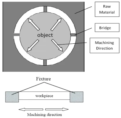
4) Machining from Strongest to Weakest Structure
Structure of an object and its fixture can be considered as a beam with simple support (Fig. 13. ). As machining is a process of volume reduction, it will also reduce the strength of the work piece structure.
Fig. 13. Machining direction, strength of work-piece should be considered.
The rest of the material should strong enough to handle forces resulted from machining process. Machining strategy should be done by considering this. Machining sequence should be controlled to ensure that the weakest position is machined prior to the stronger position. In this brooch machining, cutting process should be started from the center of the work-piece and finished at the outer edges.
holes
IV.D. Machining Result
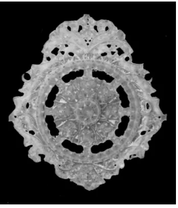
Considering condition mentioned previously, machining of a brooch master is done and the result is showed in Fig. 13. The overall machining time is about 20 hours and successfully machined after 4 times trial.
The result however should be processed with de-burring process to clean up the work-piece from particle or chip which stuck to the work-piece by electrostatic magnet or glued because of tool and workpiece friction and cutting temperature that melt them.
As compared to hand-made process, time consumed in brooch machining is 30 times faster, and it is 3 times faster when compared to rapid prototyping.
Fig. 14. Machining result
Machining and hand-made process could produce master directly. On the other hand rapid prototyping result cannot be used directly as a master since surface quality is not enough. Improvement is done by investment casting using metal, usually silver, by which final master quality is achieved.
Considering the overall cost for master preparation, including finishing process and material, machining is the most economical. It is about one tenth as compared to manual and rapid prototyping.
V.CONCLUSIONS
Characteristic of data stored in the geometrical digital model plays important role in machining performance.
To perform aesthetic design, jewelry is modeled as complex surface. 3D model is approached by bitmap-based 3D modeling and the surface of the model become undetermined complex surface.
Those type of 3D surface model brings problems when it is machined, those are:
- Since the 3D data is only collection of points, only point to point (G01,or linear interpolation approach can be performed in tool path generation. This brings
inefficiencies in machining speed, since maximum machine speed cannot be utilized.
- There is no information about normal vector, hence machine which utilizes normal vector of surface (5 axes) cannot be utilized to improve surface finish quality. - There is no feature in this type of 3D model. Hole is
identified as surfaces with zero height. Care should be taken when machining object with holes. Movement with uncontrollable speed may occur and collision between tool and workpiece may be happened.
Moreover, model is usually very thin, hence machining sequence should be controlled to keep workpiece strong enough from cutting forces during machining.
Machining process for master preparation offers better capability to produce more complex surfaces, less time consumption, and cheaper cost. The disadvantage is that it needs advance understanding in CAD/CAM and machining technology.
FUTUREWORKS
There is a need for the development an artificial intelligent program to recognize pattern in relief model. Pattern recognition program which can identify holes, bridge, etc., can be used to help operator to simplify machining sequences and strategies in order to achieve successful machining on jewelry product.
ACKNOWLEDGEMENT
The author would like to appreciate and thank to Universitas Islam Indonesia and BPPS (Directorate of Higher Education, the Ministry of National Education) for supporting this research.
REFERENCES
[1] Puspaputra, Paryana, 2009. Pengembangan Metoda Pemesinan
Permukaan Kompleks Berbasis Bitmap. Proposal Disertasi,
JurusanTeknikMesin ITB, Bandung.
[2] Vasiliki Stamati, Ioannis Fudos. A Parametric Feature-based CAD
System for Reproducing Traditional Pierced Jewellery. Elsevier, July
2004.
[3] Wannarumon, S. and Bohez, L.J, Kittinan Annanon. Aesthetic
Evolutionary Algorithm for Fractal-based User-centered Jewelry Design. Artificial Intelligence for Engineering Design, Analysis and
Manufacturing, Cambridge University Press New York, NY, USA, January 2008.
[4] Patrizio Sbornicchia, et.al. Advances in Jewellery Microcasting Elsevier, December 2003).
[5] .Zhang, et.al. Gold Jewellery Casting: Technology Design and Defects
Elimination (Elsevier, Singapore, 1995)
[6] Puspaputra, Paryana, et.al. The Application of CAD/CAM Technology
for Small Industries in Developing Creative Cultural Design of Art and Jewelry. Proceeding of The 9th Asia Pacific Industrial
Engineering & Management Systems Conference, Bali 2008. [7] Puspaputra, Paryana.et.al.,2010. Micro-machining Problems in
Undetermined Complex Surface (Case Study: Machining of Jewelry’s Master Model), The 11th Asia Pacific Industrial Engineering and Management System Conference (APIEMS) 2010, Malaka, Malaysia. [8] Puspaputra Paryana, Erlangga Fausa. Development of Customer
Support Application for Engraved Furniture Design, Proceeding of
[9] Amaitik, Saleh. Step Feature-Based Intelligent Process Planning
System for Prismatic Parts. The Eleventh International Conference on
Machine Design and Production, 13 - 15 October 2004, Antalya, Turkey.
[10] Avibank Mfg., Inc., CAD/CAM/CAI Quality Plan / Procedure, 2001. [11] Groover, M, P, 1987. CAD/CAM : Computer Aided Design and
Manufacturing. Prentice Hall of India. New Delhi.
[12] Topology, Spatial Relationship.
http://www.edc.uri.edu/nrs/classes/NRS409/Lectures/3GISdefined/top ology.gif, 21Januari 2009.
[13] Tien-Chien Chang, et.al, Computer-Aided Manufacturing, Prentice Hall, 2005.
[14] Lee K., 1999. Principles of CAD/CAM/CAE Systems, Addison-Wesley.
[15] Delcam Plc. ArtCAM Referece Guide. Birmingham, 2002. [16] Software Solutions (Chennai) Pvt. Ltd.
http://www.htssindia.in/CAM.aspx accessed on 6th January 2012. [17] Puspaputra, Paryana. PeranPentingTeknologi NURBS pada Proses
PemesinanKecepatanTinggi. Media Mesin.
UniversitasMuhammadiyah Surakarta, Januari 2000. [18] Seco Tool, Jabro Catalog, 2006.
[19] Newman, Renee. Jewelry Handbook. How to Select, Wear & Care for
Jewelry. International Jewelry Publications, Los Angeles, 2007.
Paryana Puspaputra was born in Kotabumi on January 19, 1964.
Recently he is a Lecturer at the Department of Mechanical Engineering, Faculty of Industrial Technology, Indonesia Islamic University - Indonesia. Undergraduated from Department of Mechanical Engineering, Bandung Institute of Technology, Indonesia (ITB) in 1990 and got master degree in Mechanical Engineering Department of Nagaoka University of Technology, Japan in 1996.
He is now taking doctorate degree at Mechanical Engineering Department, Institut Teknologi Bandung, Bandung – Indonesia. His research in jewelry manufacturing is started in 2002, and his knowledge in CNC is achieved during his one year training at Okuma & Howa Machinery, Japan 1992-1993. His email address is<[email protected]>.
Indra Nurhadi is a Professor at Mechanical Engineering Department,
Institut Teknologi Bandung, Bandung – Indonesia. He was born in Madiun, on May 26, 1947. Undergraduate from Mechanical Engineering Department, Institut Teknologi Bandung, Bandung in 1973. He received master degree at Mechanical Engineering Department, University of Wisconsin – Madison, USA in 1981 and doctorate degree from the same university in 1985. His email address is<[email protected]>.
Yatna Yuwana Martawirya is a Professor at Mechanical Engineering