© 2016 IJSRSET | Volume 2 | Issue 2 | Print ISSN : 2395-1990 | Online ISSN : 2394-4099 Themed Section: Engineering and Technology
Underground Material Handling Using PLC and HMI
Sandiya V, Tharani A, Vishvatharani N, Yuvashri J, Mithunraj S
Department of Electronics and Communication Engineering, Sri Eshwar College of Engineering Coimbatore, Tamilnadu, India
ABSTRACT
Underground material handling using Programmable Logical Controller & Human Machine Interface helps us to hold the materials (books) which are stored in underground will be taken above the ground if necessary with the help of Two Access Robotic Arm. Nowadays each and everything is getting smarter in its own way. We used to store the excess materials in a store room or in some other place from where we can access it in support of upcoming use and it needs man power. Instead of using man power, here we are using automation to access the materials. Storing materials in the underground is an effective method. In this project HMI acts as an input unit as well as a display unit, it helps us to give the input to proceed with the process. PLC is used to control the process with the help of coding. Books are stored in racks under which there is a moving bed and the two access robotic arm is used to pick and place the book in a moving bed (base plate). The working of the base plate’s movement and two access robotic arm’s forward, reverse, pick and place actions are controlled by DC motors.
Keywords: HMI, PLC, RELAY CARDS, MCB
I.
INTRODUCTION
Nowadays everything is getting smarter in its own unique way. Even for living people are using lesser and compact space. From olden days till now we are using store rooms or lofts to store excess materials which we need for future use. In all these concepts manpower is needed to get that material when necessary. In this modern world,we are leading a machine life so we cannot go and refill the materials all the time. So we are going for automation, In this project we are using a programmable logical controller and human machine interface to clutch the materials (books) that are stored in underground. We are using two access robotic arm and dc motors for this operation. For example, in a college library when all the books in a rack have been taken by the students, the rack becomes empty and there are no books available on that rack. At this time we can get the books which we have stored in underground to fill the rack using this project.
In this paper we are using PLC to direct the robotic movements. Programmable Logic Controller (PLC) is a tiny PC used for mechanization of real -world processes,
such as mastery of machinery on factory assembly lines. The PLC mostly propapally uses the microprocessor. The program can often manage by the intricate sequencing and is frequently written by engineers. All the information stored inside the program is password protected and/or EEPROMs. Distinctly commonly-used computers, the PLC is package and planned for unlimited temperature range, filthy or sandy environment, resistance to electrical clatter, and is automatically more rough and opposing to quivering and impact. By implementing this project we reduces male power, thus increase in production of the industry.
II.
METHODS AND MATERIAL
A. Existing System
components, such as a DC motor regulator and direct pendent. The parts particular be individuals that met specifications and designed requirements. The majority of the time was spent on wiring and installation. During the installation, consideration was made for a safe and effective design. In this project, the robotic arm is used to reduce the manpower to refill the materials. After the complete installation of all the hardware sections, the programming was the last to be completed. The principles for manual modes of operation and automatic modes of operation were described exhaustively in the programming part of this thesis. All the parts of the control system; i.e the hardware part and the programming part were accomplished with a successful demonstration. The composite encoding be feasible in the PLC for the automatic mode of operation. It was establish with the intention of a Robotic Arm with a easy machine can be manipulated in a different complex way by using a PLC.
1. Time spent forming and breaking down the unit load.
2. Cost of containers/pallets and other mass preventive equipment used in the unit load
3. Empty containers/pallets may possibly need to be returned to their point of origin.
B. Proposed System
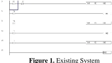
The foremost PLCs were programme with a procedure that was based on relay logic electric wiring schematics. This eliminated the need to instruct the electricians, technicians and engineers how to ’program’ a computer - but, this method has stuck and it is the most common method for training PLCs today. To interpret this diagram visualize that the control is on the perpendicular line on the left hand side, we describe this the hot bar. On the right hand side is the impartial bar. In the figure there are two rung and on each rung there are combination of input (two perpendicular lines) and output (circles). If the inputs are opened or closed in the right arrangement the power can flow from the warm bar during the input, to power the output, and at last to the impartial bar. An input can come from a sensor, knob, or any other type of sensor. An output will be a few tool outside the PLC that is toggle on or off, such as illumination or motors. In the peak step the contacts are normally open and normally closed. Which means if input ’A’ is on and input ’B’ is off, then power will run
throughout the output and activate it. Some other grouping of input standards will outcome in the output ’X’ being off.
Figure 1. Existing System
Ladder Logic Inputs
PLC inputs are simply represented in ladder logic. There are three types of inputs. The first two are normally open and normally closed inputs, discussed earlier. The ’IIT’ (Immediate Input) task allow input to be examine behind the input scan, while the ladder logic is being scanned. This allows ladder logic to examine input values more often than once every cycle. Normally open, an active input x will close the contact and allow power to flow. Normally closed, power flow when the input x is not open. Instant input will take current values, not those from the previous input scan. (Note: this instruction is actually an output that will update the input table with the current input values. Other input contacts can currently be used to examine the new values.)
Ladder Logic Outputs
of a ’U’ output. The last instruction is the ’IOT’ (Immediate Output) that will allow outputs to be updated without having to wait for the ladder logic search to be completed. Normally open, an active input x will close the contact and allow power to flow. Normally closed, power flow when the input x is not open. Immediate inputs will take current values, not those from the previous input scan. (Note: this instruction is actually an output that will update the input table with the current input values. Other input contacts be able to observe the new values).
Figure 2. Block Diagram
HMI is a device, that provides interface between the user and machine. It act as an input and display unit. The input at HMI is interfaced with PLC controlling unit. Two axis robotic arm is used to pick and place the material and the actions of the arm is controlled by DC motor.
Figure 3. HMI DEVICE
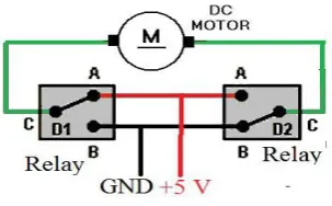
In any electric motor operation is based on trouble-free electromagnetism. A current-carrying conductor generate a magnetic field when this is then placed in an peripheral magnetic field, it will experience a force proportional to the current in the conductor and to the strength of the peripheral magnetic field.
The internal configuration of a dc motor is planned to control the magnetic interface among a current carrying
conductor and an peripheral magnetic field to generate rotational motion.
Components Requirements
HMI-Human Machine Interface acts as a input and display unit.HMI is interfaced with PC by using USB to slave. This device is also interfaced with PLC by using RS-232 .
PLC-Programmable Logic Controller is used to control the motor by using coding (ladder diagram).
ROBOTIC ARM-Two axis robotic arm is used to pick and place the materials, which is controlled by motor.
DC MOTOR-Here four dc motors are used, two dc motors are used for movement of base plate and another two dc motors are used for robotic arm for pick and place the materials.
Hardware Requirements
DELTA HMI
Figure 4. DELTA HMI
SD Card
SD card (supports SDHC) can be used to save and transmit data. The following folder set-up is FAT32. Before using a SD card, reformatting (FAT32) via HMI is required. Only SD card that formatted by HMI can be used on both HMI and Windows® OS system. (Still it can be read/write in several design, but fault may occur due to dissimilar design among Win95/98/2000/XP versions)
USB disk can be used to save data. It also can be used to copy data from HMI and its set-up is FAT32 as well. When using USB floppy to save data, were commend that the storage capacity should be less than 2GB and the users should enter system screen first and then remove the USB diskette. Follow this process can make sure that the data is saved completely in USB disk.
There are two kinds of methods for removing the USB diskette:
1. Press SYS button for 3 seconds to enter into the system setting screen. Then, the users could choose the function to remove the USB diskette.
2. Create a “Remove storage” button on the screen first. After settings and compile operation is completed, pressing this button is able to remove the USB diskette.
The above two methods to eliminate the USB diskette to make sure that the data is saved completely in USB disk.
Control Panel
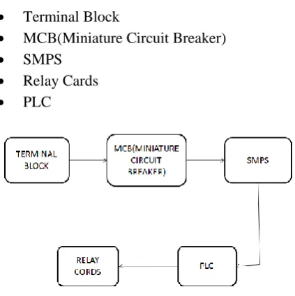
Terminal Block
MCB(Miniature Circuit Breaker) SMPS
Relay Cards
PLC
Figure 5. Control Panel Diagram
Terminal Block
Terminal block is used for looping purpose. A terminal block is a screw type electrical connecter was the wires are clamped down to the metal part by a screw. It is a connector which allows above one circuit to connect to another circuit.
Figure 6. Terminal Block
MCB
MCB acts as a automatic switch and it controls over voltage. Circuit breakers provide a physical means of stimulating and de-energizing a circuit and regular over current production.
An overload takes place when too many devices are operated on a particular circuit or when electrical equipment is made to work beyond its rated capabilities.
When an over load occurs, break to coupled apparatus or the conductors that furnish that apparatus can occur if the circuit is blackout by an over current production device.
Figure 7. MCB Modern Board
SMPS
Figure 8. SMPS Block Diagram & Model
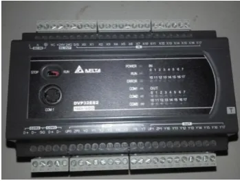
PLC
The converted dc voltage is given to plc.
A digital electronic tool that uses a programmable memory to accumulate instruction and to execute function such as logic, sequencing, timing, counting and arithmetic with the intention of manage equipment and processes. The word logic is use primarily disturbed with implementing logic and switching operations .Input devices e.g. switches, and output devices e.g. motors, being prohibited are coupled to the PLC and then the organizer monitor the input and output according this series stored in the PLC by the operator and so controls the machine .
Figure 9. Digital PLC Board
Relay Cards
Relay is an electromechanical device that is actuate by an electrical current.The current flow in one circuit cause the opening or closing of a different circuit.
Relays are like remote control switches and are used in several purpose because of their relative effortlessness, durability and proven high consistency.
Figure 10. Relay Cards
Wiring Connection
Figure 11. Connection Diagram
III. RESULTS AND DISCUSSION
HMI
Figure 12. HMI Window
DOP-B07S415.This support multiple languages and is easy to program and create screen for your delta HMI’s.
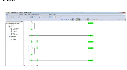
PLC
Figure 13. Simulation Window
DELTA PLC screen editor version is WPL SOFT version 2.41 and model is DVP32ES2.
Programmable logic controller (PLC) is a type of digital processor that has an input and an output crossing point, controlled by a simulated program designed in a computer and it is used for mechanization for electromechanical process, typically for industrial use. In industry, PLCs are made to control the machinery of production lines. A PLC is intended for numerous input and output activities and these inputs and outputs are reasonably programmed in altered forms, such as a ladder diagram, a structural text and a efficient block diagram and stored in the PLC’s memory. PLCs are reprogrammable and it can have monitors online to know the position of the operation. A PLC is an example of a rigid real time system since output results must be formed in reaction to input setting within a restricted time, or else an unintended operation will result.
IV. CONCLUSION
The soft wiring advantage provided by programmable controllers is Tremendous. In fact, it is one of the most fundamental description of PLCs. Soft wiring make change in the control system simple and cheap. If it want a apparatus in a PLC system to perform in a different way or to control a altered method component, all have to do is change the control Program. In a traditional system, making this type of change would involve physically varying the electric wiring between the devices, a costly and time-consuming effect. In future definitely PLC is dominated on all other controlling methods.
V.
REFERENCES
[1] Dasari, Siva Kali Prasad, "Sensor Based PLC
Programming for a Discrete Event Control
[2] Parker Hannifin Corporation Electromechanical
Automation Division Irwin, Pennsylvania [2]
[3] S7-200 Programmable Controller System Manual
Edition 09/2007 A5E00307987—03 [3], [4]
[4] PLC-SCADA Based Automated Logistics