Release 2.0.1
Peter L Dordal
0 Preface 3
0.1 Second Edition . . . 3
0.2 Licensing. . . 4
0.3 Classroom Use . . . 5
0.4 Acknowledgments . . . 7
0.5 Progress Notes . . . 8
0.6 Technical considerations. . . 8
0.7 A Note On the Cover . . . 10
0.8 Recent Changes . . . 11
1 An Overview of Networks 13 1.1 Layers . . . 13
1.2 Data Rate, Throughput and Bandwidth . . . 14
1.3 Packets . . . 14
1.4 Datagram Forwarding . . . 15
1.5 Topology . . . 18
1.6 Routing Loops . . . 19
1.7 Congestion . . . 20
1.8 Packets Again . . . 21
1.9 LANs and Ethernet . . . 22
1.10 IP - Internet Protocol . . . 24
1.11 DNS . . . 30
1.12 Transport . . . 30
1.13 Firewalls . . . 34
1.14 Some Useful Utilities. . . 35
1.15 IETF and OSI. . . 37
1.16 Berkeley Unix . . . 40
1.17 Epilog. . . 40
1.18 Exercises . . . 40
2 Ethernet Basics 45 2.1 10-Mbps Classic Ethernet . . . 46
2.2 100 Mbps (Fast) Ethernet . . . 57
2.3 Gigabit Ethernet . . . 58
2.4 Ethernet Switches . . . 59
3 Advanced Ethernet 67
3.1 Spanning Tree Algorithm and Redundancy . . . 67
3.2 Virtual LAN (VLAN) . . . 72
3.3 TRILL and SPB . . . 76
3.4 Software-Defined Networking . . . 78
3.5 Epilog . . . 84
3.6 Exercises . . . 84
4 Wireless LANs 89 4.1 Adventures in Radioland. . . 89
4.2 Wi-Fi . . . 93
4.3 WiMAX and LTE . . . 120
4.4 Fixed Wireless . . . 123
4.5 Epilog . . . 126
4.6 Exercises . . . 126
5 Other LANs 129 5.1 Virtual Private Networks. . . 129
5.2 Carrier Ethernet . . . 130
5.3 Token Ring. . . 131
5.4 Virtual Circuits. . . 132
5.5 Asynchronous Transfer Mode: ATM . . . 136
5.6 Epilog . . . 138
5.7 Exercises . . . 138
6 Links 143 6.1 Encoding and Framing. . . 143
6.2 Time-Division Multiplexing . . . 148
6.3 Epilog . . . 153
6.4 Exercises . . . 153
7 Packets 155 7.1 Packet Delay . . . 155
7.2 Packet Delay Variability . . . 158
7.3 Packet Size . . . 159
7.4 Error Detection. . . 161
7.5 Epilog . . . 166
7.6 Exercises . . . 167
8 Abstract Sliding Windows 171 8.1 Building Reliable Transport: Stop-and-Wait . . . 171
8.2 Sliding Windows. . . 176
8.3 Linear Bottlenecks . . . 179
8.4 Epilog . . . 187
9.2 Interfaces. . . 196
9.3 Special Addresses . . . 198
9.4 Fragmentation . . . 199
9.5 The Classless IP Delivery Algorithm . . . 201
9.6 IPv4 Subnets . . . 205
9.7 Network Address Translation . . . 210
9.8 Unnumbered Interfaces . . . 215
9.9 Mobile IP . . . 216
9.10 Epilog. . . 218
9.11 Exercises . . . 218
10 IPv4 Companion Protocols 221 10.1 DNS . . . 221
10.2 Address Resolution Protocol: ARP . . . 232
10.3 Dynamic Host Configuration Protocol (DHCP) . . . 236
10.4 Internet Control Message Protocol . . . 238
10.5 Epilog. . . 241
10.6 Exercises . . . 241
11 IPv6 243 11.1 The IPv6 Header . . . 244
11.2 IPv6 Addresses . . . 245
11.3 Network Prefixes . . . 247
11.4 IPv6 Multicast . . . 249
11.5 IPv6 Extension Headers . . . 249
11.6 Neighbor Discovery . . . 252
11.7 IPv6 Host Address Assignment . . . 256
11.8 Epilog. . . 261
11.9 Exercises . . . 261
12 IPv6 Additional Features 263 12.1 Globally Exposed Addresses . . . 263
12.2 ICMPv6. . . 263
12.3 IPv6 Subnets . . . 265
12.4 Using IPv6 and IPv4 Together . . . 266
12.5 IPv6 Examples Without a Router. . . 270
12.6 IPv6 Connectivity via Tunneling . . . 273
12.7 IPv6-to-IPv4 Connectivity . . . 276
12.8 Epilog. . . 278
12.9 Exercises . . . 278
13 Routing-Update Algorithms 279 13.1 Distance-Vector Routing-Update Algorithm . . . 280
13.2 Distance-Vector Slow-Convergence Problem . . . 284
13.3 Observations on Minimizing Route Cost. . . 286
13.4 Loop-Free Distance Vector Algorithms . . . 288
13.7 ECMP. . . 299
13.8 Epilog. . . 300
13.9 Exercises . . . 300
14 Large-Scale IP Routing 307 14.1 Classless Internet Domain Routing: CIDR. . . 307
14.2 Hierarchical Routing . . . 309
14.3 Legacy Routing . . . 310
14.4 Provider-Based Routing . . . 311
14.5 Geographical Routing . . . 316
14.6 Epilog. . . 317
14.7 Exercises . . . 317
15 Border Gateway Protocol (BGP) 321 15.1 AS-paths . . . 322
15.2 AS-Paths and Route Aggregation . . . 324
15.3 Transit Traffic. . . 325
15.4 BGP Filtering and Routing Policies . . . 325
15.5 BGP Table Size . . . 327
15.6 BGP Path attributes. . . 328
15.7 BGP and Traffic Engineering. . . 332
15.8 BGP and Anycast. . . 335
15.9 BGP Relationships . . . 335
15.10 Examples of BGP Instability . . . 339
15.11 BGP Security and Route Registries . . . 341
16 UDP Transport 347 16.1 User Datagram Protocol – UDP . . . 347
16.2 Trivial File Transport Protocol, TFTP . . . 359
16.3 Fundamental Transport Issues . . . 361
16.4 Other TFTP notes. . . 366
16.5 Remote Procedure Call (RPC) . . . 368
16.6 Epilog. . . 372
16.7 Exercises . . . 372
17 TCP Transport Basics 377 17.1 The End-to-End Principle . . . 378
17.2 TCP Header. . . 378
17.3 TCP Connection Establishment . . . 380
17.4 TCP and WireShark . . . 384
17.5 TCP Offloading. . . 386
17.6 TCP simplex-talk . . . 386
17.7 TCP state diagram . . . 391
17.8 Epilog. . . 396
18.2 TIMEWAIT. . . 402
18.3 The Three-Way Handshake Revisited . . . 403
18.4 Anomalous TCP scenarios . . . 405
18.5 TCP Faster Opening . . . 406
18.6 Path MTU Discovery . . . 406
18.7 TCP Sliding Windows . . . 407
18.8 TCP Delayed ACKs . . . 407
18.9 Nagle Algorithm . . . 408
18.10 TCP Flow Control. . . 408
18.11 Silly Window Syndrome . . . 409
18.12 TCP Timeout and Retransmission . . . 410
18.13 KeepAlive . . . 411
18.14 TCP timers . . . 411
18.15 Variants and Alternatives . . . 411
18.16 Epilog . . . 421
18.17 Exercises . . . 421
19 TCP Reno and Congestion Management 423 19.1 Basics of TCP Congestion Management . . . 424
19.2 Slow Start. . . 428
19.3 TCP Tahoe and Fast Retransmit . . . 433
19.4 TCP Reno and Fast Recovery . . . 434
19.5 TCP NewReno . . . 437
19.6 Selective Acknowledgments (SACK) . . . 439
19.7 TCP and Bottleneck Link Utilization . . . 440
19.8 Single Packet Losses . . . 443
19.9 TCP Assumptions and Scalability . . . 444
19.10 TCP Parameters . . . 445
19.11 Epilog . . . 445
19.12 Exercises . . . 446
20 Dynamics of TCP 451 20.1 A First Look At Queuing . . . 451
20.2 Bottleneck Links with Competition . . . 452
20.3 TCP Fairness with Synchronized Losses. . . 460
20.4 Epilog. . . 467
20.5 Exercises . . . 467
21 Further Dynamics of TCP 473 21.1 Notions of Fairness . . . 473
21.2 TCP Reno loss rate versuscwnd. . . 475
21.3 TCP Friendliness . . . 477
21.4 AIMD Revisited . . . 479
21.5 Active Queue Management. . . 481
21.6 The High-Bandwidth TCP Problem . . . 486
21.7 The Lossy-Link TCP Problem . . . 488
21.10 Exercises . . . 489
22 Newer TCP Implementations 495 22.1 Choosing a TCP on Linux . . . 495
22.2 High-Bandwidth Desiderata . . . 498
22.3 RTTs . . . 499
22.4 A Roadmap . . . 499
22.5 Highspeed TCP . . . 499
22.6 TCP Vegas . . . 502
22.7 FAST TCP . . . 505
22.8 TCP Westwood . . . 507
22.9 TCP Illinois. . . 509
22.10 Compound TCP . . . 510
22.11 TCP Veno . . . 512
22.12 TCP Hybla . . . 513
22.13 DCTCP . . . 513
22.14 H-TCP . . . 516
22.15 TCP CUBIC . . . 517
22.16 TCP BBR . . . 521
22.17 Epilog . . . 525
22.18 Exercises . . . 526
23 Queuing and Scheduling 531 23.1 Queuing and Real-Time Traffic . . . 532
23.2 Traffic Management . . . 532
23.3 Priority Queuing . . . 533
23.4 Queuing Disciplines . . . 533
23.5 Fair Queuing . . . 534
23.6 Applications of Fair Queuing. . . 547
23.7 Hierarchical Queuing . . . 549
23.8 Hierarchical Weighted Fair Queuing . . . 552
23.9 Epilog. . . 558
23.10 Exercises . . . 558
24 Token Bucket Rate Limiting 563 24.1 Token Bucket Definition . . . 564
24.2 Token-Bucket Examples . . . 566
24.3 Multiple Token Buckets . . . 567
24.4 GCRA . . . 568
24.5 Guaranteeing VoIP Bandwidth . . . 569
24.6 Limiting Delay . . . 570
24.7 Token Bucket Through One Router . . . 571
24.8 Token Bucket Through Multiple Routers . . . 572
24.9 Delay Constraints. . . 572
24.10 CBQ . . . 575
25 Quality of Service 581
25.1 Net Neutrality. . . 582
25.2 Where the Wild Queues Are . . . 582
25.3 Real-time Traffic . . . 583
25.4 Integrated Services / RSVP. . . 585
25.5 Global IP Multicast. . . 586
25.6 RSVP . . . 591
25.7 Differentiated Services . . . 595
25.8 RED with In and Out . . . 599
25.9 NSIS . . . 600
25.10 Comcast Congestion-Management System . . . 600
25.11 Real-time Transport Protocol (RTP) . . . 601
25.12 Multi-Protocol Label Switching (MPLS) . . . 606
25.13 Epilog . . . 608
25.14 Exercises . . . 608
26 Network Management and SNMP 611 26.1 Network Architecture. . . 613
26.2 SNMP Basics . . . 613
26.3 SNMP Naming and OIDs . . . 615
26.4 MIBs . . . 617
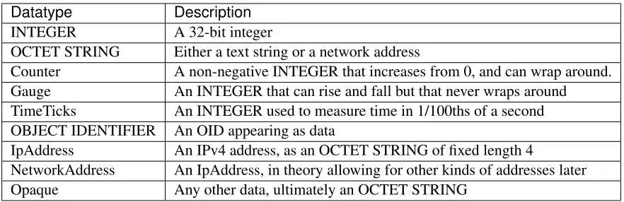
26.5 SNMPv1 Data Types . . . 618
26.6 ASN.1 Syntax and SNMP . . . 618
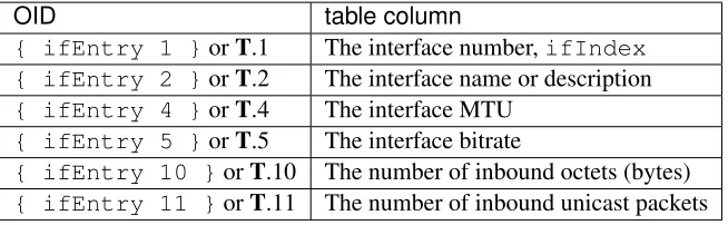
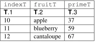
26.7 SNMP Tables . . . 619
26.8 SNMP Operations . . . 624
26.9 MIB Browsing . . . 629
26.10 MIB-2 . . . 630
26.11 SNMPv1 communities and security . . . 639
26.12 SNMP and ASN.1 Encoding . . . 640
26.13 Exercises . . . 643
27 SNMP versions 2 and 3 645 27.1 SNMPv2 . . . 645
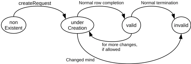
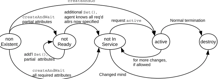
27.2 Table Row Creation . . . 656
27.3 SNMPv3 . . . 665
27.4 Exercises . . . 675
28 Security 677 28.1 Code-Execution Intrusion . . . 678
28.2 Stack Buffer Overflow . . . 679
28.3 Heap Buffer Overflow . . . 688
28.4 Network Intrusion Detection . . . 693
28.5 Cryptographic Goals . . . 694
28.6 Secure Hashes . . . 695
28.7 Shared-Key Encryption. . . 700
28.8 Diffie-Hellman-Merkle Exchange . . . 709
29 Public-Key Encryption 715
29.1 RSA. . . 715
29.2 Forward Secrecy . . . 718
29.3 Trust and the Man in the Middle . . . 718
29.4 End-to-End Encryption . . . 719
29.5 SSH and TLS . . . 720
29.6 IPsec . . . 739
29.7 DNSSEC . . . 742
29.8 RSA Key Examples . . . 751
29.9 Exercises . . . 754
30 Mininet 757 30.1 Installing Mininet. . . 758
30.2 A Simple Mininet Example . . . 760
30.3 Multiple Switches in a Line . . . 761
30.4 IP Routers in a Line . . . 764
30.5 IP Routers With Simple Distance-Vector Implementation . . . 766
30.6 TCP Competition: Reno vs Vegas . . . 769
30.7 TCP Competition: Reno vs BBR. . . 774
30.8 Linux Traffic Control (tc). . . 775
30.9 OpenFlow and the POX Controller. . . 778
30.10 Exercises . . . 790
31 Network Simulations: ns-2 793 31.1 The ns-2 simulator . . . 793
31.2 A Single TCP Sender . . . 795
31.3 Two TCP Senders Competing . . . 807
31.4 TCP Loss Events and Synchronized Losses . . . 823
31.5 TCP Reno versus TCP Vegas. . . 832
31.6 Wireless Simulation . . . 834
31.7 Epilog. . . 840
31.8 Exercises . . . 840
32 The ns-3 Network Simulator 843 32.1 Installing and Running ns-3 . . . 843
32.2 A Single TCP Sender . . . 844
32.3 Wireless. . . 853
32.4 Exercises . . . 859
23 Bibliography 861 Exercise-Numbering Conversion Tables 863 24 Selected Solutions 875 24.1 Solutions forAn Overview of Networks . . . 875
24.2 Solutions forEthernet . . . 876
24.6 Solutions forLinks . . . 878
24.7 Solutions forPackets . . . 879
24.8 Solutions forSliding Windows . . . 881
24.9 Solutions forIPv4 . . . 882
24.10 Solutions forRouting-Update Algorithms . . . 883
24.11 Solutions forLarge-Scale IP Routing. . . 883
24.12 Solutions forBorder Gateway Protocol. . . 884
24.13 Solutions forUDP . . . 884
24.14 Solutions forTCP Reno and Congestion Management . . . 885
24.15 Solutions forDynamics of TCP . . . 885
24.16 Solutions forDynamics of TCP . . . 886
24.17 Solutions forQueuing and Scheduling . . . 887
24.18 Solutions forMininet . . . 888
Indices and tables 889
Bibliography 891
Index 899
Peter L Dordal
Department of Computer Science Loyola University Chicago
Contents:
“No man but a blockhead ever wrote, except for money.” - Samuel Johnson
The textbook world is changing. On the one hand, open source software and creative-commons licensing have been great successes; on the other hand, unauthorized PDFs of popular textbooks are widely available, and it is time to consider flowing with rather than fighting the tide. Hence this open-access textbook, released for free under the Creative Commons license described below.Mene, mene, tekel pharsin.
Perhaps the last straw, for me, was patent8195571for a roundabout method to force students to purchase textbooks. (A simpler strategy might be to include the price of the book in the course.) At some point, faculty have to be advocates for their students rather than, well,Hirudinea.
This is not to say that I have anything against for-profit publishing. It is just that this particular book does not – and will not – belong to that category; the online edition will always be free. In this it is in good company: there is Wikipedia, there is a steadily increasing number of other open online textbooks out there, and there is the entire open-source world. Although the open-source-software and open-textbook models are not completely parallel, they are similar enough.
The market inefficiencies of traditional publishing are sobering: the return to authors of advanced textbooks is usually modest, while the lost-opportunity costs to users due to lack of access can be quite substantial. (None of this is meant to imply there will never be a print edition; when I started this project it seemed inconceivable that a print publisher would ever agree to having the online edition remain free, but times are changing.)
The book is updated multiple times per year (0.8 Recent Changes). This is another feature that paper publishing can’t touch.
The official book website isintronetworks.cs.luc.edu. The book is available there as online html, as a zipped archive of html files, in .pdf format, and in other formats as may prove useful.
Note that there arethreehtml variants: the original, a version using a more universally available set of uni-code characters, and a version better suited to smaller screen. In an ideal world, my Javascript would figure out which version to serve to your browser automatically; in our real world, it took me three years to get the html quick-search facility to work again after I broke it with the collapsible sidebar. See0.6 Technical considerationsbelow for more information.
0.1 Second Edition
The second edition is finally here! Mainly this involved breaking up the longer chapters, partly to make scrolling less fussy (at least on some devices), partly to restore the sense of accomplishment at finishing a chapter, and partly so the collabsible contents sidebar fits in the viewport of most devices, making sidebar scrolling unnecessary.
Division of the overlong chapters in many cases followed a logical divide: thus the IPv4 chapter became the basic IPv4 chapter and the IPv4 companion protocols, the Ethernet chapter became a chapter on basic Ethernet and a chapter on more advanced features, and the security chapter divided naturally into public-key encryption for the second half, and everything else in the first half.
In other cases, the division was less natural; the IPv6 chapters comes to mind here as the companion proto-cols Neighbor Discovery, DHCPv6 and SLAAC ended up in the same chapter as the IPv6 core protocol.
Throughout the eight-year lifetime of the first edition, I assiduously rejected renumbering any exercises; new exercises were always inserted with floating-point numbering,eg4.7. For a book that might get updated in the middle of the semester, that is essential. However, after splitting chapters and dividing the exercises appropriately, I realized that the time for renumbering was at hand. To make life easier for instructors (including me) who have assignments based on the old numbering, there is a handy conversion table here:
Exercise-Numbering Conversion Tables.
After much demand, I have finally accepted that I need to create asolutions manualfor instructors, covering at least a majority of the exercises. It is in progress; instructors should contact me if interested.
The second edition html version became available July 31, 2020.
0.2 Licensing
This text is released under the Creative Commons licenseAttribution-NonCommercial-NoDerivs. This text is like a conventional book, in other words, except that it is free. You may copy the work and distribute it to others for any noncommercial use (and for some commercial uses; see below), but all reuse requires attribution.
The Creative Commons license does not precisely spell out what constitutes “noncommercial” use. The author considers any sale of printed copies of this book, even by a non-profit organization and even if the price just covers expenses, to be commercial use. Personal printing, and free distribution of printed selections, do qualify as noncommercial.
Starting with Edition 1.9.16,commercial use is also explicitly allowed, provided thatprinted copies are not distributed. In other words, the text is also released under the terms of the Creative Commons license
Attribution-NoDerivs,amendedto include a prohibition on the distribution of printed copies. The Creative Commons license summary linked to here states that “you are free to share – copy and redistribute the material in any medium or format for any purpose, even commercially”; this license is amended by this paragraph to limit “any medium” to non-printed media. Permissible commercial uses may include, but are not limited to, use in internal training programs, use in for-profit training and educational programs, sale of the work in the electronic formats available here, and installation throughout theAmazon EC2.
The Attribution clause of the Creative Commons licenses [Section 4, (b) for by-nd or (c) for by-nc-nd] requires that redistributors of the work provide “. . . (iii) to the extent reasonably practicable, the URI, if any, that Licensor specifies to be associated with the Work”. That URI isintronetworks.cs.luc.edu.
Some of the chapters contain source code; this is licensed under theApache 2.0 license. Some code files (those which are derivative works) contain an official Apache license statement; others do not.
0.3 Classroom Use
This book is meant as a serious and more-or-less thorough text for an introductory college or graduate course in computer networks, carefully researched, with consistent notation and style, and complete with diagrams and exercises. I have also tried to rethink the explanations of many protocols and algorithms, with the goal of making them easier to understand. My intent is to create a text that covers to a reasonable extentwhythe Internet is the way it is, to avoid the endless dreary focus on TLA’s (Three-Letter Acronyms), and to remain nottoomathematical. For the last, I have avoided calculus, linear algebra, and, for that matter, quadratic terms (though some inequalities do sneak in at times). That said, the book includes a large number of back-of-the-envelope calculations – in settings as concrete as I could make them – illustrating various networking concepts.
Overall, I tried to find a happy medium between practical matters and underlying principles. My goal has been to create a book that is useful to a broad audience, including those interested in network management, in high-performance networking, in software development, or just in how the Internet is put together.
One of the best ways to gain insight into why a certain design choice was made is to look at a few alterna-tive implementations. To that end, this book includes coverage of some topics one may never encounter in practice, but which may be useful as points of comparison. These topics arguably include ATM (5.5 Asyn-chronous Transfer Mode: ATM), SCTP (18.15.2 SCTP) and even 10 Mbps Ethernet (2.1 10-Mbps Classic Ethernet).
The book can also be used as a networks supplement or companion to other resources for a variety of other courses that overlap to some greater or lesser degree with networking. At Loyola, this book has been used – sometimes coupled with a second textbook – in courses in computer security, network management, telecommunications, and even introduction-to-computing courses for non-majors. Another possibility is an alternative or nontraditional presentation of networking itself. It is when used in concert with other works, in particular, that this book’s being free is of marked advantage.
Finally, I hope the book may also be useful as a reference work. To this end, I have attempted to ensure that the indexing and cross-referencing is sufficient to support the drop-in reader. Similarly, obscure or specialized notation is kept to a minimum.
Much is sometimes made, in the world of networking textbooks, abouttop-down versus bottom-up se-quencing. This book is not really either, although the chapters are mostly numbered in bottom-up fashion. Instead, the first chapter provides a relatively complete overview of the LAN, IP and transport network layers (along with a few other things), allowing subsequent chapters to refer to all network layers without forward reference, and, more importantly, allowing the chapters to be covered in a variety of different orders. As a practical matter, when I use this text to teach Loyola’s Introduction to Computer Networks course, I cover the IP/routing and TCP material more or less in parallel.
A distinctive feature of the book is the extensive coverage of TCP: TCP dynamics, newer versions of TCP such as TCP Cubic and BBR TCP, and chapters on using the ns-2 and ns-3 simulators and the Mininet emulator. This has its roots in a longstanding goal to find better ways to present competition and congestion in the classroom. Another feature is the detailed chapter on queuing disciplines.
One thing this book makes little attempt to cover in detail is the application layer; the token example in-cluded is SNMP. While SNMP actually makes a pretty good example of a self-contained application, my recommendation to instructors who wish to cover more familiar examples is to combine this text with the appropriate application documentation.
Although the book is continuously updated, I try very hard to ensure that all editions are classroom-compatible. To this end, section renumbering is avoided to the extent practical, and, within the first edition,
existing exercises are never renumbered. This is an essential feature for a textbook that is often updated mid-semester, and a useful feature for any textbook that is updated at all. New exercises are regularly inserted, but with fractional (floating point) numbers. Existing integral exercise numbers have been given a trailing .0, to reduce confusion between exercise 12.0, say, and 12.5. I do anticipate some exercise renumbering for the second edition; as chapters there will also be divided and renumbered.
For those interested in using the book for a “traditional” networks course, I with some trepidation offer the following set of core material. In solidarity with those who prefer alternatives to a bottom-up ordering, I emphasize that this represents asetand not asequence.
• 1 An Overview of Networks
• Selected sections from2 Ethernet Basics, particularly switched Ethernet
• Selected sections from4.2 Wi-Fi
• Selected sections from7 Packets
• 8 Abstract Sliding Windows
• 9 IP version 4and/or11 IPv6
• Selected sections from13 Routing-Update Algorithms, probably including the distance-vector algo-rithm
• Selected sections from14 Large-Scale IP Routing
• 16 UDP Transport
• 17 TCP Transport Basics
• 19 TCP Reno and Congestion Management
With some care in the topic-selection details, the above can be covered in one semester along with a survey of selected important network applications, or the basics of network programming, or the introductory con-figuration of switches and routers, or coverage of additional material from this book, or some other set of additional topics. Of course, non-traditional networks courses may focus on a quite different sets of topics.
Instructors who adopt this book in a course, as either a primary or a secondary text, are strongly encouraged to let me know, as this helps support continued work on the book. Below is a list of the institutions I’m aware of so far where the book has been adopted. Commercial publishers get this information from sales records, but that won’t work here; if you want to see your institution listed, contact me!
Augustana College
Ohio University
Saint Martin’s University SUNY Delhi
University of Arkansas Community College at Batesville University of California, Santa Cruz
University of Maryland, University College University of North Alabama
University of Texas at El Paso University of the People Villanova University
Wellington Institute of Technology
0.4 Acknowledgments
I would like to thank the many Loyola students who have provided invaluable feedback on the text and the exercises. The result, I hope, is greater clarity for both. I would also like to thank the following people from outside Loyola who have contributed technical or editorial comments. I’ve included institutional affiliation if I could figure it out. If I’ve missed anyone, or their institution, please let me know.
Anonymous
Jose Alvarado University of the People Eric Freudenthal University of Texas at El Paso David Garfield
Jeff Harrang
Emmanuel Lochin Institut supérieur de l’aéronautique et de l’espace Robert Michael
Natale Patriciello Centre Tecnològic Telecomunicacions Catalunya Herman Torjussen
Alexander Wijesinha Towson University Justin Yang
Comments – from anyone – on clarity, completeness, consistency and correctness are much appreciated. Even single comments or corrections are very welcome, though I continue to seek reviewers willing to review an entire section or chapter. I can be contacted at pld AT cs.luc.edu, or via the bookcomment form.
Peter Dordal Shabbona, Illinois
0.5 Progress Notes
This work was started in the summer of 2012. Edition 1.0 was declared complete as of March 2014, and Edition 2.0 (mostly reorganization) in July 2020. The current edition is 2.0.1.
Theintronetworks.cs.luc.edu website carries the current 2.x edition (recommended), and also editions 1.0 and the final 1.9.21 edition.
0.6 Technical considerations
The book was prepared in reStructuredText using the Linux Sphinx package, which can produce multiple formats from the same source. That said, the primary format ishtml. The table-of-contents sidebar and the text sidebars work best there. Most of the diagrams were drawn using LibreOffice Draw.
The html version also provides a “Quick search” box, which, with the aid of Javascript’s
stopPropagation()method, finally coexists with the collapsible sidebar. Quick search, however, only works for all-alphabetic strings; strings with hyphens such as “wi-fi” and “Diffie-Hellman” fail. The index is an effective alternative.
The book uses a modest set of unicode special characters. Unfortunately, some of these characters are not universally available in all browsers(and I have not yet figured out how to encapsulate fonts in the html). The comma-separated characters in the first line, below, appear to have the most limited support. The math-italic Greek letters are not present in the so-called UnicodeBasic Multilingual Plane, but the symbols are, so that is not the entire explanation.
x,y,»,𝛼,𝛽,𝛾,𝜆,𝜑,𝜏,𝜚,∆,",ÝÑ,ÐÝ,ÐÑ
(,),«,𝛼,𝛽,𝛾,𝜆,𝜑,𝜏,𝜌,∆,^, Ñ,Ð ,ÐÑ
µ,?,8,ď,ě,ˆ,˜,˘,–,‰,Ñ,Ð, , , , , , , , , , ,
The characters above should look roughly as they do in the following image (the first line is the one most likely to fail):
If they do not, there are two options for browser-based viewing. If the second and third rows above display successfully, there is a unicode-saferversion of the book (both online and zipped) available at intronet-works.cs.luc.eduthat has the characters in the first row above replaced by those in the second row.
Customize fonts (button), and change at a minimum the default Sans-serif font to Symbola. Then restart Chrome.
Unfortunately, adding fonts to (non-rooted) Android devices continues to be very difficult. Worse, Android often fails to display even a box symbol “l” in the place of missing characters.
If no available browser properly displays the symbols above, I recommend the pdf format. The unicode-safer version, however,shouldwork on most systems.
At some point I hope to figure out how to handle this font situation a little better using Javascript. This turns out, however, not to be straightforward, and progress has been slow.
I could have gone with TeX and MathJax, but then I likely would have gotten rather too carried away with mathematical formulas. The character set above keeps things (relatively) simple. As of 2020 MathJax renders better than it used to, but you still cannot copy and paste.
The diagrams in the body of the text have now all been migrated to the vector-graphics .svg format, although a few diagrams rendered with line-drawing characters appear in the exercises. Most browsers now (2018) appear to support zooming in on .svg images, which is a significant step forward.
0.7 A Note On the Cover
The photo is of mahogany leaves, presumablySwietenia mahagoni. The original image was taken by Homer Edward Price and placed athttps://commons.wikimedia.org/wiki/File:Mahogany-leaves_(5606894105).gif
under a Creative Commons license; the image as used here has been cropped.
I began with the idea that the cover should depict some networking reference from the natural world. The connection between mahogany and networking comes from Bertolt Brecht’s workThe City of Mahagonny, “the city of nets”. Ok, “nets” in the sense oftrapsrather than communication, but close enough.
Alas, this turned out to be based on a misapprehension. As musicologist John Simon puts it[JS05],
Where did Brecht get the name for that lawless city that was his symbol for a capitalist society in distress? In coining the nameMahagonny, the opera’s Leokadja Begbick explains it as “the City of Nets”, i.e. traps. But the word “mahogany”, from which the name must stem, has nothing to do with nets.
It remains unclear just what“Mahagonny”did mean to Brecht.
more reading of papers and RFCs, I began to see the non-connection here as a symbol of diligent fact-checking. So there it is.
And besides, it’s green.
0.8 Recent Changes
July 31, 2020 (ver 2.0.0.0.0): start of second edition
Somewhere there might be a field of interest in which the order of presentation of topics is well agreed upon.
Computer networking is not it.
There are many interconnections in the field of networking, as in most technical fields, and it is difficult to find an order of presentation that does not involve endless “forward references” to future chapters; this is true even if – as is done here – a largely bottom-up ordering is followed. I have therefore taken here a different approach: this first chapter is a summary of the essentials – LANs, IP and TCP – across the board, and later chapters expand on the material here.
Local Area Networks, orLANs, are the “physical” networks that provide the connection between machines within, say, a home, school or corporation. LANs are, as the name says, “local”; it is theIP, or Internet Protocol, layer that provides an abstraction for connecting multiple LANs into, well, the Internet. Finally,
TCPdeals with transport and connections and actually sending user data.
This chapter also contains some important other material. The section ondatagram forwarding, central to packet-based switching and routing, is essential. This chapter also discusses packets generally, conges-tion, and sliding windows, but those topics are revisited in later chapters. Firewalls and network address translation are also covered here and not elsewhere.
1.1 Layers
These three topics – LANs, IP and TCP – are often calledlayers; they constitute the Link layer, the Internet-work layer, and the Transport layer respectively. Together with the Application layer (the software you use), these form the “four-layer model” for networks. A layer, in this context, corresponds strongly to the idea of a programming interface or library, with the understanding that a given layer communicates directly only with the two layers immediately above and below it. An application hands off a chunk of data to the TCP library, which in turn makes calls to the IP library, which in turn calls the LAN layer for actual delivery. An application doesnotinteract directly with the IP and LAN layers at all.
The LAN layer is in charge of actual delivery of packets, using LAN-layer-supplied addresses. It is often conceptually subdivided into the “physical layer” dealing with, eg, the analog electrical, optical or radio signaling mechanisms involved, and above that an abstracted “logical” LAN layer that describes all the digital – that is, non-analog – operations on packets; see 2.1.4 The LAN Layer. The physical layer is generally of direct concern only to those designing LAN hardware; the kernel software interface to the LAN corresponds to the logical LAN layer.
Application Transport
IP Logical LAN Physical LAN
This LAN physical/logical division gives us the Internetfive-layer model. This is less a formal hierarchy than anad hocclassification method. We will return to this below in1.15 IETF and OSI, where we will also introduce two more rather obscure layers that complete theseven-layer model.
1.2 Data Rate, Throughput and Bandwidth
Any one network connection –egat the LAN layer – has adata rate: the rate at which bits are transmitted. In some LANs (eg Wi-Fi) the data rate can vary with time. Throughput refers to the overall effective transmission rate, taking into account things like transmission overhead, protocol inefficiencies and perhaps even competing traffic. It is generally measured at a higher network layer than the data rate.
The termbandwidth can be used to refer to either of these, though we here use it mostly as a synonym for data rate. The term comes from radio transmission, where the width of the frequency band available is proportional, all else being equal, to the data rate that can be achieved.
In discussions about TCP, the term goodput is sometimes used to refer to what might also be called “application-layer throughput”: the amount of usable data delivered to the receiving application. Specif-ically, retransmitted data is counted only once when calculating goodput but might be counted twice under some interpretations of “throughput”.
Data rates are generally measured in kilobits per second (kbps) or megabits per second (Mbps); the use of the lower-case “b” here denotes bits. In the context of data rates, a kilobit is 103bits (not 210) and a megabit is 106 bits. Somewhat inconsistently, we follow the tradition of using kB and MB to denote datavolumes
of 210 and 220 bytes respectively, with the upper-case B denoting bytes. The newer abbreviationsKiBand
MiBwould be more precise, but the consequences of confusion are modest.
1.3 Packets
Packets are modest-sized buffers of data, transmitted as a unit through some shared set of links. Of necessity, packets need to be prefixed with aheadercontaining delivery information. In the common case known as
datagram forwarding, the header contains a destination address; headers in networks using so-called
virtual-circuit forwarding contain instead an identifier for theconnection. Almost all networking today (and for the past 50 years) is packet-based, although we will later look briefly at some “circuit-switched” options for voice telephony.
Single and multiple headers data
data header
At the LAN layer, packets can be viewed as the imposition of a buffer (and addressing) structure on top of low-level serial lines; additional layers then impose additional structure. Informally, packets are often referred to asframesat the LAN layer, and assegmentsat the Transport layer.
The maximum packet size supported by a given LAN (eg Ethernet, Token Ring or ATM) is an intrinsic attribute of that LAN. Ethernet allows a maximum of 1500 bytes of data. By comparison, TCP/IP packets originally often held only 512 bytes of data, while early Token Ring packets could contain up to 4 kB of data. While there are proponents of very large packet sizes, larger even than 64 kB, at the other extreme the ATM (Asynchronous Transfer Mode) protocol uses 48 bytes of data per packet, and there are good reasons for believing in modest packet sizes.
One potential issue is how to forward packets from a large-packet LAN to (or through) a small-packet LAN; in later chapters we will look at how the IP (or Internet Protocol) layer addresses this.
Generally each layer adds its own header. Ethernet headers are typically 14 bytes, IP headers 20 bytes, and TCP headers 20 bytes. If a TCP connection sends 512 bytes of data per packet, then the headers amount to 10% of the total, a not-unreasonable overhead. For one common Voice-over-IP option, packets contain 160 bytes of data and 54 bytes of headers, making the header about 25% of the total. Compressing the 160 bytes of audio, however, may bring the data portion down to 20 bytes, meaning that the headers are now 73% of the total; see25.11.4 RTP and VoIP.
In datagram-forwarding networks the appropriate header will contain the address of the destination and perhaps other delivery information. Internal nodes of the network calledroutersorswitcheswill then try to ensure that the packet is delivered to the requested destination.
The concept of packets and packet switching was first introduced by Paul Baran in 1962 ([PB62]). Baran’s primary concern was with network survivability in the event of node failure; existing centrally switched protocols were vulnerable to central failure. In 1964, Donald Davies independently developed many of the same concepts; it was Davies who coined the term “packet”.
It is perhaps worth noting that packets are buffers built of 8-bitbytes, and all hardware today agrees what a byte is (hardware agrees by convention on the order in which the bits of a byte are to be transmitted). 8-bit bytes are universal now, but it was not always so. Perhaps the last great non-byte-oriented hardware platform, which did indeed overlap with the Internet era broadly construed, was the DEC-10, which had a 36-bit word size; a word could hold five 7-bit ASCII characters. The early Internet specifications introduced the termoctet(an 8-bit byte) and required that packets be sequences of octets; non-octet-oriented hosts had to be able to convert. Thus was chaos averted. Note that there are still byte-oriented data issues; as one example, binary integers can be represented as a sequence of bytes in eitherbig-endianorlittle-endianbyte order (16.1.5 Binary Data).RFC 1700specifies that Internet protocols use big-endian byte order, therefore sometimes called network byte order.
1.4 Datagram Forwarding
In the datagram-forwarding model of packet delivery, packet headers contain a destination address. It is up to the intervening switches or routers to look at this address and get the packet to the correct destination.
In datagram forwarding this is achieved by providing each switch with a forwarding table of
xdestination,next_hopypairs. When a packet arrives, the switch looks up the destination address (presumed globally unique) in its forwarding table and finds thenext_hopinformation: the immediate-neighbor ad-dress to which – or interface by which – the packet should be forwarded in order to bring it one step closer
to its final destination. The next_hop value in a forwarding table is a single entry; each switch is responsible for only one step in the packet’s path. However, if all is well, the network of switches will be able to deliver the packet, one hop at a time, to its ultimate destination.
The “destination” entries in the forwarding table do not have to correspond exactly with the packet des-tination addresses, though in the examples here they do, and they do for Ethernet datagram forwarding. However, for IP routing, the table “destination” entries will correspond to prefixes of IP addresses; this leads to a huge savings in space. The fundamental requirement is that the switch can perform a lookup operation, using its forwarding table and the destination address in the arriving packet, to determine the next hop.
Just how the forwarding table is built is a question for later; we will return to this for Ethernet switches in
2.4.1 Ethernet Learning Algorithmand for IP routers in13 Routing-Update Algorithms. For now, the forwarding tables may be thought of as created through initial configuration.
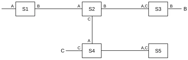
In the diagram below, switch S1 has interfaces 0, 1 and 2, and S2 has interfaces 0,1,2,3. If A is to send a packet to B, S1 must have a forwarding-table entry indicating that destination B is reached via its interface 2, and S2 must have an entry forwarding the packet out on interface 3.
S1 0 S2
1
2 3 0
1
2
A B
C D
E Two switches S1 and S2,
with interface numbers shown
A complete forwarding table for S1, using interface numbers in thenext_hopcolumn, would be:
S1
destination next_hop
A 0
C 1
B 2
D 2
E 2
The table for S2 might be as follows, where we have consolidated destinations A and C for visual simplicity.
S2
destination next_hop
A,C 0
D 1
E 2
In the network diagrammed above, all links are point-to-point, and so each interface corresponds to the unique immediate neighbor reached by that interface. We can thus replace the interface entries in the
next_hopcolumn with the name of the correspondingneighbor. For human readers, using neighbors in thenext_hopcolumn is usually much more readable. S1’s table can now be written as follows (with consolidation of the entries for B, D and E):
S1
destination next_hop
A A
C C
B,D,E S2
A central feature of datagram forwarding is that each packet is forwarded “in isolation”; the switches in-volved do not have any awareness of any higher-layer logical connections established between endpoints. This is also calledstateless forwarding, in that the forwarding tables have no per-connection state. RFC 1122put it this way (in the context of IP-layer datagram forwarding):
To improve robustness of the communication system, gateways are designed to be stateless, forwarding each IP datagram independently of other datagrams. As a result, redundant paths can be exploited to provide robust service in spite of failures of intervening gateways and networks.
The fundamental alternative to datagram forwarding is virtual circuits,5.4 Virtual Circuits. In virtual-circuit networks, each router maintains state about each connection passing through it; different connections can be routed differently. If packet forwarding depends, for example, on per-connection information –eg
both TCP port numbers – it is not datagram forwarding. (That said, it arguably stillisdatagram forwarding if web traffic – to TCP port 80 – is forwarded differently than all other traffic, because that rule does not depend on the specific connection.)
Datagram forwarding is sometimes allowed to use other information beyond the destination address. In theory, IP routing can be done based on the destination address and somequality-of-serviceinformation, allowing, for example, different routing to the same destination for high-bandwidth bulk traffic and for low-latency real-time traffic. In practice, most Internet Service Providers (ISPs) ignore user-provided quality-of-service information in the IP header, except by prearranged agreement, and route only based on the destination.
By convention, switching devices acting at the LAN layer and forwarding packets based on the LAN address are calledswitches(or, originally, bridges; some still prefer that term), while such devices acting at the IP layer and forwarding on the IP address are calledrouters. Datagram forwarding is used both by Ethernet switches and by IP routers, though the destinations in Ethernet forwarding tables are individual nodes while the destinations in IP routers are entirenetworks(that is, sets of nodes).
In IP routers within end-user sites it is common for a forwarding table to include a catchalldefaultentry, matching any IP address that is nonlocal and so needs to be routed out into the Internet at large. Unlike the consolidated entries for B, D and E in the table above for S1, which likely would have to be implemented as actual separate entries, a default entry is a single record representing where to forward the packet if no other destination match is found. Here is a forwarding table for S1, above, with a default entry replacing the last three entries:
S1
destination next_hop
A 0
C 1
default 2
Default entries make sense only when we can tell by looking at an address that it does not represent a nearby node. This is common in IP networks because an IP address encodes the destination network, and routers generally know all the local networks. It is however rare in Ethernets, because there is generally no correlation between Ethernet addresses and locality. If S1 above were an Ethernet switch, and it had some means of knowing that interfaces 0 and 1 connected directly to individual hosts, not switches – and S1 knew the addresses of these hosts – then making interface 2 a default route would make sense. In practice, however, Ethernet switches do not know what kind of device connects to a given interface.
1.5 Topology
In the network diagrammed in the previous section, there are no loops; graph theorists might describe this by saying the network graph isacyclic, or is atree. In a loop-free network there is a unique path between any pair of nodes. The forwarding-table algorithm has only to make sure that every destination appears in the forwarding tables; the issue of choosing between alternative paths does not arise.
However, if there are no loops then there is noredundancy: any broken link will result in partitioning the network into two pieces that cannot communicate. All else being equal (which it is not, but never mind for now), redundancy is a good thing. However, once we start including redundancy, we have to make decisions among the multiple paths to a destination. Consider, for a moment, the following network:
S1 S2
S3 S4 B
A
Should S1 list S2 or S3 as the next_hop to B? Both paths A S1 S2 S4 B and A S1 S3 S4 B get there. There is no right answer. Even if one path is “faster” than the other, taking the slower path is not exactly wrong (especially if the slower path is, say, less expensive). Some sort of protocol must exist to provide a mechanism by which S1 can make the choice (though this mechanism might be as simple as choosing to route via the first path discovered to the given destination). We also want protocols to make sure that, if S1 reaches B via S2 and the S2 S4 link fails, then S1 will switch over to the still-working S1 S3 S4 B route.
1.5.1 Traffic Engineering
In some cases the decision above between routes A S1 S2 S4 B and A S1 S3 S4 B might be of material significance – perhaps the S2–S4 link is slower than the others, or is more congested. We will use the term
traffic engineeringto refer to any intentional selection of one route over another, or any elevation of the priority of one class of traffic. The route selection can either be directly intentional, through configuration, or can be implicit in the selection or tuning of algorithms that then make these route-selection choices auto-matically. As an example of the latter, the algorithms of13.1 Distance-Vector Routing-Update Algorithm
build forwarding tables on their own, but those tables are greatly influenced by the administrative assignment of link costs.
With pure datagram forwarding, used at either the LAN or the IP layer, the path taken by a packet is deter-mined solely by its destination, and traffic engineering is limited to the choices made between alternative paths. We have already, however, suggested that datagram forwarding can be extended to take quality-of-service information into account; this may be used to have voice traffic – with its relatively low bandwidth but intolerance for delay – take an entirely different path than bulk file transfers. Alternatively, the network manager may simply assign voice traffic a higher priority, so it does not have to wait in queues behind file-transfer traffic.
The quality-of-service information may be set by the end-user, in which case an ISP may wish to recognize it only for designated users, which in turn means that the ISP will implicitly use the traffic source when making routing decisions. Alternatively, the quality-of-service information may be set by the ISP itself, based on its best guess as to the application; this means that the ISP may be using packet size, port num-ber (1.12 Transport) and other contents as part of the routing decision. For some explicit mechanisms supporting this kind of routing, see13.6 Routing on Other Attributes.
At the LAN layer, traffic-engineering mechanisms are historically limited, though see3.4 Software-Defined Networking. At the IP layer, more strategies are available; see25 Quality of Service.
1.6 Routing Loops
A potential drawback to datagram forwarding is the possibility of arouting loop: a set of entries in the forwarding tables that cause some packets to circulate endlessly. For example, in the previous picture we would have a routing loop if, for (nonexistent) destination C, S1 forwarded to S2, S2 forwarded to S4, S4 forwarded to S3, and S3 forwarded to S1. A packet sent to C would not only not be delivered, but in circling endlessly it might easily consume a large majority of the bandwidth. Routing loops typically arise because the creation of the forwarding tables is often “distributed”, and there is no global authority to detect inconsistencies. Even when there is such an authority, temporary routing loops can be created due to notification delays.
Routing loops can also occur in networks where the underlying link topology is loop-free; for example, in the previous diagram we could, again for destination C, have S1 forward to S2 and S2 forward back to S1. We will refer to such a case as alinearrouting loop.
All datagram-forwarding protocols need some way of detecting and avoiding routing loops. Ethernet, for example, avoids nonlinear routing loops by disallowing loops in the underlying network topology, and avoids linear routing loops by not having switches forward a packet back out the interface by which it arrived. IP provides for a one-byte “Time to Live” (TTL) field in the IP header; it is set by the sender and decremented
by 1 at each router; a packet is discarded if its TTL reaches 0. This limits the number of times a wayward packet can be forwarded to the initial TTL value, typically 64.
In datagram routing, a switch is responsible only for the next hop to the ultimate destination; if a switch has a complete path in mind, there is no guarantee that the next_hop switch or any other downstream switch will continue to forward along that path. Misunderstandings can potentially lead to routing loops. Consider this network:
B
A
D
C B
E
D might feel that the best path to B is D–E–C–B (perhaps because it believes the A–D link is to be avoided). If E similarly decides the best path to B is E–D–A–B, and if D and E both choose their next_hop for B based on these best paths, then a linear routing loop is formed: D routes to B via E and E routes to B via D. Although each of D and E have identified a usablepath, that path is not in fact followed. Moral: successful datagram routing requires cooperation and a consistent view of the network.
1.7 Congestion
Switches introduce the possibility of congestion: packets arriving faster than they can be sent out. This can happen with just two interfaces, if the inbound interface has a higher bandwidth than the outbound interface; another common source of congestion is traffic arriving on multiple inputs and all destined for the same output.
Whatever the reason, if packets are arriving for a given outbound interface faster than they can be sent, a queue will form for that interface. Once that queue is full, packets will bedropped. The most common strategy (though not the only one) is to drop any packets that arrive when the queue is full.
The term “congestion” may refer either to the point where the queue is just beginning to build up, or to the point where the queue is full and packets are lost. In their paper[CJ89], Chiu and Jain refer to the first point as theknee; this is where the slope of the load vs throughput graph flattens. They refer to the second point as thecliff; this is where packet losses may lead to a precipitous decline in throughput. Other authors use the termcontentionfor knee-congestion.
In the Internet, most packet losses are due to congestion. This is not because congestion is especially bad (though it can be, at times), but rather that other types of losses (egdue to packet corruption) are insignificant by comparison.
When to Upgrade?
external or in-house. Monitoring of links and routers for congestion can, however, help determine exactly whatpartsof the network would most benefit from upgrade.
We emphasize that the presence of congestion doesnotmean that a network has a shortage of bandwidth. Bulk-traffic senders (though not real-time senders) attempt to send as fast as possible, and congestion is simply the network’sfeedbackthat the maximum transmission rate has been reached. For further discussion, including alternative definitions of longer-term congestion, see[BCL09].
Congestionisa sign of a problem in real-time networks, which we will consider in25 Quality of Service. In these networks losses due to congestion must generally be kept to an absolute minimum; one way to achieve this is to limit the acceptance of new connections unless sufficient resources are available.
1.8 Packets Again
Perhaps the core justification for packets, Baran’s concerns about node failure notwithstanding, is that the same link can carry, at different times, different packets representing traffic to different destinations and from different senders. Thus, packets are the key to supportingshared transmission lines; that is, they support themultiplexing of multiple communications channels over a single cable. The alternative of a separate physical line between every pair of machines grows prohibitively complex very quickly (though virtual circuitsbetween every pair of machines in a datacenter are not uncommon; see5.4 Virtual Circuits). From this shared-medium perspective, an important packet feature is the maximum packet size, as this repre-sents the maximum time a sender can send before other senders get a chance. The alternative of unbounded packet sizes would lead to prolonged network unavailability for everyone else if someone downloaded a large file in a single 1 Gigabit packet. Another drawback to large packets is that, if the packet is corrupted, the entire packet must be retransmitted; see7.3.1 Error Rates and Packet Size.
When a router or switch receives a packet, it (generally) reads in the entire packet before looking at the header to decide to what next node to forward it. This is known as store-and-forward, and introduces a forwarding delay equal to the time needed to read in the entire packet. For individual packets this forwarding delay is hard to avoid (though some switches do implement cut-through switching to begin forwarding a packet before it has fully arrived), but if one is sending a long train of packets then by keeping multiple packetsen routeat the same time one can essentially eliminate the significance of the forwarding delay; see7.3 Packet Size.
Total packet delay from sender to receiver is the sum of the following:
• Bandwidth delay,iesending 1000 Bytes at 20 Bytes/millisecond will take 50 ms. This is a per-link delay.
• Propagation delaydue to the speed of light. For example, if you start sending a packet right now on a 5000-km cable across the US with a propagation speed of 200 m/µsec (= 200 km/ms, about 2/3 the speed of light in vacuum), the first bit will not arrive at the destination until 25 ms later. The bandwidth delay then determines how much after that the entire packet will take to arrive.
• Store-and-forward delay, equal to the sum of the bandwidth delays out of each router along the path • Queuing delay, or waiting in line at busy routers. At bad moments this can exceed 1 sec, though that is rare. Generally it is less than 10 ms and often is less than 1 ms. Queuing delay is the only delay component amenable to reduction through careful engineering.
See7.1 Packet Delayfor more details.
1.9 LANs and Ethernet
Alocal-area network, or LAN, is a system consisting of • physical links that are, ultimately, serial lines
• common interfacing hardware connecting the hosts to the links
• protocols to make everything work together
We will explicitly assume that every LAN node is able to communicate with every other LAN node. Some-times this will require the cooperation of intermediate nodes acting as switches.
Far and away the most common type of (wired) LAN is Ethernet, originally described in a 1976 paper by Metcalfe and Boggs[MB76]. Ethernet’s popularity is due to low cost more than anything else, though the primary reason Ethernet cost is low is that high demand has led to manufacturing economies of scale.
The original Ethernet had a bandwidth of 10 Mbps (megabits per second; we will use lower-case “b” for bits and upper-case “B” for bytes), though nowadays most Ethernet operates at 100 Mbps and gigabit (1000 Mbps) Ethernet (and faster) is widely used in server rooms. (By comparison, as of this writing (2015) the data transfer rate to a typical faster hard disk is about 1000 Mbps.) Wireless (“Wi-Fi”) LANs are gaining popularity, and in many settings have supplanted wired Ethernet to end-users.
Many early Ethernet installations were unswitched; each host simply tapped in to one long primary cable that wound through the building (or floor). In principle, two stations could then transmit at the same time, rendering the data unintelligible; this was called acollision. Ethernet has several design features intended to minimize the bandwidth wasted on collisions: stations, before transmitting, check to be sure the line is idle, they monitor the linewhiletransmitting to detect collisions during the transmission, and, if a collision is detected, they execute a random backoff strategy to avoid an immediate recollision. See2.1.5 The Slot Time and Collisions. While Ethernet collisions definitely reduce throughput, in the larger view they should perhaps be thought of as a part of a remarkably inexpensive shared-access mediation protocol.
In unswitched Ethernets every packet is received by every host and it is up to the network card in each host to determine if the arriving packet is addressed to that host. It is almost always possible to configure the card to forwardallarriving packets to the attached host; this poses a security threat and “password sniffers” that surreptitiously collected passwords via such eavesdropping used to be common.
Password Sniffing
In the fall of 1994 at Loyola University I remotely changed the root password on several CS-department unix machines at the other end of campus, using telnet. I told no one. Within two hours, someone else logged into one of these machines, using the new password, from a host in Europe. Password sniffing was the likely culprit.
Due to both privacy and efficiency concerns, almost all Ethernets today are fully switched; this ensures that each packet is delivered only to the host to which it is addressed. One advantage of switching is that it effectively eliminates most Ethernet collisions; while in principle it replaces them with aqueuingissue, in practice Ethernet switch queues so seldom fill up that they are almost invisible even to network managers (unlike IP router queues). Switching also prevents host-based eavesdropping, though arguably a better solution to this problem is encryption. Perhaps the more significant tradeoff with switches, historically, was that Once Upon A Time they were expensive and unreliable; tapping directly into a common cable was dirt cheap.
Ethernet addresses are six bytes long. Each Ethernet card (ornetwork interface) is assigned a (supposedly) unique address at the time of manufacture; this address is burned into the card’s ROM and is called the card’s
physicaladdress orhardwareaddress orMAC(Media Access Control) address. The first three bytes of the physical address have been assigned to the manufacturer; the subsequent three bytes are a serial number assigned by that manufacturer.
By comparison, IP addresses are assigned administratively by the local site. The basic advantage of having addresses in hardware is that hosts automatically know their own addresses on startup; no manual configura-tion or server query is necessary. It is not unusual for a site to have a large number of identically configured workstations, for which all network differences derive ultimately from each workstation’s unique Ethernet address.
The network interface continually monitors all arriving packets; if it sees any packet containing a destination address that matches its own physical address, it grabs the packet and forwards it to the attached CPU (via a CPU interrupt).
Ethernet also has a designatedbroadcast address. A host sending to the broadcast address has its packet received by every other host on the network; if a switch receives a broadcast packet on one port, it forwards the packet out every other port. This broadcast mechanism allows host A to contact host B when A does not yet know B’s physical address; typical broadcast queries have forms such as “Will the designated server please answer” or (from the ARP protocol) “will the host with the given IP address please tell me your physical address”.
Traffic addressed to a particular host – that is, not broadcast – is said to beunicast.
Because Ethernet addresses are assigned by the hardware, knowing an address does not provide any direct indication of where that address is located on the network. In switched Ethernet, the switches must thus have a forwarding-table record for each individual Ethernet address on the network; for extremely large networks this ultimately becomes unwieldy. Consider the analogous situation with postal addresses: Ethernet is somewhat like attempting to deliver mail using social-security numbers as addresses, where each postal worker is provided with a large catalog listing each person’s SSN together with their physical location. Real postal mail is, of course, addressed “hierarchically” using ever-more-precise specifiers: state, city, zipcode, street address, and name / room#. Ethernet, in other words, does not scale well to “large” sizes.
Switched Ethernet works quite well, however, for networks with up to 10,000-100,000 nodes. Forwarding tables with size in that range are straightforward to manage.
To forward packets correctly, switches must know where all active destination addresses in the LAN are located; traditional Ethernet switches do this by a passivelearningalgorithm. (IP routers, by comparison, use “active” protocols, and some newer Ethernet switches take the approach of 3.4 Software-Defined Networking.) Typically a host physical address is entered into a switch’s forwarding table when a packet from that host is firstreceived; the switch notes the packet’s arrival interface andsourceaddress and assumes that the same interface is to be used to deliver packets back to that sender. If a given destination address has
not yet been seen, and thus is not in the forwarding table, Ethernet switches still have the backup delivery option offlooding: forwarding the packet to everyone by treating the destination address like the broadcast address, and allowing the host Ethernet cards to sort it out. Since this broadcast-like process is not generally used for more than one packet (after that, the switches will have learned the correct forwarding-table entries), the risks of excessive traffic and of eavesdropping are minimal.
Thexhost,interfaceyforwarding table is often easier to think of asxhost,next_hopy, where the next_hop node is whatever switch or host is at the immediate other end of the link connecting to the given interface. In a fully switched network where each link connects only two interfaces, the two perspectives are equivalent.
1.10 IP - Internet Protocol
To solve the scaling problem with Ethernet, and to allow support for other types of LANs and point-to-point links as well, the Internet Protocolwas developed. Perhaps the central issue in the design of IP was to support universal connectivity (everyone can connect to everyone else) in such a way as to allow scaling to enormous size (in 2013 there appear to be around ~109 nodes, although IP should work to 1010 nodes or more), without resulting in unmanageably large forwarding tables (currently the largest tables have about 300,000 entries.)
In the early days, IP networks were considered to be “internetworks” of basic networks (LANs); nowadays users generally ignore LANs and think of the Internet as one large (virtual) network.
To support universal connectivity, IP provides a global mechanism for addressing and routing, so that packets can actually be delivered from any host to any other host. IP addresses (for the most-common version 4, which we denoteIPv4) are 4 bytes (32 bits), and are part of theIP headerthat generally follows the Ethernet header. The Ethernet header only stays with a packet for one hop; the IP header stays with the packet for its entire journey across the Internet.
An essential feature of IPv4 (and IPv6) addresses is that they can be divided into anetworkpart (a prefix) and ahostpart (the remainder). The “legacy” mechanism for designating the IPv4 network and host address portions was to make the division according to the first few bits:
first few bits first byte network bits host bits name application
0 0-127 8 24 class A a few very large networks 10 128-191 16 16 class B institution-sized networks 110 192-223 24 8 class C sized for smaller entities
For example, the original IP address allocation for Loyola University Chicago was 147.126.0.0, a class B. In binary, 147 is10010011.
IP addresses, unlike Ethernet addresses, areadministratively assigned. Once upon a time, you would get your Class B network prefix from the Internet Assigned Numbers Authority, orIANA (they now delegate this task), and then you would in turn assign the host portion in a way that was appropriate for your local site. As a result of this administrative assignment, an IP address usually serves not just as anendpoint identifier
The Class A/B/C definition above was spelled out in 1981 inRFC 791, which introduced IP. Class D was added in 1986 by RFC 988; class D addresses must begin with the bits 1110. These addresses are for
multicast, that is, sending an IP packet to every member of a set of recipients (ideally without actually transmitting it more than once on any one link).
Nowadays the division into the network and host bits is dynamic, and can be made at different positions in the address at different levels of the network. For example, a small organization might receive a /27 address block (1/8 the size of a class-C /24) from its ISP, eg200.1.130.96/27. The ISP routes to the or-ganization based on this /27 prefix. At some higher level, however, routing might be based on the prefix 200.1.128/18; this might, for example, represent an address block assigned to the ISP (note that the first 18 bits of 200.1.130.x match 200.1.128; the first two bits of 128 and 130, taken as 8-bit quantities, are “10”). The network/host division point is not carried within the IP header; routers negotiate this division point when they negotiate the next_hop forwarding information. We will return to this in9.5 The Classless IP Delivery Algorithm.
The network portion of an IP address is sometimes called thenetwork number or network addressor
network prefix. As we shall see below, most forwarding decisions are made using only the network prefix. The network prefix is commonly denoted by setting the host bits to zero and ending the resultant address with a slash followed by the number of network bits in the address: eg12.0.0.0/8 or 147.126.0.0/16. Note that 12.0.0.0/8 and 12.0.0.0/9 represent different things; in the latter, the second byte of any host address extending the network address is constrained to begin with a 0-bit. An anonymous block of IP addresses might be referred to only by the slash and following digit,eg“we need a /22 block to accommodate all our customers”.
All hosts with the same network address (same network bits) are said to be on the sameIP networkand
must be located together on the same LAN; as we shall see below, if two hosts share the same network address then they will assume they can reach each other directly via the underlying LAN, and if they cannot then connectivity fails. A consequence of this rule is that outside of the siteonly the network bits need to be looked at to route a packet to the site.
Usually, all hosts (or more precisely all network interfaces) on the same physical LAN share the same network prefix and thus are part of the same IP network. Occasionally, however, one LAN is divided into multiple IP networks.
Each individual LAN technology has a maximum packet size it supports; for example, Ethernet has a maximum packet size of about 1500 bytes but the once-competing Token Ring had a maximum of 4 kB. Today the world has largely standardized on Ethernet and almost entirely standardized on Ethernet packet-size limits, but this was not the case when IP was introduced and there was real concern that two hosts on separate large-packet networks might try to exchange packets too large for some small-packet intermediate network to carry.
Therefore, in addition to routing and addressing, the decision was made that IP must also support fragmen-tation: the division of large packets into multiple smaller ones (in other contexts this may also be called
segmentation). The IP approach is not very efficient, and IP hosts go to considerable lengths to avoid frag-mentation. IP does require that packets of up to 576 bytes be supported, and so a common legacy strategy was for a host to limit a packet to at most 512 user-data bytes whenever the packet was to be sent via a router; packets addressed to another host on the same LAN could of course use a larger packet size. Despite its limited use, however, fragmentation is essential conceptually, in order for IP to be able to support large packets without knowing anything about the intervening networks.
IP is abest effortsystem; there are no IP-layer acknowledgments or retransmissions. We ship the packet