Published online July 10, 2014 (http://www.sciencepublishinggroup.com/j/ijepe) doi: 10.11648/j.ijepe.20140303.16
ISSN: 2326-957X (Print); ISSN: 2326-960X (Online)
A new scheme based on correlation technique for
generator stator fault detection-part π
R. Abd Allah
1, S. M. Mohamed
2, E. H. Shehab-Eldin
2, M. E. Masoud
21
Buraydah Colleges, Faculty of Engineering, Electrical Power Department, Qassim Region, Kingdom of Saudi Arabia
2
Helwan University, Faculty of engineering, Department of Electrical Machines& Power Engineering, Cairo, Egypt
Email address:
[email protected] (R. Abd Allah), [email protected] (S. M. Mohamed), [email protected] (E. H. Shehab-Eldin)
To cite this article:
R. Abd Allah, S. M. Mohamed, E. H. Shehab-Eldin, M. E. Masoud. A New Scheme Based on Correlation Technique for Generator Stator Fault Detection-Part π. International Journal of Energy and Power Engineering. Vol. 3, No. 3, 2014, pp. 147-153.
doi: 10.11648/j.ijepe.20140303.16
Abstract:
An experimental model for the synchronous generator was implemented and windings tapped at different positions to obtain faults at different locations on the stator windings. LABVIEW was used to obtain an interface between the experimental model and the suggested digital relay; whereas the proposed algorithm is executed using MATLAB. The obtained experimental results showed a great similarity with those obtained from ATP-EMTP simulation and that indicated the capability of safe application of the new auto/cross correlation protection technique.Keywords:
Power System, Generator Protection, Fault Classification, Correlation Coefficient, Internal Faults, ATP-EMTP1. Introduction
Faults associated with synchronous generators may be classified as either insulation failures or abnormal running conditions [1-2]. An insulation failure in the stator winding will result in an inter-turn fault, a phase fault or a ground fault, but most commonly the latter since most insulation failures eventually bring the winding into direct contact with the core. Differential relays, in particular the digital ones, are used to detect stator faults of generators [3-5].
The proposed technique of digital relay for synchronous generators protection using statistical auto/cross correlation coefficients [6] was described in part І of this paper. The technique evaluation using the simulation results show that, the proposed technique is able to provide correct response rapidly for a wide range of different fault conditions. In this paper, the experimental part is presented including the following items:
Building up the laboratory model for the proposed digital relay using data acquisition card and all accessories.
Preparing a synchronous generator with stator windings tapping to execute different types of internal and inter-turn faults.
Interface between the used generator and proposed digital relay.
Obtain test results for internal and external faults. Verify the performance of proposed digital relay under various fault conditions.
2. Laboratory Model Description
The laboratory model consists of the following main parts:
(a) Synchronous generator under test.
(b) Three phase induction motor (as prime mover). (c) Three phase load.
(d) Transducers (Current transformers). (e) Data acquisition card.
(f) Digital relay (Computer, PC).
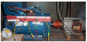
The main parts of the laboratory model used in testing the proposed technique for synchronous generator protection are shown in Fig. 1. It consists of the synchronous generator, prime mover induction motor and the used load; their data are listed in Appendix A.
2.1. Synchronous Generator Winding Taps
The synchronous generator under test is the source of AC power and electrical energy for loads. The stator windings of the synchronous generator are modified by the authors in order to obtain different taps to facilitate examining internal and inter-turn faults at different positions. Table 1 shows the obtained winding taps and the associated voltage. This will enable us to examine various types of internal and inter-turn faults along the stator windings. Fig. 2 shows the stator winding taps of synchronous generator under test.
Figure 2. Stator Winding Taps of Synchronous Generator under Test.
Table 1. Stator winding taps and the associated voltage.
Terminal block number
Number of turns
% Winding for each phase
Phase voltage (A-N) (Volt)
1 168 100 220
2 84 50 110
3 72 42.86 94.28
4 60 35.71 78.57
5 48 28.57 62.86
6 36 21.42 47.14
7 24 14.28 31.43
8 12 7.14 15.71
9 0 0 0
2.2. Three Phase Induction Motor (As a Prime Mover)
The three phase induction motor is functioning as a prime mover for providing the mechanical energy to synchronous generator. The induction motor data is listed in Appendix A.
2.3. Three Phase Load
The generator load is three phase variable resistances and inductive; their data are given in Appendix A.
2.4. Current Transformer
Two side currents of stator winding for synchronous generator are used as the input signals to the proposed differential relay; these currents are obtained through two current transducers per each phase. The current transducer convert the current signal to low voltage signal suitable for
the input channel of the data acquisition card which operates with input voltage signals within ±10 V. the transformation ratio of the current transducer is 1A/100 mV where the CT burden is 0.1 Ohm. The data of used current transformers are given in Appendix A.
2.5. Data Acquisition Card (Ni Usb-6008/6009 Device)
The data acquisition card (DAC) is used to convert the analog data into a suitable that can be used via a digital processor. The National Instruments USB-6008/6009 is data acquisition device; it provides connection to eight analog input (AI) channels, two analog output (AO) channels, 12 digital input/output (DIO) channels, and a 32-bit counter with a Full-Speed USB interface. The Data acquisition card is characterized by 14-bit input resolution, 8 input channels single ended or 4 input channels differential and the sampling rate is 48 kHz. The DAC is adjusted to operate in differential mode. Two input channels for two side’s currents per phase are used with a sampling frequency of 1 kHz for each channel.
2.6. Digital Relay
PC computer is used to virtually simulate the intelligent electronic device (IED) relay. The computer in this case is functioning as digital relay. The specification of this computer is HP Pavilion Entertainment PC, processor: 2.1 GHZ and installed memory (RAM): 3.00 GB.
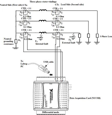
Figure 3 shows wiring from CTs burden of phase ‘’A’‘ to two input channels of NI USB-6008/6009 device to operate in differential mode.
Figure 3. Laboratory Model Main Parts of the Protection System.
3. Basic Principle
developed and theoretically examined in part І of this paper. For convenience the suggested protection algorithm is based on auto/cross-correlation theory. The technique measures the currents at the both ends of stator windings and uses the calculated auto/cross-correlation coefficients for the two-side currents of each phase, for making relay trip or no trip decision. The suggested protection algorithm
can give good results without filter because it uses a number of samples per each correlated window. The proposed algorithm used a correlated window of one cycle in these tests.
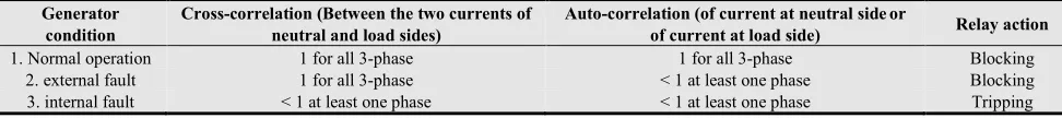
Tripping action of the algorithm relies on the conditions given in Table 2.
Table 2. Auto/cross-correlation coefficient ranges at different fault conditions.
Generator condition
Cross-correlation (Between the two currents of neutral and load sides)
Auto-correlation (of current at neutral sideor
of current at load side) Relay action
1. Normal operation 1 for all 3-phase 1 for all 3-phase Blocking
2. external fault 1 for all 3-phase < 1 at least one phase Blocking
3. internal fault < 1 at least one phase < 1 at least one phase Tripping
Testing the performance of the proposed algorithm for phase ‘’A’‘ stator winding protection, at different types of faults internally and externally, is described in the next section.
4. Experimental Relay Performance
Testing of the proposed technique based on the auto/cross-correlation coefficients for generator protection (see part І of this paper) was completed for various cases. All results shown in this section are done under the operating conditions listed in Table 3.
Table 3. Operating conditions for practical model.
Electrical component (operating condition) Data
generator Load impedance generator load current
220 + j 0.0 Ohm 1 amp
Operating phase voltage (RMS) of generator 220 Volt
Generator grounding impedance 0.0 ohm
4.1. Case 1: Normal Operation at Generator Load Current = 1 Amp
As expected in normal operation condition, no trip signal is initiated due to cross-correlation between the two current signals of neutral and load sides, auto-correlation of current signal at neutral sideand auto-correlation of current signal at load side are fixed and approximately one. This is illustrated in Figs. 4 (a-e).
(a) Generator Neutral and Load Currents for Phase A.
(b) Auto-correlation for Neutral Current.
(c) Cross-correlation between Neutral
(d) Auto-correlation for Load Current.and Load Currents.
(e) No Trip Action for Case 1.
Figures 4 (a-e). Test Results for Case 1 (Normal Operation).
4.2. Case 2: External SLG (C-N) Fault Through
Resistance (Rf ) = 10 Ohm
Figures present the phase ‘’A’‘ generator current signals at the two neutral and load end sides, and their auto/cross-correlation coefficients. In this case, it is noticed that the phase ‘’A’‘ primary currents for neutral and load sides during the fault are identical and higher than the pre-fault currents as shown in Fig. 5(a). The calculated cross-correlation coefficients are equal and close to unity before and during fault occurrence as presented in Fig. 5(b). The algorithm calculates cross-correlation coefficient between each two corresponding windows (each window is one cycle) for two current signals at the neutral and load end sides. The calculated auto-correlation coefficients are fixed, equal and close to unity before fault occurrence, and they decrease with fault occurrence (see Figs. 5 (c-d)). The algorithm calculates auto-correlation coefficient between each two successive windows shifted from each other by one cycle (each window is one cycle) for current signals at the neutral and load end sides. Auto-correlation coefficients is estimated for differentiation between external fault and normal operation, their values are closely to unity for neutral and load current signals in case of normal operation and they are less than one in case of external faults as shown in this case.
A trip flag depends on the cross-correlation values, if their values are less than unity then a trip signal is sent for isolation generator CB. But this case is external fault condition and no tripping signal is issued as shown in Fig. 5(e).
(a) Generator Neutral and Load Currents
(b) Cross-correlation between Neutral
(c) Auto-correlation for Neutral Current for Phase A.
(d) Auto-correlation for Load Current. and Load Currents.
(e) No Trip Action for Case 2.
Figures 5(a-e). Test Results for Case 2.
4.3. Case 3: External DL (A-C) Fault Through Resistance
(Rf ) = 2.5 Ohm
As expected in case of external DL (A-C) fault through resistance (Rf ) = 2.5 ohm, no trip signal is initiated due to
cross-correlation coefficient between the two current signal of neutral and load sides are fixed and approximately one. Auto-correlation coefficients of current signals at neutral sideand at load side are less than one with fault occurrence. This is illustrated in the presented Figs. 6 (a-e).
(a) Generator Neutral and Load Currents for Phase A.
(c) Cross-correlation between Neutral
(d) Auto-correlation for Load Current. and Load Currents.
(e) No Trip Action for Case 3.
Figures 6(a-e). Test Results for Case 3.
Many test results of internal fault conditions at various fault types and resistances are obtained, trip signal is initiated with fault start due to cross-correlation coefficient between the two current signals of neutral and load sides are less than one. Also, Auto-correlation coefficients of current signals at neutral sideand at load side are less than one with fault occurrence. This is illustrated in the following different cases of internal faults conditions.
4.4. Case 4: Internal SLG (A-N) Fault Through
Resistance (Rf ) = 2.5 Ohm at 100% on Stator
Winding
(a) Generator Neutral and Load Currents for Phase A.
(b) Auto correlation for Neutral Current.
(c) Cross-correlation between Neutral
(d) Auto-correlation for Load Current. and Load Currents.
(e) Trip Action for Case 4.
Figures 7(a-e). Test Results for Case 4.
4.5. Case 5: Internal DLG (A-B-N) Fault Through
Resistance (Rf ) = 2.5 Ohm at 100% on Stator
Winding
(b) Auto-correlation for Neutral Current.
(c) Cross-correlation between Neutral
(d) Auto-correlation for Load Current. and Load Currents.
(e) Trip Action for Case 5.
Figures 8(a-e). Test Results for Case 5.
4.6. Case 6: Inter-Turn Fault Through Resistance (Rf ) =
0 Ohm Between Taps7.14%- 14.28% On Stator Winding
(a) Generator Neutral and Load Currents for Phase A.
(b) Cross-correlation between Neutral and Load Currents.
(c) Trip Action for Case 6.
Figures 9(a-e). Test Results for Case 6.
From the obtained results, it is clear that the proposed technique for differential protection algorithm of phase ‘’A’‘ succeeded in differentiating between external and internal faults occurring on the generator stator besides identifying faulted phase(s) and detecting inter-turn faults in the same phase of stator winding. Thus a reliable and efficient technique has been presented for detecting generator stator winding internal and external faults by using both auto-correlation and cross-correlation functions.
5. Conclusion
Appendix A. Electrical data of the main parts for the laboratory model.
Electrical parameter Data
Synchronous Generator:
Type STC-5 (KAIJ IELI GROUP,
CHINA) star connected
Rated active power 5 kWatt
Nominal voltage 380 V
Rated current 9.5 Amp
Frequency 50 Hz
Rated speed 1500 r/min
Power factor Cos (ϕ) = 0.8
Excitation voltage 82 Volt
Excitation current 3.6 Amp
Number of poles 4 poles/phase.
Number of turns per phase 168
Number of slots per phase 12 slot/phase
Neutral grounding resistance (Rn) 0.0 ohm
Prime Mover (3-phase induction motor):
Type Y100L2-4 (MADE IN CHINA)
Rated active power 3k Watt (4HP)
Nominal voltage 380 V.
Rated current 6.8 Amp
Frequency 50 Hz
Rated speed 1430 r/min (47.67 Hz)
Generator Load: (a) Restive Load
Type Three phase Variable resistances
Rload 220-29.33 ohm
Iload 1-7.5 Amp
(b) Inductive Load
Type Three phase Variable Inductances
XLoad 1-4 kVAR
Current Transformer (CT):
Type MSQ-40
CTR 2/1
Rated burden 5 VA
Class 1
References
[1] "Protective Relays Applications Guide," The English Electric Company Limited, Relay Division, Stafford, 1975. [2] Mozina C. J., IEEE Tutorial on the Protection of
Synchronous Generators, IEEE Tutorial Course, IEEE Power Engineering Society Special Publ., no. 95 TP102, 1995.
[3] Megahed A. I., Student Member, IEEE, and O. P. Malik, Fellow, IEEE, "An Artificial neural network based digital differential scheme for synchronous generator stator winding protection," IEEE Transactions on Power Delivery, vol 14, 1999.
[4] A. I. Taalab, H.A. Darwish and T. A. Kawady, “ANN-Based Novel Fault Detector For Generator Windings Protection,” IEEE Transaction on Power Delivery, Vol. 14, No 3, pp. 824 -830, 1999.
[5] N.W.Kinhekar, Sangeeta Daingade and Ajayshree Kinhekar, “Current Differential Protection of Alternator Stator Winding,” Paper submitted to the International Conference on Power Systems Transients (IPST2009) in Kyoto, Japan, 2009.