Filling Analysis of Spiral Fluidity Standard
using ProCast Simulation
Manoj Kayat
#1, Vaibhav Jain
#2, Jitendra Patil
#3,Fatema Qureshi
#4#1 Research Scholar, IPE Department, Shri. G.S. Institute of Technology & Science, Indore, MP, India #2, 3 ,4 Assistant Professor, IPE Department, Shri. G.S. Institute of Technology & Science, Indore, MP, India
SGSITS, 23 Park Road, Indore, MP, India, 452003
Abstract — Casting simulation is a virtual process which ensures casting without defects. It involves computer-aided modelling, pattern design, simulation and optimization. Casting simulation is a proven technique for all major cast metals and processes. Results are reliable for complex castings. Fluidity of molten metal plays an important role in producing sound complex castings. The objective of the present analysis study is to identify the factors affecting casting fluidity by changing sprue height, pouring temperature, and flow rate on the fluidity of aluminium alloy (AlSi_13). On the basis of casting variable of sprue height, effect on filling and solidification vary on spiral.
Keywords — Casting, mould filling and solidification, Fluidity, and Simulation.
I. INTRODUCTION
The Industries from foundry are continuously facing new challenges to attain high performance materials, high quality products and economic in costs. Now a days with emerging technologies in Computer simulation is gaining importance in foundry industries in optimization of processes, control system and product quality (Sabitino et, al. 2004). Light weight components are in demand for advanced aerospace and automobile industries. The thin and intricate casting of alluminum alloy are extensively used for producing durable and light weight components. Fluidity is one of the critical parameter limits the predictability and quality of casted components. (Sabito and Arneberg). Fluidity is a property and can be defined as ability to flow through the given cavity, (Dewhrist, It is qualitative in term of the solidification length of a standard spiral casting (Ravi, 2005). Fluidity depends upon many factors categorized as follow:
Metallurgical variables:
Chemical Composition of Molten Metal
Solidification range molten metal
Viscosity Heat of fusion
Mould and mould/metal variables:
Heat transfer coefficient
Mould and metal thermal
conductivity
Mould and metal mass density Specific heat
Surface tension
Casting Variables:
Metal head
Channel diameter
Casting temperature (Superheat) Oxide/particle content
Fluidity can be controlled and optimized by testing and analysing combinations of various factors nd variables.
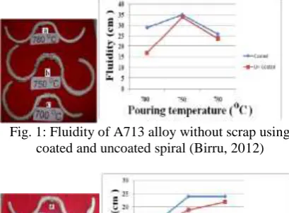
Birru et. al, in 2011 investigated for the influence of pouring temperatures on the fluidity of aluminium alloy range such as: A206, A518 and A713 alloys. The spiral tests of these alloys were conducted for temperatures at 680O C, 715O C, and 780O C. when the pouring temperature is raised from 680O C to 715O C, the constant increment in fluidity length was found to be ranging from 12.3 cm to 14.3 cm. When the pouring temperature ranged from 715O C to 780O C, enormous increment in fluidity length ranging from 14.3 cm to 45 cm was observed for A206 alloys. The study revealed that increase in temperature increases fluidity length.
Fig. 1: Fluidity of A713 alloy without scrap using coated and uncoated spiral (Birru, 2012)
Fig. 2: Fluidity of A713 alloy with 25 per cent scrap addition using coated and uncoated spiral (Birru,
2012)
Kayal et. al, 2011 had studied the effect of SiCp on fluidity of the LM6/SiCp metal matrix composites. The study revealed that on increasing the weight percentage of SiC particles in matrix metal, the spiral length decreases in comparison to the matrix metal. Fluidity of Aluminium alloy and its composites in thin walled castings increases along with pouring temperature.
Zang et. al, 2009 had investigated the fluidity evolution of an Al-10% B4C experimental composite during long holding periods has been investigated by using a vacuum fluidity test. The study reveal that fluidity of Al–10% B4C decreases with the increase of the holding time, and during the first period of holding time (up to 400 min), the deterioration of fluidity is faster than the rest. It was found that the fluidity of the composite melt decreased with the increase of the holding time.
II. SIMULATIONSETUP
In the experiment AlSi_13 (Aluminium-Silicon alloy) was taken as a casting material and Green sand was used as a moulding material.
Fig. 3: Simulation Process of FEM Solver ProCast
MATERIAL PROPERTIES
Green sand were used for preparing mould cavity. It is a mixture of sand, clay, water and some organic additives e.g. sea coal. The sand are used for many
reasons including: easily available, elimination of metal penetration, reduction of burn-on, prevention of mound erosion, improved surface finish, and improved casting quality, reduction of scrap, and decreased cleaning costs. Table.1 shows the composition of Green sand and Table.2 shows AlSi_13 materials composition. All compositions in Wt %.
Table 1: Green sand composition.
Element Wt%
Silica sand 96% (up to)
Clay 2 to 5%
Water 2 to 8%
Binder <0.002
Parting sand <0.001
Table 2: Composition of material
Element Wt%
Si 13
Table 3: Thermo-physical properties of Al-Si and Green sand
Properties Molten
metal (Al-Si)
Mould (Sand)
Density (Kg/m3) 2600 1.37 X 10³
Viscosity (Pa.s) 1.698 -
Conductivity (W/m/K)
3.55 X 101 5.90 X 10⁻¹
Specific heat(KJ/Kg/K)
1.02 1.03
Latent heat (KJ/Kg)
522 -
Liquidus temperature (oC)
572 -
Solidus temperature (oC)
570 -
III. SIMULATIONMETHODUSINGFEM
SOLVERPROCAST
Fig.5: Import Part and mould box (PARASOLID file format) into MeshCast. (It is a portion of Pro CAST).
Fig.6: Assign boundary condition
Fig.7: Filling simulation of the spiral.
IV.EFFECTOFVARIATIONOFSPRUE
HEIGHTONFILLINGAND
SOLIDIFICATION
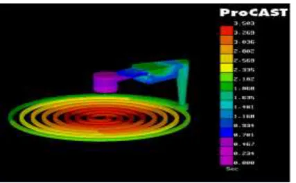
With the help of simulation, experiment is performed to obtain the filling time through different sprue height in the spiral. In the following simulation 150 mm, 200 mm, and 250 mm sprue height were used separately to fill the molten metal in mould cavity of spiral cast part of 10 mm thickness. Filling time has been shown in the following figures:
Filling effect at sprue height:
Fig.8: Filling time analysis for Sprue height of 150mm
Fig.9: Filling time analysis for Sprue height of 200 mm
Fig.10: Filling time analysis for Sprue height at 250 mm.
Filling simulation result shown in table:
Table 4: Casting filling variation at different sprue height
Sprue height (mm)
Casting filling time (s)
%Variation
(Reference to 150 Sprue height)
150 3.503 0
200 3.581 2.22
Location of thermocouple:
Fig.11: Location of thermocouple
V. RESULTS
Time – Temperature graph for sprue height
Using simulation, temperature behaviour of spiral is studied at each quadrant of round of spiral and taking average of the temperature at each quadrants of spiral round like as R1, R2, R3, R4, R5, R6, and R7.
Fig.12: Time- Temperature plot for sprue height (h = 150mm)
Fig.13: Time-Temperature plot for Sprue height (h = 200mm)
Fig.14: Time-Temperature plot for Sprue height (h = 250mm)
Here results concludes that, the percentage variation in casting filling time varies from 0 to 2.2 to 4.28 with changing sprue height from 150 to 200 to 250 mm respectively.
VI.CONCLUSION
Casting solidification simulation is useful for predicting fluidity length of cast part for its standard development.
Simulation of filling and solidification using FEM based solver, ProCAST
FEM based solver ProCAST gives closer result to actual shop floor result for filling and solidification. By using FEM solver, results may be found out for not only filling and solidification parameters but also for whole area inside casting. It gives results approximately near to the experimental work performed.
Analysing method design using FEM based solver, Pro CAST
It is required to have sufficient knowledge of Foundry and other thermo-mechanical properties, for performing method design in FEM based solver, ProCAST. It predicts better results obtained for estimation of fluidity length with standard form based upon the casting parameters’ like temperature, velocity, flow rate & sprue head.
Interpretations of simulation results
ProCAST gives results related to fluidity length of solidification of the casting part however it takes more time. It shows the result once the solution run is completed. It also gives more accurate result in comparison to VEM based solver AutoCAST.
VII. REFERENCES
1. Arnberg Lars (2008), “Castablity – Fluidity and Hot Tearing”, ASM Hand Book, Vol.15, pp. 375-378. 2. Birru, A.K., Karunakar, D. B., Mahapatram, M. M. (2012),
“Fluidity of A713 Cast Alloy with and without Scrap Addition using Double Spiral Fluidity Test: A Comparison”, World Academy of Science, Engineering and Technology 61 (2012).
4. Dewhirst, B., Li S., Hogan P. And Apelian D. (2008), “Castablity Measure for Die Casting Alloys: Fluidity, Hot Tearing and Die Soldering”, International Conference High Tech Die-casting, Montichiari.
5. Kayal, S., Behera, R. and Sutradhar, G. (2011), “Effect of SiCp on Fluidity of the LM6/SiCp Metal Matrix Composites”, International Journal of Emerging trends in Engineering and Development, Vol. 3, pp. 2249-6149. 6. Kermanpur, A., Mohmoudi, Sh. And Hajipur, A. (2007),
“Numerical Simulation of Metal Flow and Solidification in the Multi Cavity Moulds of Automotive Components”, Journal of Material Processing Technology 206, pp. 62-68. 7. Ravi, B. (2008), “Casting Simulation and Optimisation
Benefits, Bottlenecks, and Best Practices”, Indian Foundry Journal, pp. 1-12.
8. Ravi, B. (2012), “Casting Solidification Feed-Path Computation and Industrial Application”, Transaction of Indian Institute Metallurgy 65 pp. 521–525.
9. Sabatino, M. and Arnberg, L. (2004), “A review on the fluidity of Al based alloys”, Metallurgical Science and Technology, Vol. 22 No.1.
10. Sabatino, M., Arnberg, L. and Bonollo, F. (2005), “Simulation of fluidity in Al-Si alloys”, Metallurgical Science and Technology, Vol. 23 No. 1.