Design & Structural Analysis of Hydraulic
and Ferro Fluid Twin Tube Shock Absorber
for Two Wheeler
R. Narendra Kumar
1, Ch. Mani Kumar
2, P.Surendra
31,2Asst. Professor & Department of Mechanical Engineering & Sasi Institute of Technology & Engineering, Tadepalligudem, India
3Assoc. Professor & Department of Mechanical Engineering & Sasi Institute of Technology & Engineering, Tadepalligudem, India
Abstract- Stress and strain analysis is very important to predicting and preventing failures in materials when those are exposed to load. This paper aims to model and simulate the stresses and strain analysis of a hydraulic and ferro fluid twin tube shock absorber application of 356 kg designed. Modelling and analysis were performed by using modelling software and analysis software i.e. Solid Work 2014, ANSYS and HYPERMESH10. Initially a 3D modal of shock absorber was created by SolidWorks and meshing is carried out by hypermesh software. Stress and frequencies of both the twin tube shock absorbers were determined by Ansys. The obtained values are compared with analytical values.
Keywords— Shock Absorber, Hydraulic fluid, Ferro fluid, Solid Works, HYPERMESH, FEA.
Introduction
Shock absorbers are very important in automobiles. The shock absorbers absorb maximum loads and provide cushioning effects to passengers and cargos. The amount of cushioning is depends up on the type of the fluids used in shock absorbers. Generally two types of shock absorbers are used one is mono tube shock absorber and second one is twin tube shock absorber. This study attempted to analyse the frequency and stress on hydraulic and ferro fluid shock absorber by using HYPERMESH and FEA analysis. The simulation data is very important because of this information is useful for further design improvements. Stress analysis is very important for to determine fatigue and life of the component. Vibration analysis also very use full for determine frequency, critical damping, under damping, over damping and resonance.
Pinjarla. Poornamohan et.al. (2012)They concluded that spring steel for spring is best and also their modified
design was safe. The obtained stress and displacement values were less for modified design[1].
S.Gopinath et.al. (2014) They developed a “magnetic shock absorber” which helps to know how to achieve low cost and minimize the size[2].
Rahul Tekade et.al (2015) They compared the obtained results for both materials and identified the natural frequency is more for ASTM A228 than 67SiCr5.Finally the concluded and suggested as per their analysis using ASTMA228 [high carbon spring wire] for spring is best[3].
G.R. Chavhan et.al (2014) They are analysed the shock absorber by using fem analysis and used three different materials . The concluded the Carbon Fibre has the greater shock absorbing properties but disadvantage is that it was break earlier than Spring Steel and Beryllium Copper[4].
Ammar A.Aldair and et.al , (2011) in their study they reduced the energy consumption resulting for driving the actuators in active suspension, the electromagnetic device has been introduced which is capable of converting most of the vehicle’s vibration energy into electrical energy through the rotation of the device and store them in the battery and used to generate appropriate damping forces to improve the riding comfort & road handling[5].
M.D. Rao. Et.al. (2002) They used electrodynamics shakers to obtain the equivalent dynamic properties of shock absorbers for NVH applications. Finally, they concluded some shakers were capable of withstanding static pre-loads which suitable for testing shock absorbers under larger displacements and lower frequencies[6].
Pradeep Khande, et al. have done an optimization analysis and experimental results of a retrofit regenerative shock absorber for vibration energy harvesting from vehicle suspension. A prototype four phase linear generator was developed and characterized the theoretical and experimental values. Finally his research work is possible to harvest energy from vehicles vibration in a bumpy roads and increases the load carrying capacity.
II. Design Considerations Spring:
Mean diameter of coil, (D) = 33.3mm Diameter of wire, (d) = 6.7mm Total no. of coils, (n) = 6 Height (h)= 99.90mm
Outer diameter of spring coil, DO = D+d= 40mm
Let, weight of the bike= 131kg Weight of the three persons = 225kg Total weight of the bike & persons = 356kg Consider dynamic loads (w) = 435kg = 4267.35 N Single shock absorber weight (W) = w/2 = 217.5kg = 2133.67N
Compression spring (δ) = WD3n/G.d4 Spring index (C) = D/d = 5
Therefore δ = 42.6 mm Spring rate (K)= W/ δ = 50.08 Pitch of the coil, (P) = (Lf-Ls/n1)+ d
The buckling factor for the hinged end and built in end spring
Wcr = qx KLxLf = 50.08 x 0.1 x 99.99 = 500.74 N
Shock Absorber:
Length of the axial rod = 70mm Diameter of the plate = 45mm Thickness of the plate = 3mm Diameter of top end = 8mm Diameter of bottom end = 8mm Diameter of the cylinder = 27mm Length of the tube =76.93mm
II.2.3D Model
Fig.1. Coil Spring
Fig.2.Tube
Fig.3. Axial Rod
II.3. 2D Model
Fig.5. Front& Side view of an axial rod
Fig.6. Top & Front view of an cylinder
III. Methodology
The main objective of the study is to analyse the shock obsoebers with using different fluids. Both the obtained values were compared with analytical values.
Fig.7. Process flow chart for shock absorber
III.1. Modelling
The 3-D modelling was done by using SolidWorks software.
Fig.8. 3-D model shock absorber
III.2. Meshing
All the components was meshed by using HYPERMESH software
Fig.9.Meshing(Hypermesh) model shock absorber
III.3. FEM analysis
The maximum load for both hydraulic and ferro fluid shock absorbers during applications 356kg
III.4. Material and fluids Steel
Ferro fluid
Density 1.07 g/cm3
Viscosity 0.27pascal
Shear strength 100kpa-1100kpa
Hydraulic fliuid
Density 0.8 g/ml
Poissionsratio 0.5
III.5. Boundary Conditions
Fig.10. Boundary Conditions
The boundary conditions ware considered at upper and bottom end of the both the shock absorber
III.6. Loading
The force has been acting on shock absorber, with condersing the fluid and without condersing the fluid
IV. Results and Discussions
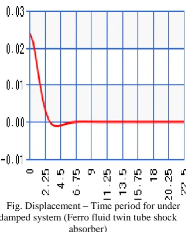
Fig.27& 33 shows the displacement and frequency distribution on hydraulic and ferro fluid twin tube shock absorber meshing modal. It can be seen that the maximum frequency and displacement of hydraulic fluid values were 19.178 Hz and 4.453m. The maximum frequency and displacement of ferro fluid values were 0.53 Hz and 0.024m.The stiffness of the hydraulic twin tube twin tube shock absorber (783.91 N/m) was much greater than the ferro fluid twin tube shock absorber (775.31N/m).In model analysis observed the damping rations of hydraulic and ferro fluid twin tube shock absorbers were 0.51 and 0.52. These two shock absorbers were belongs
to under damped systems because of the damping ratio below the ԑ = 1. Fig. 26 & 18 shows the stress distribution on hydraulic and ferro fluid twin tube model shock absorber. It can be seen that the maximum Von Misses stress of hydraulic and ferro fluid twin tube shock absorbers were 30.299 and 36.904 KN/m2.The analytical calculations was calculated by following equations. The obtained analytical values were compared with model analysis values. The theoretical vibration of both the shock absorbers ware provided in the Table 1. The experimental model analysis of both the shock absorbers were provided in the Table 2.The static analysis of both the shock absorbers were provided in reaming tables.
Undamped free vibration:
Stiffness of the spring, K= (Gxd4)/(8xnxD3) = ((55x10e3) x (6.7)4/(8x6x(33.3)3) = 62.3 N-m
Circular frequency of the motion (ῳn) =
=
= 1.31 rad/sec • Restoring force = W-k(δ+x)
• The frequency of vibration, fn = 1/2π
Hz = 1/2π = 0.02 Hz
• The mass is displaced from its equilibrium position by a distance x = A cosῳnt + B sinῳnt
x1 = (1) cos(1.31x1.22) + (13.33) sin(1.31x1.22)
= 1.37mm
x2 = (1) cos(1.31x2.30) + (13.33)
sin(1.31x2.30) = 1.56mm
x3 = (1) cos(1.31x3.42) + (13.33)
sin(1.31x3.42)= 2mm Where A = xo and B = vo/ ῳn
Energy method :
Kinetic energy, T = ½ m ẋ2
T1 = ½ (356)(17.49)2 = 54450.21kg-m/sec
T2 = ½(356)(17.36)2
= 53643.78 kg-m/sec
T3 = ½(356)(17.30)2 = 53273.62 kg-m/sec
Potential energy, V = ½ k ẋ2 V1= ½(62.3)(1.37)2
= 58.46 N(or)kgm/sec2
V2 = ½(62.3)(1.56)2 =75.80 N(or)kgm/sec2
V3 = ½(62.3)(2) 2
=124.6N(or)kgm/sec2
Rayleigh’s method:
Maximum velocity at mean position ,
ẋ = ῳnA = (1.31)x(1)
=1.31m/sec
Maximum kinetic energy at mean position = ½ m ῳn2A2= ½ (356)(1.31)2(1)2= 305 kg m2/sec2
Maximum potential energy at extreme position = ½k A2= ½(62.3)(1)2= 31.15 kg m2/sec2
Hydraulic fluid:
Energy dissipation in viscous damping ∆E= πcῳX2 Amplitude X = 4F/k = (4x356x9.81)/(89.36)= 0.15632 m
Modulus of rigidity (G) 55x103 N/mm2 Young’s modulus (EX) 1.965x10⁵ N/mm2 Poisson’s ratio (PRXY) 0.25
Therefore, energy dissipation in viscous damping ∆E= πcῳX2
∆E = π (5.736)(200π)(0.15632) 2= 275.54 N-m Power, P =∆E/60 KW = 275.54/60 = 4.59 KW Damping ratio, ԑ = C/Cc
Where, C = Damping coefficient Cc = Critical damping
Damping coefficient C = Force/Velocity = (356 x 9.81)/(0.02x1000)= 174.68 NS/m
Critical damping Cc = 2 = 2( )
= 297 NS/m
Therefore Damping ratio, ԑ = C/Cc =174.68/297
= 0.58 Therefore, this is the under frequency.
Damped frequency, ῳd = ῳ
= 1.067 rad/sec
Time period of the motion td = 2 π/ ῳd = 2 π/1.067 =
5.85 sec
Ferro fluid:
Energy dissipation in viscous damping ∆E= πcῳX2 = 276.67 N-m
Damping ratio, ԑ = C/Cc
Where, C = Damping coefficient Cc = Critical damping
Damping coefficient ( C )= Force/Velocity = 0.4818 NS/m
Critical damping (Cc) = 2 =3.6957 NS/m
Therefore Damping ratio (ԑ) = C/Cc = 0.13
Therefore, this is the under frequency.
Damped frequency (ῳd) = ῳ = 1.29
rad/sec
Time period of the motion (td) = 2 π/ ῳd = 4.87 s
Static Analysis for ferro fluid twin tube shock absorber and weight 356kg using spring steel as a material Displacement Directi on Maxi. Stress (MPa) Mini. Stress (MPa) Deformation (m) X 0.834e-4 -0.122e-3 0.004504 Y 0.542e-7 -0.004503 0.004504 Z 0.320e-3 -0.121e-3 0.004504
Stress Directi on Maxi. Stress (MPa) Mini. Stress (MPa) Deformation (m) 14.462 -80.169 0.004504 Y 17.741 -80.428 0.004504 Z 13.348 -81.975 0.004504
Strain Directi on Maxi. Stress (MPa) Mini. Stress (MPa) Deformation (m) Y 0.001154 2397e-8 0.004504
Vonmisses stress Maxi. Stress (MPa) Mini. Stress (MPa) Deformation (m) 36.904 0.408e-3 0.004504
Fig.11. Static Load applied on tetra meshed model
Fig.12. Displacement (u) in x- direction
Fig.14. Displacement (u) in z- direction
Fig.15.Stress (s) in x- direction
Fig.16.Stress (s) in y- direction
Fig.17. Stress (s) in z- direction
Fig.18. Vonmisses stresses
Static Analysis for hydraulic fluid twin tube shock absorber and weight 356kg using spring steel as a material
Displacement
Direction Maxi. Stress (MPa)
Mini. Stress (MPa)
Deformation (m) X 0.834e-4 -0.111e-3 0.004455 Y 0.541e-7 -0.004454 0.004455 Z 0.319e-3 -0.12e-3 0.004455
Stress
Direction Maxi. Stress (MPa)
Mini. Stress (MPa)
Deformation (m) X 14.462 -80.169 0.004455 Y 17.741 -80.428 0.004455 Z 13.349 -81.974 0.004455
Strain
Direction Maxi. Stress (MPa)
Mini. Stress (MPa)
Deformation (m) Y 0.001154 2397e-8 0.004455
Vonmisses Stress
Maxi. Stress (MPa)
Mini. Stress (MPa)
Fig.19. Stress(s) in x- direction
Fig.20. Stress(s) in y- direction
Fig.21. Stress(s) in z- direction
Fig.22. Displacement(u) in x- direction
Fig.23. Displacement(u) in y- direction
Fig.25.Strain(e) in y- direction
Fig.26 Vonmisses stress
Model analysis for hydraulic and ferro twin tube shock absorber and load 356 kg using spring steel as a material
Hydraulic Fluid
Fig.27. Model 1
Fig.28. Model 2
Fig.29. Model 3
Fig.31. Model 5
Fig.32. Model 1
Fig.33. Model 2
Fig.34. Model 3
Fig.35. Model 5
Fig. Displacement – Time period for under damped system (Hydraulic fluid twin tube shock absorber)
Fig. Displacement – Time period for under damped system (Ferro fluid twin tube shock
absorber)
Table.1. Theoretical variational analysis for hydraulic and ferro fluid twin tube shock
absorber Calculations:
S.
No
.
Type
of
shock
absor
ber
Lo
ad
(k
g)
Stifne
ss
(N/m
m)
Velocity
(m/s)
Freque
ncy
(Hz)
Damp
ing
ratio
Dampin
g
frequen
cy(Hz)
Time
period
(sec)
Displa
cement
(mm)
Energ
y
Dissip
ation
(N-m)
Amplit
ude(m)
1
Ferro
fluid
twin
tube
shock
absorb
er
35
6
62.3
0.02
0.20
0.58
1.067
5.85
1.64
276.6
7
0.1563
2
2
Hydra
ulic
fluid
twin
tube
shock
absorb
er
35
6
62.3
0.02
0.20
0.13
1.29
4.87
1.64
275.5
4
0.1563
2
Table.2. Model analysis for hydraulic and ferro fluid twin tube shock absorber
S.No.
Hydraulic fluid twin tube shock absorber
Ferro fluid twin tube shock absorber
1
Displacement(m)
Frequency(Hz)
Displacement(m)
Frequency(Hz)
2
3.77
9.678
0.024088
0.36153
3
3.492
10.335
0.023824
0.368364
4
3.586
10.761
0.002483
0.433725
5
4.453
11.517
0.600e
-40.494246
Table.3. Variational analysis for hydraulic and ferro fluid twin tube shock absorber
S.No Type of fluid
Material
Load
(N)
Stiffness
(N/m)
Damped
frequency
(rad/sec
)
Time
Period
(S)
Damping
Ratio
1
Ferro Fluid
Steel
3492.36 775.3
1.118
5.62
0.52
2
Hydraulic
Fluid
3492.36 783.91
1.121
5.60
0.51
Conclusion
In this paper designed a hydraulic and ferro fluid twin tube shock absorber. The 3D model of shock absorber was designed by using SolidWorks software.The model meshing was done by using HYPERMESH 10 software. The FEA was done by Ansys. The modal analysis was successfully carried out to determine displacement and frequencies on a hydraulic and ferro fluid twin tube shock absorber. The structural analysis was also successfully carried out to determine maximum stress and deflection on a hydraulic and ferro fluid twin tube shock absorber. Both the shock absorbers took material as a steel.
Compared theoretical model values with experimental model analysis values of shock absorbers.
In this study found out at a 356 kg load the frequency of the ferro fluid shock absorber is less as compared to the hydraulic fluid shock absorber.
Finally the conclusion is ferro fluid shock absorber is best compare to hydraulic fluid shock absorber.
This study found out that there is a analytical (2-D) and numerical (3-D) results. The future study will include experimental investigation.
References
[1] Pinjarla.Poornamohan1 , Lakshmana Kishore, “DESIGN AND ANALYSIS OF A SHOCK ABSORBER” International Journal of Research in
Engineering and Technology ISSN: 2319-1163 Volume: 01 Issue: 04 | Dec-2012
[2] S.Gopinath 1*, R.J. Golden Renjith 2, J.Dineshkumar3 “Design and fabrication of magnetic shock absorber”, International Journal of Engineering & Technology (2014) 208-211
[3] Rahul Tekade1, Chinmay Patil2, “Structural and Modal
Analysis of Shock Absorber of Vehicle” International Journal of Engineering Trends and Technology (IJETT) – Volume 21 Number 4 – March 2015 ISSN: 2231-5381
[4] G.R. Chavhan1*, S.W. Burande2 , Dr.L.P.Dhole3
“ ANALYSIS OF SHOCK ABSORBER USING DIFFERENT MATERIAL OF SPRING” International Journal of Advanced Engineering Technology Int J Adv Engg Tech/Vol. V/Issue IV/Oct.-Dec.,2014/19-21
[5] Ammar A. Aldair and Weiji J. Wang “Neural Controller Based Full Vehicle Nonlinear Active Suspension Systems with Hydraulic Actuators” International Journal of Control and Automation Vol. 4 No. 2, June, 2011
[6] M.D. Rao, S. Gruenberg, (2002) “Measurement of Equivalent Stiffness and Damping of Shock Absorbers”, Experimental Techniques, Vol.26, No.2, pp.39-42.
[7] A.Simms and D.Crolla (2002), “The influence of damper properties on vehicle dynamic behaviour,” SAE Technical Paper Series, 2002-01-0319.