Polymorphic DWT Based on Lifting Method
for Dynamic Image Compression
M. Nagabushanam1, Dr P Kumar21
Department of Electronics and Communication Engineering, MSRIT, Bangalore. India
2
Department of ECE, KSR College of Engineering, Tiruchengode. India *Corresponding author: M. Nagabushanam
Discrete wavelet transform (𝐷𝑊𝑇) is increasingly being used for advanced image and video processing, and computer graphics. 𝐷𝑊𝑇forms a significant part of the computations in the image/video compression algorithms and many image compression schemes based on 𝐷𝑊𝑇 architecture are reported. Several hardware architectures reported in the literature fail to address the requirements of applications having a dynamic aspect. In this article, a Polymorphic Wavelet (𝑝𝑜𝑙𝑦 − 𝐷𝑊𝑇) architecture is presented with dynamic hardware allocation and hardware reusability features. A filter switching architecture based on the lifting technique is presented for dynamically shifting between the 𝐿𝑒 − 𝐺𝑎𝑙𝑙’𝑠 5/3 and𝐷𝑎𝑢𝑏𝑒𝑐𝑖𝑒𝑠 9/7 filters. A single design addresses the 5/3 as well as 9/ 7 filter implementation. Furthermore the design achieves a multiplier free implementation with a high clock frequency.
Keywords: DWT, poly-DWT, dynamic hardware allocation, lifting, Le-Gall, Daubechies, 5/3, 9/7, coefficients.
I. Introduction
Development of scalable encoders and reconfigurable hardware has enabled multimedia services over the embedded devices [1] [6] [25].Multimedia data is bulky and to minimize the size of data encoders and compression techniques are used. Discrete wavelet transform (𝐷𝑊𝑇) is increasingly being used for advanced image and video processing, and computer graphics [17].
𝐷𝑊𝑇forms a significant part of the computations in the image/video compression algorithms and many image compression schemes based on 𝐷𝑊𝑇 architecture are reported in literature [6] [15] [16] [18]. Reference [16] introduced the sub-band coding for high-compression using Embedded Zero-tree Wavelet (𝐸𝑍𝑊) structures while [15] presented a more efficient 𝐷𝑊𝑇 based encoding to improve Shapiro’s 𝐸𝑍𝑊 coding. Image and video compression have openly incorporated
𝐷𝑊𝑇 in recent researches on motion [14], 3-D and 4-D sub band coding [7], [20]. 4-Due to its features of higher compression ratio and scalability, 𝐷𝑊𝑇 is increasingly becoming popular in compression application for audio and video. Research work carried out for compression and decompression using the 𝐷𝑊𝑇 filters proved to be beneficial for multimedia applications. Based on the research findings the 𝐷𝑊𝑇 filters are also incorporated in the 𝐽𝑃𝐸𝐺 standard [14] [24] [25]. The 𝐽𝑃𝐸𝐺2000 standard adopts the biorthogonal 𝐿𝑒 − 𝐺𝑎𝑙𝑙 5/3 wavelet for lossless compression and the
𝐷𝑎𝑢𝑏𝑒𝑐𝑖𝑒𝑠 9/7 wavelet for lossy compression. There are two main approaches of implementing 𝐷𝑊𝑇 the traditional convolutional based implementation [13] and the lifting based implementation [10] [3]. Research work presented in [3] [4] [5] [10] and [11] prove that the lifting scheme require fewer hardware resources and are efficient in terms of energy consumption and computation speed compared to the convolutional architecture. However, the computational complexities, hardware requirements are still a bottleneck for such systems [2] [3] [5]. Implementation of 𝐷𝑊𝑇 algorithms in ASICs or FPGAs can accelerate the computations by exploiting the inherent parallelisms of ASIC’s and FPGAs. Researchers have worked towards reducing the complexity using embedded systems and multiplier free architectures in ASIC’s and FPGAs [3] [5] [18].
tradeoff between the hardware resource utilization and the performance, it is necessary to have an intelligent allocation of hardware resources during run-time. This will enable the design fit to the needs of the application where the design can switch in real time from a lesser hardware and lesser performance to a higher performance design during high activity periods.
In this paper a novel Polymorphic Wavelet Architecture (𝑝𝑙𝑜𝑦 − 𝐷𝑊𝑇) is presented for 𝐷𝑊𝑇 implementation aimed to address the dynamic requirements in real time application. The architecture is based on the 𝐿𝑒 − 𝐺𝑎𝑙𝑙’𝑠 5/3 and the
𝐷𝑎𝑢𝑏𝑒𝑐𝑖𝑒𝑠 9/7 𝐷𝑊𝑇 filters. The proposed design provides dynamic allocation of hardware resources based on the application requirements of low activity or high activity. Similar structures are reported in [2] and [12]. But the architectures presented in [2] and [12] are based on the conventional convolutional architecture. To improve the efficiency in terms of hardware resource utilization, compression and reconstruction quality the 𝑝𝑙𝑜𝑦 − 𝐷𝑊𝑇 adopts the lifting technique. In the 𝑝𝑙𝑜𝑦 − 𝐷𝑊𝑇 architecture the lifting coefficients for the 𝐿𝑒 − 𝐺𝑎𝑙𝑙 5/3 are primarily computed. To minimize hardware resources, the lifting coefficients of the 𝐷𝑎𝑢𝑏𝑒𝑐𝑖𝑒𝑠 9/7 𝐷𝑊𝑇 filters are derived from the 𝐿𝑒 − 𝐺𝑎𝑙𝑙 5/3 coefficients using a novel architecture presented in this paper.The implementation of the 𝑝𝑙𝑜𝑦 − 𝐷𝑊𝑇 can be done over ASICs and FPGA’s and is multiplier free. The FPGA implementation is discussed in this paper.
The remaining manuscript is organized as follows. Section II discusses the related work and motivation.The theoretical background on the 𝐷𝑊𝑇 algorithm and existing implementation are discussed in Section III. Section IV presents the proposed 𝑝𝑜𝑙𝑦 − 𝐷𝑊𝑇 architecture with the required mathematical background for the design. Section V gives the simulation results for the 𝑝𝑜𝑙𝑦 − 𝐷𝑊𝑇implementation in Xilinx ISE and MATLAB. The comparisons with the existing architectures is also discussed in Section V. The conclusions drawn and the future work is presented in the last section of this paper.
II. RELATED WORK AND MOTIVATION
The use of 𝐷𝑊𝑇 filters for efficient compression is well established and adopted in standards [24]. In [21] the authors have proposed a novel technique to rationalize the coefficients of 9/7 𝐷𝑊𝑇 filters that aid in efficient reconstruction and preserve biorthogonality. The results presented in [21] prove the improvement by 1.6% in reconstruction using the modified 9/7 𝐷𝑊𝑇 filters. The VLSI implementations of 𝐷𝑊𝑇 filters
required large hardware resources (i.e. adders, multipliers, registersetc.) and computation. The use of B-spline factorization to simplify the hardware realization of 𝐷𝑊𝑇 filters is proposed in [22]. Using the B-spline factorization reduction in the number of multipliers utilized for VLSI realizations is achieved in [22]. The major drawback of this system is than reduction in the number of adder’s was not achieved. The results presented in [22] also prove that the lifting architecture usually requires fewer multipliers and adders than the convolution architectures. A multiplier less VLSI Architecture for 9/7 𝐷𝑊𝑇 filters is proposed in [23]. The work presented in [23] is one of the earliest attempts to correlate the coefficients of the
𝐿𝑒 − 𝐺𝑎𝑙𝑙’𝑠 5/3 and the 𝐷𝑎𝑢𝑏𝑒𝑐𝑖𝑒𝑠 9/7 𝐷𝑊𝑇 filters in hardware to reduce implementation complexity. The drawbacks of the architecture proposed in [23] is that it requires pre-computed 5/3 coefficients and is applicable to conventional architectures. To overcome the drawbacks of the above mentioned systems (that are predominantly microprocessor-based solutions) and for applicability to real time scenarios a Polymorphic Architecture for the 𝐷𝑊𝑇 was first presented in [2]. The architecture proposed in [2] is multiplier free and the efficiency over original 𝐷𝑊𝑇filters is proved. A folded polymorphic architecture utilizing scheduling based algorithm to enhance the speed of the reconfigurable architecture is proposed in [12]. The work presented in [12] has no mention about the reconstruction quality or compression achieved in real time.
Based on the literature review presented, the work presented in [2] and [12] exhibits the nearest similarity to the work proposed in this paper. To improve performance and accounting for real time applicability the authors of this paper considered the use of lifting schemes in 𝑃𝑜𝑙𝑦 − 𝐷𝑊𝑇 architecture discussed in the subsequent sections of the paper.
III. BACKGROUND
1. Discrete Wavelet Transform
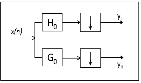
A1-D𝐷𝑊𝑇 decomposes a signal into low frequency and high frequency components. A single stage of image decomposition can be implemented by successive row and column wavelet transforms. One level of
represented in Fig. 1.
Fig. 1.Representation of one level of 1-D𝑫𝑾𝑻 operation.
Fig. 2.shows the block diagram representation of 2-D𝐷𝑊𝑇. The signal is separately processed for the row and columns.
Fig. 2. Representation of one level of 2-D𝑫𝑾𝑻 operation
A 2-D𝐷𝑊𝑇 can be considered as a combination of two 1-D𝐷𝑊𝑇in the 𝑥, and 𝑦 directions. A 2-D𝐷𝑊𝑇 processor is designed by building 1-D𝐷𝑊𝑇 modules composed of high-pass and low-pass filters. These filters perform the convolution of filter coefficients and input data stream. After a one-level of 2-D discrete wavelet transform, the volume of image is decomposed into
𝐻𝐻, 𝐻𝐿, 𝐿𝐻 and 𝐿𝐿 signals as shown in Fig. 2. Image compression applications mostly use the
𝐿𝑒 − 𝐺𝑎𝑙𝑙’𝑠 5/3 filter and the 𝐷𝑎𝑢𝑏𝑒𝑐𝑖𝑒𝑠 9/
7filter. These filters are also accepted as standard filters in the JPEG2000 standard. The JPEG2000 compression
standard uses the biorthogonal𝐿𝑒 − 𝐺𝑎𝑙𝑙 5/3 wavelet for lossless compression and a 𝐷𝑎𝑢𝑏𝑒𝑐𝑖𝑒𝑠 9/
7wavelet for lossy compression. Both the wavelets are from the family of Cohen-Daubechies-Feauveau (𝐶𝐷𝐹) wavelets. The primary generator polynomial for the
𝐶𝐷𝐹 wavelets is a B-spline. All the generators and wavelets in this family are symmetric. For every positive integer 𝐴 there exists a unique polynomial 𝑄𝐴 𝑋 of degree 𝐴 − 1 satisfying the identity,
1 − 𝑋/2 𝐴𝑄
𝐴 𝑋 + 𝑋/2 𝐴𝑄𝐴 2 − 𝑋 = 1 ( 1 )
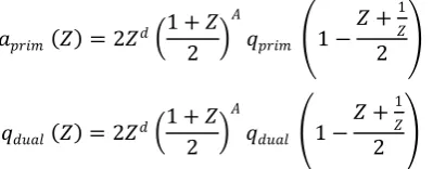
This polynomial is used for the construction of 𝐶𝐷𝐹 wavelets with 𝑄𝐴 𝑋 factorized as
Then, (3) form a biorthogonal pair of scaling sequences
𝑎𝑝𝑟𝑖𝑚 𝑍 = 2𝑍𝑑 1 + 𝑍
2 𝐴
𝑞𝑝𝑟𝑖𝑚 1 − 𝑍 +1𝑍
2
𝑞𝑑𝑢𝑎𝑙 𝑍 = 2𝑍𝑑 1 + 𝑍
2 𝐴
𝑞𝑑𝑢𝑎𝑙 1 − 𝑍 +1𝑍
2
( 3 )
For𝐴 = 2, we get the 𝐿𝑒 − 𝐺𝑎𝑙𝑙’𝑠 5/3 filter and 𝐴 = 4gives the 𝐷𝑎𝑢𝑏𝑒𝑐𝑖𝑒𝑠 9/7 filter as tabulated in Table 1.
𝐿𝑒 − 𝐺𝑎𝑙𝑙’𝑠filter has low latency but provides lesser image compression. On the other hand, the bi-orthogonal
𝐷𝑎𝑢𝑏𝑒𝑐𝑖𝑒𝑠 9/7 filter has symmetric scaling and wavelet functions and has excellent image compression capabilities [24].Another noteworthy comparison is that the image reconstruction quality is better in the case of
𝐿𝑒 − 𝐺𝑎𝑙𝑙’𝑠 filter when compared to the 𝐷𝑎𝑢𝑏𝑒𝑐𝑖𝑒𝑠 9/7 filter proved in [24].
Table 1. CDFWavelet Construction.
CLASS A 𝑄𝐴(𝑋) 𝑞𝑝𝑟𝑖𝑚(𝑋) 𝑞𝑑𝑢𝑎𝑙(𝑋)
𝐿𝑒 − 𝐺𝑎𝑙𝑙’𝑠 5/3 2 1 + 𝑋 1 1 + 𝑋
𝐷𝑎𝑢𝑏𝑒𝑐𝑖𝑒𝑠 9/7 4
1 + 2𝑥
+ 5/2𝑋2
+ 5/2𝑋3 1 − 𝑐𝑋
1 + 𝑐 + 2 𝑋
+ 𝑐2+ 2𝑐
+ 5/2 𝑋2
2. Convolutional versus Lifting Method
There are two main approaches of implementing a 1-D 𝐷𝑊𝑇 : the traditional convolutional based implementation [13] and the lifting based implementation [10], [3].
A. Convolutional 1D DWT
In the conventional convolution based1-D 𝐷𝑊𝑇, two analysis filters, low pass () and high pass (𝑔) are used. The data stream 𝑥[𝑛] is decomposed into the low frequency and the high frequency signal components. The filtering operation is followed by the
downsampling operation which has to be done at the full sampling rate and half of the calculated coefficients have to be discarded due to redundancy. An improvement over this approach was made by the researches in the filter bank design where the execution was accelerated using a polyphase matrix of the filter bank instead of the conventional filtering-downsampling structure. In this case the downsampling is done prior to filtering and hence the requirement to compute redundant coefficients is negated. The polyphase components of the signal are filtered by the corresponding filter coefficients parallely.
The polyphase matrix is defined as:
𝐸0 𝑧 = 𝐻𝐺𝑒 𝑍 𝐻𝑜 𝑍 𝑒 𝑍 𝐺0 𝑍
( 4 )
The variables𝐻𝑒 𝑍 and 𝐻𝑜 𝑍 denote the even and odd polyphase components of the low pass analysis filter and 𝐺𝑒 𝑍 and 𝐺0 𝑍 denote the even and odd polyphase components of the high pass analysis filter. With the polyphase matrix, the wavelet decomposition for the signal can be expressed as:
𝐿𝑃 𝑍
𝐻𝑃 𝑍 = 𝐸0 𝑧 𝑋𝑋𝑒 𝑍 0 𝑍
( 5 )
the even and odd polyphase components of the signal stream. This method of convolutional 1-D 𝐷𝑊𝑇 suffers from high computational complexity and requires higher memory resources.
B. Lifting based 1-D 𝐷𝑊𝑇
In lifting scheme, the polyphase matrix of𝐷𝑊𝑇 is factorized into elementary matrices which reduces the computational complexity of the transformation. For a perfect reconstruction filter pair 𝐻, 𝐺 , [10] proved that it is possible to factor the polyphase matrix 𝐸0 𝑧 lifting steps as:
𝐸 𝑧 = 𝐾0 1/𝐾 0 1 𝑈𝑖 𝑍
0 1
𝑚
𝑖=1
1 0
−𝑃𝑖 𝑍 1 ( 6 )
Where𝐾 is a constant and 𝑚 is the number of predict and update steps.
The forward lifting scheme is depicted in Fig. 3 and consists of the following steps.
a. Decomposition:
This step splits a signal (of even length) into two sets of coefficients, with even index indicated by𝑒𝑣𝑒𝑛𝑗 +1 and odd index indicated by𝑜𝑑𝑑𝑗 +1. This is called the lazy wavelet transform.
b. Prediction:
As the even and odd coefficients are correlated, we can predict one from the other. More specifically, a prediction operator 𝑃 is applied to 𝑒𝑣𝑒𝑛 coefficients and the result is subtracted from the 𝑜𝑑𝑑 coefficients to get the detail signal 𝑑𝑗 +1
𝑑𝑗 +1 = 𝑜𝑑𝑑𝑗 +1− 𝑃 𝑒𝑣𝑒𝑛𝑗 +1 ( 7)
Fig.3.Lifting based 1-D𝑫𝑾𝑻 implementation [11]
c. Update:
An update operator 𝑈 is applied to the 𝑜𝑑𝑑 coefficients and added to the 𝑒𝑣𝑒𝑛 coefficients to define 𝑐𝑗 +1
𝑐𝑗 +1 = 𝑒𝑣𝑒𝑛𝑗 +1+ 𝑈 𝑑𝑗 +1 ( 8)
d. Scaling:
To ensure normalization, the approximation band 𝑐𝑗 +1 is scaled by a factor of 𝐾, and the detail band 𝑑𝑗 +1by a factor of 1 𝐾.
The defining equations for the lifting method are given by (9)-(11)
𝑑𝑖1= 𝛼 𝑥𝑒 𝑖 + 𝑥𝑒 𝑖 + 1 + 𝑥0 𝑖 𝑎𝑖1= 𝛽 𝑑𝑖1+ 𝑑𝑖−11 + 𝑥𝑒 𝑖
( 9)
𝑑𝑖2= 𝛾 𝑎𝑖1+ 𝑎𝑖+11 + 𝑑𝑖 1 𝑎𝑖2= 𝛿 𝑑𝑖2+ 𝑑𝑖−12 + 𝑎𝑖1
𝑌𝐿= 𝜁𝑎𝑖2 𝑌𝐻 = 1/𝜁 𝑑𝑖2
( 11 )
Equation (9) gives thepredict(𝑃1: 𝑑𝑖1)and update (𝑈1: 𝑎𝑖1) values for the first stage of lifting and (10) gives the predict and (𝑃2: 𝑑𝑖2) update (𝑈2: 𝑎𝑖2) values for the second stage of lifting. Equation (11) is the scaling equation.
The beauty of the lifting transform is that the inverse
𝐷𝑊𝑇 transform can be implemented by simply computing from right to left and switching the signs of the predict and update operators and scaling factors. The lifting based 𝐷𝑊𝑇implementation is preferred because of the lower computational complexity and the flexibility offered in terms of factorization and perfect reconstruction property.
A comparison of Biorthogonal 9/7 filter
implementaiton using the convolutional and the lifting method [11] shows that the lifting architecture results in smaller and faster hardware with lower energy consumption compared to the convolutional architecture.
IV. Proposed
𝑝𝑜𝑙𝑦 − 𝐷𝑊𝑇
Architecture
While the 𝐷𝑢𝑎𝑏𝑒𝑐𝑖𝑒𝑠 9/7 filter provides high compression performance, it also leads to a lossy compression. This results from the truncation of the irrational filter coefficientsin a fixed-point hardware implementation. 𝐿𝑒 − 𝐺𝑎𝑙𝑙’𝑠 5/3filter provides an inferior but a lossless compression performance.
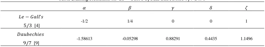
Table 2.Lifting coefficients for 𝐿𝑒 − 𝐺𝑎𝑙𝑙’𝑠 5/3&𝐷𝑎𝑢𝑏𝑒𝑐𝑖𝑒𝑠’9/7 𝐷𝑊𝑇
𝛼 𝛽 𝛾 𝛿 𝜁
𝐿𝑒 − 𝐺𝑎𝑙𝑙’𝑠
5/3 [4] -1/2 1/4 0 0 1
𝐷𝑎𝑢𝑏𝑒𝑐𝑖𝑒𝑠
9/7 [9] -1.58613 -0.05298 0.88291 0.4435 1.1496
In this article an𝑝𝑜𝑙𝑦 − 𝐷𝑊𝑇 architecture is proposed with features for dynamic allocation of hardware resources and switching between 5/3 and
9/7 wavelet structures in run-time. The proposed
𝑝𝑜𝑙𝑦 − 𝐷𝑊𝑇 architecture has the following features.
A. Lifting Based Implementation:
The wavelet architectures for 5/3 and 9/7filters is implemented using lifting scheme as against the convolutional implementation in [2].
B. Dynamic Resource Allocation:
The architecture provides features for dynamic allocation of resources to meet the requirements of the changing external conditions. The architecture can switch between the lossless 5/3 and the lossy 9/7 architecture during run-time.
C. Scaled Coefficients:
The filters design uses rounding and scaling of the coefficients. The advantage of this process is that the arithmetic units operate on integer samples and thus reduces complexity of the hardware.
The basic lifting method is described by the predict, update and the scaling equations operating on 𝑒𝑣𝑒𝑛 and 𝑜𝑑𝑑 samples of the input data stream. The lifting
coefficients for the 𝐿𝑒 − 𝐺𝑎𝑙𝑙 5/3
and𝐷𝑎𝑢𝑏𝑒𝑐𝑖𝑒𝑠 9/7 𝐷𝑊𝑇 are tabulated in Table 2. Basic lifting algorithm uses fractional coefficients and hence requires adders and multipliers to operate upon fixed/ floating point numbers. The proposed modified lifting method uses integer coefficients and hence the adders and multipliers used operate upon integers and are simpler to implement.
In the proposed 𝑝𝑜𝑙𝑦 − 𝐷𝑊𝑇 method the
𝐿𝑒 − 𝐺𝑎𝑙𝑙 5/3 filter is implemented using the lifting approach. The equations for the lifting based 𝐿𝑒 −
𝐻𝑃 2𝑛 + 1 = 𝑋 2𝑛 + 1 − 𝑋 2𝑛 + 𝑋 2𝑛 + 2 2
𝐿𝑃 2𝑛 = 𝑋 2𝑛 − 𝐻𝑃 2𝑛 − 1 + 𝑋 2𝑛 + 1 + 2 4
( 12 )
Where 𝑋[. ]are the signal samples, 𝐻𝑃 and 𝐿𝑃are the high frequency and low frequency outputs. The division by 2 and 4 are realized using shift operations.
The 𝐷𝑎𝑢𝑏𝑒𝑐𝑖𝑒𝑠 𝑓𝑖𝑙𝑡𝑒𝑟 9/7 has irrational coefficients which are tough to implement in hardware. Hence, a set of binary coefficients in close proximity of the 𝐶𝐷𝐹 9/7 filter are used for the hardware implementation [2]. The expressions for 𝑖𝑔 and 𝑙𝑜𝑤 outputs with the approximate coefficient values are given by (13).
𝑖𝑔9
7 𝑖 = 𝑥 𝑖 − 9 16𝑤1+
1 16𝑤3
𝑙𝑜𝑤9 7 𝑖 =
23 32𝑥 𝑖 +
1 4𝑤1−
1 8𝑤2+
1 64𝑤4
( 13 )
Where,
𝑤0= 𝑥 0 𝑤1 = 𝑥 𝑖 − 1 + 𝑥 𝑖 + 1 𝑤2 = 𝑥 𝑖 − 2 + 𝑥 𝑖 + 2 𝑤3 = 𝑥 𝑖 − 3 + 𝑥 𝑖 + 3 𝑤4 = 𝑥 𝑖 − 4 + 𝑥 𝑖 + 4
( 14 )
The 𝐷𝑎𝑢𝑏𝑒𝑐𝑖𝑒𝑠 𝑖𝑔 and𝑙𝑜𝑤 outputs in terms of the 𝐿𝑒 − 𝐺𝑎𝑙𝑙 5/3 outputs are given by (15).
𝑖𝑔97 𝑖 = 1
2× 𝑖𝑔53 𝑖 − 1
32× 𝑤1+ 1 32× 𝑤3
𝑙𝑜𝑤97 𝑖 = 𝑙𝑜𝑤53 𝑖 − 1
32× 𝑤0+ 1/64 × 𝑤4
( 15 )
The proposed 𝑝𝑜𝑙𝑦 − 𝐷𝑊𝑇 architecture for implementing 1-D 𝐷𝑊𝑇 transform is presented in Fig. 4. The architecture uses the backbone of the basic lifting architecture for computing the 𝐿𝑒 − 𝐺𝑎𝑙𝑙 5/3 𝐷𝑊𝑇. The 𝐷𝑎𝑢𝑏𝑒𝑐𝑖𝑒𝑠 9/7 𝐷𝑊𝑇 is computed by selecting the extra hardware resources as shown in Fig 4.
The salient modifications proposed in the present architecture as compared to the conventional lifting architecture are as follows:
1. A single architecture implementation is used for both 𝐿𝑒 − 𝐺𝑎𝑙𝑙 5/3 and 𝐷𝑎𝑢𝑏𝑒𝑐𝑖𝑒𝑠 9/7 𝐷𝑊𝑇 allowing on the fly selection between the two transforms.
2. 𝐷𝑎𝑢𝑏𝑒𝑐𝑖𝑒𝑠 9/7 𝐷𝑊𝑇 computations are implemented in terms of 𝐿𝑒 − 𝐺𝑎𝑙𝑙 5/3 𝐷𝑊𝑇 allowing hardware sharing.
3. Multiplication and division operations are decomposed into shifting operations which reduces the requirement of multipliers.
4. The architecture uses integer lifting coefficients. Hence the adders and multipliers work on integer operands
5. The architecture can switch between 𝐿𝑒 −
𝐺𝑎𝑙𝑙 5/3 and𝐷𝑎𝑢𝑏𝑒𝑐𝑖𝑒𝑠 9/7 𝐷𝑊𝑇. By default
𝐿𝑒 − 𝐺𝑎𝑙𝑙 5/3 𝐷𝑊𝑇 is computed.
V. Implementation Results
This section presents quantitative results for the
performance of 𝑃𝑜𝑙𝑦 − 𝐷𝑊𝑇 architecture presented in this article. The proposed architecture is implemented on a XILINX XC5VLX30 FPGA hardware. The polymorphic 𝐷𝑊𝑇 architecture is analyzed in terms of the image reconstruction and FPGA area considerations.
A. Image Reconstruction Quality
The proposed 𝑝𝑜𝑙𝑦 − 𝐷𝑊𝑇 architecture was evaluated for different test images for the image reconstruction quality studies. The image reconstruction was achieved by forward and inverse 𝑝𝑜𝑙𝑦 − 𝐷𝑊𝑇 architectures implemented in the same hardware. Results of the test are compiled in Table 3. The
𝑝𝑜𝑙𝑦 − 𝐷𝑊𝑇 design achieves a good 𝑃𝑆𝑁𝑅 value for the test images in the range of 48 𝑑𝐵 for
𝐿𝑒 − 𝐺𝑎𝑙𝑙 5/3 filter. As expected, because the
𝐷𝑎𝑢𝑏𝑒𝑐𝑖𝑒𝑠 9/7 filter gives a lossy compression, the𝑃𝑆𝑁𝑅 value for the same test cases was poorer by a few dB. The results obtained are in correlation to the existing findings published in [24].
Table 3. Image reconstruction quality for the proposed 𝑝𝑜𝑙𝑦 − 𝐷𝑊𝑇 architecture
Test Image PSNR 𝐿𝑒 − 𝐺𝑎𝑙𝑙 5/3 (dB)
PSNR 𝐷𝑎𝑢𝑏𝑒𝑐𝑖𝑒𝑠 9/7 (dB)
Lena 22.5 20.3
Boat 23.5 21.4
Elaine 48.1 45.7
Cat 48.1 45.4
Lake 46.2 44.3
Pirate 48.2 46.1
B.Synthesis Results
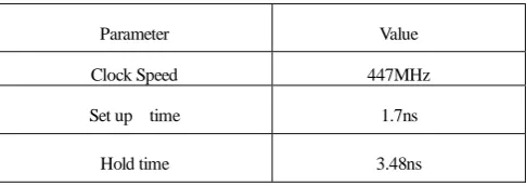
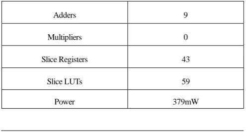
The synthesis results of proposed architecture are tabulated in Table 4. The 𝑝𝑜𝑙𝑦 − 𝐷𝑊𝑇 architecture achieves a clock speed of 447MHz. As is obvious from the analytical equations, 9 adders are used. With the use
of approximated coefficients, the multiplication operations are carried out by shift operations and hence no dedicated multiplier is used. The static power consumption of the architecture is379mW.
Table 4. Synthesis results for the proposed 𝑝𝑜𝑙𝑦 − 𝐷𝑊𝑇architecture
Parameter Value
Clock Speed 447MHz
Set up time 1.7ns
Adders 9
Multipliers 0
Slice Registers 43
Slice LUTs 59
Power 379mW
A comparison of the proposed architecture with other designs reported in literature is summarized in Table 5. The design achieves the maximum clock rate of 447MHzwith minimum hardware requirements. The advantage of reduced hardware is due to the reusability of the hardware resources for 5/3 and 9/7 implementation.
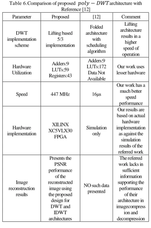
It is also imperative to present a comparison of our work with one of the similar works reported in literature in [12]. The following paragraphs present the comparison.
1.Our work presents the results of the actual hardware implementation of the proposed architecture on XILINX XC5VLX30 FPGA hardware, whereas, the referred work in [12] has presented the results based on the simulation studies using Modelsim and Quartussoftware’s.
2.In our work, dedicated adders are used for all addition operations as against thescheduling based implementation in [12]. The result ofnot scheduling and utilizing dedicated hardware is an increase in the operationspeed of the 𝐷𝑊𝑇 core at the expense of an increase in the power consumption.This is evident from the presented results as well (Power: [12] 50mW, Our work 380mW, Speed: [12] few MHz,Ourwork 447MHz). The higher speed of operation is also achieved due to thelifting architecture used for the 5/3 filter implementation.
3.Our work, presents the compression performance of the 𝑝𝑜𝑙𝑦 − 𝐷𝑊𝑇 core for some standard test images. The image reconstruction results are presented in Table 3. The results hence support the claims presented in the paper and also earmark, the difference between 5/3 and 9/7 image reconstruction. No such details are available in the referred work.
Table 5.Comparison of proposed architecture with other designs
Features Proposed
Dau bechi es 9⁄7
[2] [21] [11] [22] [23]
Clock Speed
(MHz) 447 107 389 - - - 200
Adders 9 15 9 19 15 8 19
Multipliers 0 9 0 0 0 4 0
Slice Registers 43 144 208 - - - -
Slice LUTs 59 80 175 - - - -
PSNR A A B C C A B
Table 6.Comparison of proposed 𝑝𝑜𝑙𝑦 − 𝐷𝑊𝑇architecture with Reference [12]
Parameter Proposed [12] Comment
DWT implementation scheme Lifting based 5/3 implementation Folded architecture with scheduling algorithm Lifting architecture
results in a higher speed of operation Hardware Utilization Adders:9 LUTs:59 Registers:43 Adders:9 LUTs:172 Data Not Available
Our work uses lesser hardware
Speed 447 MHz 16μs
Our work has a much better speed performance Hardware implementation XILINX XC5VLX30 FPGA Simulation only
Our results are based on actual
hardware implementation
as against the simulation results of the referred work Image reconstruction results Presents the PSNR performance of the reconstructed image using the proposed design for DWT and IDWT architectures
NO such data presented
The referred work lacks in
sufficient information supporting the performance of their architecture in imagecompress ion and decompression
4.We have achieved a faster operation than the referred work [12] with the same number of adders and lesser number ofLUTs.
5.Our work is compared with the similar works discussed in paper. The comparison results are presented in Table 5 and 6. Based on the results it can be concluded that the proposed 𝑝𝑜𝑙𝑦 − 𝐷𝑊𝑇architecture is better in terms of the lower hardware resource requirements, higher speed. Noteworthy image reconstruction quality is also observed in the proposed 𝑝𝑜𝑙𝑦 − 𝐷𝑊𝑇architecture.
VI. Conclusions
In this article a𝑝𝑜𝑙𝑦 − 𝐷𝑊𝑇 architecture for the
implementation of 𝐿𝑒 − 𝐺𝑎𝑙𝑙 5/3 and
𝐷𝑎𝑢𝑏𝑒𝑐𝑖𝑒𝑠 9/7 filters is presented. The concept of hardware reusability, dynamic allocation and the lifting scheme adoption are the salient features of the architectures proposed by the authors. The hardware dynamic allocation ensures on the fly switch over from
𝐿𝑒 − 𝐺𝑎𝑙𝑙’𝑠 computation to 𝐷𝑎𝑢𝑏𝑒𝑐𝑖𝑒𝑠 computation with some finite latency. The 𝐿𝑒 −
𝐺𝑎𝑙𝑙 hardware is used as it is in the
𝐷𝑎𝑢𝑏𝑒𝑐𝑖𝑒𝑠implementation, the hardware resources requirements are dramatically reduced. The concept of approximate filter coefficients as proposed in [2] was also used to simplify the adder implementation. Also, the design achieves a multiplier less implementation as the multiplication operations are carried out using shift operations. The proposed design achieves a clock frequency of 447 MHz and a good PSNR performance for both 𝐿𝑒 − 𝐺𝑎𝑙𝑙 and 𝐷𝑎𝑢𝑏𝑒𝑐𝑖𝑒𝑠 filters.A comparison with the similar works reported in the literature is presented in Table 5 and 6. It is evident from the comparisons that the proposed design is superior in terms of the hardware performance as well as PSNR performance.
As a future work, the design can be extended for “bit width” switching as proposed in [2].
References
[1] D. Lie, K. Chae, and S. Mukhopadhyay, "Analysis of the
Performance, Power, and Noise Characteristics of a CMOS Image
Sensor With 3-D Integrated Image Compression Unit," IEEE
pp.198-208.
[2] A. Pande and J. Zambreno , “Poly-DWT: polymorphic wavelet hardware support for dynamic image compression,” ACM
Transactions on Embedded Computing Systems., vol. 11, no.1,
Mar. 2012, pp.6.
[3] Yusong Hu, and ChingChuen Jong, "A Memory-Efficient
High-Throughput Architecture for Lifting-Based Multi-Level 2-D
DWT," IEEE Trans. Signal Process., vol. 61, no.20, Oct. 2013,
pp.4975-4987.
[4] M.E.Angelopoulou et al. “Implementation and comparison of the
5/3 lifting 2D discrete wavelet transform computation schedules on FPGAs,” J Signal Process Sys., vol. 51, no.1, Apr. 2008,
pp.3–21.
[5] A. Darji, et al., "Dual-Scan Parallel Flipping Architecture for a
Lifting-Based 2-D Discrete Wavelet Transform," IEEE Trans.
Circuits Syst.II., vol.61, no.6, June.2014, pp.433-437.
[6] M. Alam, et al. "Efficient distributed arithmetic based DWT
architecture for multimedia applications," System-on-Chip for
Real-Time Applications, 2003. Proceedings. The 3rd IEEE
International Workshop on , vol., no.,2003 pp.333-336
[7] S.J. Choi and J.W.Woods, “Motion-compensated 3-D subband coding of video,” IEEE Trans. Image process., vol.8, no.2, Feb
1999, pp.155–167.
[8] D. Stroobandt, et al., “Reconfigurable hardware for a scalable
wavelet video decoder and its performance requirements”, In
Computer Systems: Architectures, Modeling, and Simulation, D.
Stroobandt, et al, Springer, Volume 3133, 2004, pp 203-212. [9] A. Das, A. Hazra, and S. Banerjee, “An Efficient Architecture for 3-D
Discrete Wavelet Transform,” IEEE Trans. Circuits Syst. Video
Technol. , vol.20, no.2, Feb. 2010, pp.286–296.
[10] I. Daubechies and W. Sweldens, “Factoring wavelet transforms into lifting steps,” J. Fourier Anal. Appl., vol. 4, no.3, Sep. 1998, pp.
247–269.
[11] K.A. Kotteriet al., “A comparison of hardware implementations of the biorthogonal 9/7 DWT: convolution versus lifting,” IEEE
Trans. Circuits Syst.II., vol. 52, no.5, May. 2005, pp. 256–260. [12] R. Lavanya, and B. Saranya, “High Speed, Low Complexity,
Folded, Polymorphic Wavelet Architecture Using Reconfigurable Hardware,” Int. J. Comput. Appl. T., vol. 2, no.5, June 2010, pp.
1-4.
[13] S.G.Mallat, “A theory for multiresolution signal decomposition: the wavelet representation,” IEEE Trans. Pattern Anal. Mach. Intell.,
vol.11, no.7, July. 1989, pp.674–693.
[14] R. Qiu and W. Yu, “An efficient quality scalable motion-JPEG2000 transmission scheme” Washington University, Department Of
Computer Science, WUCS-01-37,2001, pp. 1-9.
[15]A.Said, and W.A.Pearlman, “An image multiresolution representation for lossless and lossy compression,” IEEE Trans.
Image Process., vol. 5, no.9, Sep. 1996, pp.1303–1310. [16] J.M.Shapiro, “Embedded image coding using zerotrees of wavelet
coefficients,” IEEE Trans. Signal Process., vol. 41, no.12, Dec.
1993, pp.3445–3462.
[17] T.Y Sung, H.CHsin, Y.-S. Shieh, and C.-W. Yu, "Low-Power
Multiplierless 2-D DWT and IDWT Architectures Using 4-tap
Daubechies Filters," Parallel and Distributed Computing,
Applications and Technologies, 2006. PDCAT '06. Seventh
International Conference on , vol., no.,2006, pp.185-190
[18] Jian-aoLian; Yonghui Wang, "Energy Preserving QMF for Image
Processing," IEEE Trans. Image Process., vol.23, no.7, July
2014, pp.3166,3178.
[19] P. Kumar, A. Mittal and P. Kumar, “Fusion of thermal infrared and visible sprectrum video for robust surveillance”. Proceedings of
the 5th Indian Conference on Computer Vision, Graphics and
Image Processing (ICVGIP '06), Volume 4338, 2006, pp
528-539
[20] W.Yang, et al., “4-D wavelet-based multiview video coding,” IEEE
Trans. Circuits Syst. Video Technol., vol.16, no.11, Nov 2006, pp.
1385-1396.
[21] D. Tay, “Rationalizing the coefficients of popular biorthogonal wavelet filters,” IEEE Trans. Circuits Syst. Video Techno., vol.
10, no.6, Sep. 2000, pp.998–1005.
[22] C.-T. HUANG, P.-C. TSENG,, AND L.-G. CHEN, “VLSI
architecture for discrete wavelet transform based on B-spline factorization”. In Proceedings of the IEEE Workshop on Signal
Processing Systems (SIPS).IEEE,2003, pp.346–350.
[23] M. Martina, AND G. Masera, “Multiplierless, folded 9/7 - 5/3 wavelet VLSI architecture,” IEEE Trans.Circuits Syst. II., vol. 54,
no.9, Sep. 2007, pp.770–774.
[24] C. Christopoulos, A. Skodras, and T. Ebrahimi, “The JPEG2000
still image coding system: an overview," IEEE Trans. Consum.
Electron., vol.46, no.4, Nov 2000, pp.1103-1127.
[25] X. Zhao, A.T. Erdogan, and T. Arslan, "High-Efficiency
Customized Coarse-Grained Dynamically Reconfigurable
Architecture for JPEG2000 IEEE Trans. Very Large Scale Integr.