IJEDR1904105 International Journal of Engineering Development and Research (www.ijedr.org) 628
PV System Control using Power Electronic
Converters
1M Suneel, 2P Chaithanya Kumar
1PG Scholar, Dept. of EEE, 2Assistant Professor, Dept. of EEE Gokula Krishna College of Engineering, Sullurpet
_____________________________________________________________________________________________________
Abstract - The power electronic converters plays crucial role in conversion and control of the electrical power. The
production of solar energy is based on the idea of converting a type of energy mostly solar energy into electrical energy. The most appealing renewable energy source is photovoltaic which transform the solar energy into DC electrical energy. Power electronics converters are used to control frequency and magnitude of the current resultant from the conversion between energies. The objective of this paper is to model and control of transformer-less grid connected PV system with Hysteresis controller which can be used to supply the electric power to utility grid. This system uses two stage conversion process. DC to DC stage which utilizes MPPT technique to extract the maximum power. DC to AC which used to control inverter output by using hysteresis Current controller. The problem of maximum power transferring is enhanced by using Incremental conductance algorithm and phase locked loops are utilized in conjunction to make supply in synchronization with the grid which reduces the two problems described. The studied system is modeled and simulated in the MATLAB/SIMULINK environment.
keywords - PV Grid, Solar Power Systems, Solar Cells, Power Electronic Converters
_____________________________________________________________________________________________________ I. INTRODUCTION
The worldwide electrical energy consumption is increasing exponentially. To meet this rising demand, it is necessary to install more power plants. But, since fossil fuels reserves are finite and it's just a matter of time before they will run out, needless to mention their contribution in global warming, many countries are now examining their national energy policies and looking to embrace other alternatives. Renewable energies are among the energy sources that offer another way to avoid this fossil energy deadline. They are also expected to play an important role as a clean electricity power source in the future energy demands.
Energy from a source that is not depleted when used is known as renewable energy source. Such as solar or wind power. One major advantage of renewable energy is that it is sustainable and will never run out. They provide clean energy because they are non-pollutant and non-contributor to greenhouse effects and global warming. Renewable energy facilitates generally require less maintenances than traditional facilities generators. Their fuel being derived from natural and available resources reduces the costs of operation. Renewable energy produces little or no waste products such as carbon dioxide or other chemical pollutants, so have a minimal impact on the environment. Renewable energy projects can also bring economic benefits to many regional areas, as most projects are located away from large urban center and suburbs of the capital cities. These economic benefits may be from the increased use of local services.
IJEDR1904105 International Journal of Engineering Development and Research (www.ijedr.org) 629 Fig. 1 Block diagram of Basic Grid connected PV system
II. GRID CONNECTED PVSYSTEM
The grid-connected PV application presents generally two problems,
• The first problem is the achieving the MPPT controller in order to maximize the delivered power regardless of the climatic conditions or the load variation.
• The second problem is the synchronization with the utility grid.
Considerable efforts have been made into the control of these systems. The most common control strategies structures applied to this decentralized power generator is based on Power-Angle Control (PAC) which is also called Voltage-Angle Control (VAC), Voltage Oriented Control, P-Q Control, or Decoupled Current Control. Another Active Power Control using a robust nonlinear adaptive back stepping approach. But, these researches have been done using PEC regardless of their models type (detailed or averaged). The switching model (detailed model) is modelled with IGBT/diode pairs controlled by pulses, produced by a Pulse Width Modulation (PWM) generator. This model provides the most accurate simulation results, but takes a long simulation time. Further, it cannot give satisfaction for the analysis of small-signal due to its discrete behaviour.
While, average value modelling further simplifies PEC representation by neglecting the switching effects. Indeed, the average model is modelled using a switching function (SF) directly controlled by reference voltage (uref) or by duty cycle (d) (0 < d < 1).
Therefore, in average model case, there is no need to implement a PWM generator block that requires high switching frequency (f). That's why this model provides faster simulations than the detailed. In addition, these models are also useful to predict converter steady-state characteristics and small-signal dynamics in discontinuous conduction mode (DCM). Also, and in spite of its disadvantages, the average model remains often useful before the final control design. It is considered a good compromise between complexity, computation time and acceptable accuracy for system simulation. Due to these advantages, the average models of the both PEC are used in this paper in order to accelerate the simulation.
III. VOLTAGE SOURCE INVERTER
Inverters are static power converters that produce an AC output waveform from a DC power supply. They are applied in adjustable AC speed drives, Uninterruptible Power Supplies (UPS), shunt active power filter, etc. For sinusoidal AC outputs, the magnitude, frequency, and phase should be controllable. If a DC input is a voltage source, then the inverter is called a Voltage Source Inverter (VSI). According to a number of phases, inverters are classified into two types.
1. Single Phase Voltage Source Inverter 2. Three Phase Voltage Source Inverter
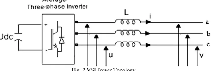
The typical three-phase VSI topology is shown in Fig. 2.
Fig. 2 VSI Power Topology.
From the loop equation for voltages in the circuit described in Fig. 2. Let U be the inverter output voltages and V be the grid voltages then, the 3- phase voltages are given as
PV Module
DC-DC
Converte
r
Inverter
GridVSC
−
=
c b a
c b a
c b a
i
i
i
dt
d
L
V
V
V
IJEDR1904105 International Journal of Engineering Development and Research (www.ijedr.org) 630
I
i
dt
dv
C
dcc
+
=
abc abc
U
Ri
dt
di
L
( )+
=
[
]
0
=
+
+
b ca
i
i
i
where abcU
]
[
=
[
V
]
abc-
[
U
]
abcApplying the transformation method from three phase system abc to rotating frame dq
+
−
+
−
−
−
−
=
c b a q dX
X
X
t
t
t
t
t
t
X
X
]
3
2
sin[
]
3
2
cos[
]
3
2
sin[
]
3
2
cos[
sin
cos
To the current [i]abc , the equations are given as follows
+
+
−
+
=
3
2
cos
3
2
cos
cos
t
i
t
i
t
i
I
d q b C
+
+
−
+
−
=
3
2
sin
3
2
sin
sin
t
i
t
i
t
i
I
q a b CAnd similarly to the voltage [
Uabc ],the equations are given follows
+
+
−
+
−
=
3
2
cos
3
2
sin
sin
t
U
t
U
t
U
U
d d b C
+
+
−
+
−
=
3
2
cos
3
2
sin
sin
t
U
t
U
t
U
U
q a b CIf we apply the derivative to (3.)
+
+
−
+
−
+
+
−
+
=
3
2
sin
3
2
sin
sin
3
2
cos
3
2
cos
cos
t
i
t
i
t
i
t
dt
di
t
dt
di
t
dt
di
dt
dI
c b a c b a dUsing above equations,
IV. SIMULINK MODEL OF BOOST CONVERTER
The Fig. 3 shows the boost converter design in Simulink and corresponding waveforms are shown in Fig. 4.
1
dq d q
dI
R
I
I
U
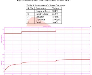
IJEDR1904105 International Journal of Engineering Development and Research (www.ijedr.org) 631 Fig. 3 Simulink Model of Boost Converter without MPPT
Table. 1 Parameters of a Boost Converter S. No. Parameters Values 1. Output voltage 500 V 2. Input voltage 263 V
3. Inductor 15 Mh
4. Capacitor 1500 µH
5. Load 100Ω
IJEDR1904105 International Journal of Engineering Development and Research (www.ijedr.org) 632 Fig. 5 Output Voltage of Boost Converter without MPPT.
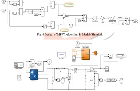
V. SIMULINK MODEL OF MPPTALGORITHM
The MPPT Algorithm used in this model is incremental conductance. This model is mostly used due to its higher tracking ability and can operate at different climatic conditions efficiently.
Fig. 6 Design of MPPT Algorithm in Matlab/Simulink.
IJEDR1904105 International Journal of Engineering Development and Research (www.ijedr.org) 633 Fig. 8 Tracking characteristics of Incremental Conductance.
The Fig. 8 shows the adjusting of duty cycle with accordance to irradiance. From 0 to 1 seconds the irradiance (G) is 600 w/m2
and Temperature is 25 0C, Maximum Power is 1218W and Maximum Voltage is 280V. From 1 to 3 seconds, G = 800 w/m2,
Temperature (T) =250C, Maximum Power is 1615W and Maximum Voltage is 410V. From 3 to 5 seconds, G = 1000 w/m2, T =
250C and Maximum Power =2001W and Maximum Voltage is 440V.
Fig. 9 Output Voltage of Boost Converter with MPPT Algorithm. Table. 2 Comparison of boost converter with & without MPPT Parameters Irradiance(w/m2) Power(W) Voltage(V) Boost Converter with MPPT
600 1218 263
800 1615 264.5
1000 2001 265.8
Boost Converter without MPPT
600 450 200
800 550 230
1000 650 260
From the above table it is clear that boost converter with MPPT gives more Power than the boost converter without MPPT. VI. SIMULINK MODEL OF 2KWGRID CONNECTED PVSYSTEM
Fig. 10 shows the study PV system, composed by:
• KC200GT PV modules which the parameters are shown in Table 3.
• Boost converter and transformer less 3-ph VSI.
• Output self-filter,
• Two controllers blocks that are used respectively for tracking the MPP and to control the amplitude and frequency requirements of the utility AC grid, the line to line grid RMS Voltage VLL=380 V and grid frequency f=50 Hz. Two loads, with:
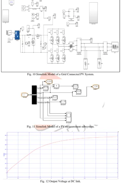
IJEDR1904105 International Journal of Engineering Development and Research (www.ijedr.org) 634 Fig. 10 Simulink Model of a Grid Connected PV System.
Fig. 11 Simulink Model of a PV measurement subsystem.
Fig. 12 Output Voltage at DC link.
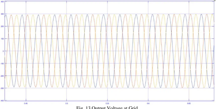
IJEDR1904105 International Journal of Engineering Development and Research (www.ijedr.org) 635 Fig. 13 Output Voltage at Grid.
➢ The line to line voltage of the grid is taken as 380 V (RMS).
➢ From 0 to 0.5 sec the applied irradiance is 600W/m*2, 250 C, the voltage at the load is reduced because at 600W/m*2
PV array able to 1180W but the connected load is 2000W.
From 0.5 sec to 5 sec the applied irradiance is 1000W/m*2, 250C, the voltage at the load increases gradually as increase of the
PV power. VII. CONCLUSION
In this paper simulation is done to study behaviour of the grid-connected residential PV System in order to convert efficiently the solar energy. The simulated model and the results obtained for various operating conditions, show the robustness control approach as well to maintain a constant DC bus voltage. They also demonstrate the tracking accuracy and the fast response with low oscillations of the proposed modified IC algorithm as MPPT technique. PLL is used to make the rotating frame synchronous with grid voltage by extracting the grid angle. It managed to synchronize the system as expected. On the other hand, the transformer-less grid-connected PV system, without storage facilities, using a simple and cheap MPPT controller, can be considered a very interesting topology for residential applications. Indeed, the PV chain devices number is reduced, which mean, less cost and less installation complexity. So, it can make their easy and cheap facilities more attractive in developing countries. The simulation results also indicate that the proposed system provides power to the local loads, regardless of climatic conditions or loads variation. The grid takes care to provide the additional power required by those loads when the PVG cannot supply enough energy. Otherwise, any PVG extra power is injected to the grid. Thus, this proposed residential PV system can be a typical solution to meet an energy demand part and improve the electrical distribution grid.
REFERENCES
[1] N. Lakshmi Tirupathamma, M. Rajesh, K. Naga Vamsi,R., Lohith, P. Sravan Kumar, “Matlab Simulation of Grid Connected PV System Using Hysteresis Current Control Inverter”, International Journal of Research Studies in Computer Science and Engineering (IJRSCSE) Volume. 1, Issue 5, PP 13-20, September 2014.
[2] N.Syam Kumar, Ch.Ravi Kumar , K.Kanaka Raju , P.Guruvulu Naidu, “A New Simulation Approach Of 3-Φ Transformer-less Grid Connected PV Inverter Using Hysteresis Controller”, International Research Journal of Engineering and Technology (IRJET). Volume: 04 Issue: 12, Dec-2017.
[3] Evgenije Adzic, Vlado Porobic, Boris Dumnic, Nikola Celanovic, Vladimir Katic, “PLL Synchronization in Grid Connected Converters,” The 6th PSU-UNS International Conference on Engineering and Technology (ICET-2013), Novi Sad, Serbia, May 15-17, 2013 University of Novi Sad, Faculty of Technical Sciences.
[4] Adžić, E.M., Adžić, M.S., Katić, V.A, “Improved PLL for power generation systems operating under real grid conditions,” Guest Editorial W, 5. ELECTRONICS, VOL. 15, NO. 2, DECEMBER 2011.
[5] Kumar Siddhant, “Implementation of Fractional Open Circuit Voltage MPPT Algorithm in A Low Cost Microcontroller,” Dept. of Electrical Engineering National Institute of Technology, Rourkela.
[6] B.Venkata Ranganadh, A. Mallikarjuna Prasad, Madichetty Sreedhar, “Modelling And Simulation Of A Hysteresis Band Pulse Width Modulated Current Controller Applied To A Three Phase Voltage Source Inverter By Using Mat lab,”
International Journal of Advanced Research in Electrical, Electronics and Instrumentation Engineering, Vol. 2, Issue 9, September 2013.
[7] P. SathishKumar, A. Imtiyas, U. Shyamaladevi, “Induction Motor Driven Water Pump Fed By Solar Photovoltaic Array Using Boost Converter,” International Journal of Mechanical Engineering and Technology (IJMET) Volume 9, Issue 1, January 2018, pp. 336–347, Article ID: IJMET_09_01_036.