Reconstruction of 3D Human Facial Images
Using Partial Differential Equations
Eyad Elyan, Hassan Ugail
University of Bradford/EIMC Department, Richmond Road, BD7 1DP, Bradford, UK Email: {E.Elyan, H.Ugail}@Bradford.ac.uk
Abstract—One of the challenging problems in geometric modeling and computer graphics is the construction of realistic human facial geometry. Such geometry are essential for a wide range of applications, such as 3D face recognition, virtual reality applications, facial expression simulation and computer based plastic surgery application. This paper addresses a method for the construction of 3D geometry of human faces based on the use of Elliptic Partial Differential Equations (PDE). Here the geometry corresponding to a human face is treated as a set of surface patches, whereby each surface patch is represented using four boundary curves in the 3-space that formulate the appropriate boundary conditions for the chosen PDE. These boundary curves are extracted automatically using 3D data of human faces obtained using a 3D scanner. The solution of the PDE generates a continuous single surface patch describing the geometry of the original scanned data. In this study, through a number of experimental verifications we have shown the efficiency of the PDE based method for 3D facial surface reconstruction using scan data. In addition to this, we also show that our approach provides an efficient way of facial representation using a small set of parameters that could be utilized for efficient facial data storage and verification purposes.
Index Terms—Partial Differential Equations, 3D face representation, 3D data storage.
I. Introduction
A 3D geometry of a human face is required for a wide range of applications. Such applications –among many others include 3D face recognition and authentication [1-3], simulation of plastic facial surgery [4], facial expression simulation [5], facial animation [6] and facial morphing [7]. The challenge in developing the facial model is not only to have a model that looks real, but one which also can be efficiently utilized for the specific purpose for which the geometry is created. This is due to the fact that for any application involving the geometry of the face there is a need for manipulation and verification data.
Constructing 3D facial models is a challenging topic which has recently received extensive attention within the research community. Modeling facial data usually depends on the nature of the problem. In other words
when accuracy matters (i.e. in face recognition applications) then accurate geometry models are paramount while simpler geometric models are sometimes preferred for applications that involve faster comparison or data transfer over the networks.
The two mainstreams for acquiring 3D facial data in order to reconstruct facial models are either image based techniques or techniques based on real 3D data acquired by 3D scanners. Image based facial modeling techniques, involve the utilization of one or more 2D images (e.g. images representing frontal and side views of a give face) to construct 3D facial models. These techniques usually involve two steps. The first step is to extract certain features from the facial image [9] and the second step is to modify a generic model or construct a new 3D model [2, 10-12]. Such techniques can easily provide reconstructed facial models yet the resulting 3D shapes are not completely accurate and are therefore not suitable for certain important practical applications such as accurate 3D face detection. Another drawback with this sort of techniques is their inability to efficiently parameterize the geometry. For example, it is usually difficult to generate new faces without image counterparts. One good example for such techniques is the work of Blanz et. al.[13] who presented a method for estimating the facial surface of a face in a single photograph and used a set of controls for manipulation of the appearance attributes.
Due to the recent development in the quality and availability of 3D laser scanners, the second emerging mainstream is the construction of 3D facial models based on real 3D data, acquired from such scanners. These images are usually called range images, or scanned images, where a scanner acquires both the geometric information of the human face along with the textures information. These images tend to be more accurate and usually a facial mesh that represents a given facial surface is reconstructed by exploiting the range data resulting from the laser scanner [5, 7].
representing graphic objects including objects such as human faces are polygonal based approaches and parametric patches. Polygonal representation is simple and flexible but the amount of data required is usually larger than those methods based on parametric representation.
Parametric patch based techniques are dominantly based upon the spline techniques. Of these, B-Splines or more commonly referred as Non-Uniform Rational B-splines (NURBS) [14, 15] are considered as one of the dominant surface fitting techniques. The main reason why NURBS are widely used is because it offers smooth, compact parametric representation of data and at the same time it is widely supported by many commercial Computer Aided Design systems. Within the area of 3D facial geometry modeling Splines have found its way into various applications areas. For example, parametric B-Spline patches have been utilized for modeling and animation purposes where construction human surfaces are necessary [16].Song et al. [17] has demonstrated the use of B-Spline surface patches to construct parametric representation of a human face using 3D point cloud data. Huang and Yan [18] used NURBS curves and associated it with vertices of the facial data for modeling and animating 3D human faces. Surface representation using B-Splines usually require many patches stiched to together to represent the given facial data along with the associated control structure based on control points and weights associated with the chosen polynomial functions [19]. Thus, one of the main drawbacks of using spline-based methods is the need for extra storage to define complex geometry corresponding to real world objects.
Surfaces based on PDEs have recently emerged as a powerful tool for geometric shape modeling [8, 20-23]. Using this methodology, a surface is generated as the solution to an elliptic Partial Differential Equation (PDE) using a set of boundary conditions. Reconstruction methods based on PDEs are efficient in the sense that it can represent complex three-dimensional geometries in terms of a relatively small set of design variables.
In this paper we show how the geometry representation of facial data acquired by 3D laser scanners can be performed mathematically in order to define a realistic shape for a human face surface. For this purpose we utilize techniques based on PDEs whereby we take an elliptic PDE based on the standard Biharmonic equation similar to which widely known as the ‘PDE method’ in the Computer Aided Geometric Design literature due to the pioneering work of Bloor and Wilson [8] . Thus, we show how we can represent an existing geometry of an object as accurately as possible with minimal shape data information. In particular, we show how the 3D scan data corresponding human faces can be reconstructed. Thus, the main focus of this paper is on the reconstruction of the geometry of the facial surface, where the objective is
to propose an efficient parametric representation existing facial that is as close as possible to the original data set.
The outline of the paper is as follows. In the following section we provide a general description of the PDE method which is our chosen surface fitting technique for modeling a human face. In section III we present our methodology in providing a generic facial representation of human face using PDE surfaces and in the sections that follow we discuss our experimentations in applying our methodology for reconstructing 3D facial models by exploiting real 3D facial data acquired from 3D scanners. In addition to this, we provide comparative analysis of our results, whereby real 3D facial data is compared against those reconstructed using PDEs. Finally we provide discussions and conclusions of this work.
II. PDE Method
The PDE method is used to generate complex geometric shapes based on solving a suitably chosen Partial Differential Equation through a set of boundary conditions. In geometric design, it is common practice to define curves and surfaces using a parametric representation. Thus, surfaces are defined in terms of two parameters
u
andv
so that any point on the surfaceX is given by an expression of the form, X =X(u,v). This can be viewed as a mapping from a domain Ω in theparameter space to Euclidean 3-space. )
, (uv
With the above formulation, a PDE surface is a parametric surface patchX(u,v), defined as a function of two parameters
u
and on a finite domainv
Ω ⊂R2, by specifying boundary data around the edge region of ∂Ω. Typically the boundary data are specified in the form of) , (u v
X and a number of its derivatives on ∂Ω. To satisfy these requirements the surface X(u,v) is regarded as a solution of a PDE of the form,
( )
0( )
1
0, ,
( , ) ( ),
( , ) ( ),
(1, ) ( )
s t
X v P v
X s v P v
X t v P v
X v P v
= = = =
(2)
where P vo( ) andP v1( ) define the edges of the surface at u=0 and u=1 respectively. The conditions and are then defined to be some intermediate positions within the data that require to be approximated. With this formulation the analytic solution of Equation (1) can be written down as,
( )
s
P v P vt( )
), , ( ) sin( ) ( ) cos( ) ( ) ,
(u v X u nv X u nv R u v
X = + + (3)
where is an integer. The form of n X(u)subject to the general boundary conditions is given as,
X(u)=c1enu +c2uenu +c3e−nu +c4ue−nu, (4) where c1, c2, c3 and c4 are given by,
(
2 2 2 2) (
3 3)
2(
3)
1 [ 0 2 2 1 1 2 ] /
n n n n n n n n n n
s t
c = −P n e + ne +e − +P ne +e +ne −e − P ne −P e −e d, (5)
(
2 2 2) (
3 2) (
2 2) (
3)
2 [ 0 2 1 2 2 1 2 ] / , (6)
n n n n n n n n n n
s t
c = P n e +ne −n −P ne + n e −ne −P ne −e + +P e − ne −e d
(
4 2 2 2 2) (
3 3)
2(
3)
3 [0 2 2 1 2 ] / , (7)
n n n n n n n n n n n
s t
c = P e − n e + ne −e −P ne +e +ne −e + P ne +P e −e d
(
4 2 2 2) (
2 3 3) (
4 2 2) (
3 3)
4 [ 0 2 1 2 2 2 ]
n n n n n n n n n n n n
s t
c = P ne + n e −ne −P n e +ne −ne +P e − ne −e +P ne −e +e / ,d (8) where d =e4n −4n2e2n−2e2n+1.
Given the above explicit solution scheme the unknowns , , and can be determined by the imposed conditions at where . The function
1
c c2 c3 c4
i
u 0≤ui ≤1
) , (u v
R is computed using the spectral approximation methods based on the difference between a finite Fourier series representing a given boundary condition and the original data corresponding to that boundary condition. Details of this approximation method can be found in [14].
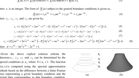
As an example consider the curves shown in Figure 1(a) which define the necessary conditions for solving the PDE given in Equation (1). One should note that the analytic solution scheme defined in Equation (3) is applicable to periodic conditions and therefore in order to solve Equation (1) we restrict the domain of the solution to 0≤ ≤u 1 and 0≤ ≤v 2π which adequately describe the boundary conditions shown in Figure 1(a). Figure 1(b) shows the shape of the surface patch generated by solving Equation (1) subject to the conditions shown in Figure 1(a). It should be noted that the resulting surface shown in Figure 1(b) contains all the curves shown in Figure 1(a) whereby the PDE enables a smooth interpolation of the boundary curves. It is also worth highlighting that the resulting surface patch is solely controlled by the four boundary curves.
(a) (b) Figure 1. PDE surfaces based on boundary curves (a) PDE boundary
curves (b) Resulting PDE smooth surface
III. Facial Representation Using PDE
The most important issue in representing 3D facial information using PDE based surface representation is the allocation of a set of boundary curves that adequately describe the geometry of a human face. Clearly a human face is far more complicated than the surface patch shown in Figure 1. Our approach is based on treating the human face as a set of surface patches (segments) each defined in terms of 4 curves in the 3-space. These curves then serve us as the boundary conditions for solving Equation (1).
whereby we focussed on the main characteristic features of the facial data, such as eyes, nose, and the central region. Having undertaken experimentations with several segmentation approaches, we have eventually adopted an arrangement of boundary curves that adequately represent the face.
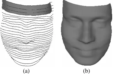
Figure 2 illustrates our approach in defining the boundary conditions for solving Equation (1) to generate a 3D human facial surface. The simplest surface patch is clearly the forehead area, which is represented by four curves in 3-space. These four curves are shown in Figure 2(a), with the resulting PDE surface corresponding to them shown in Figure 2 (b). For a human face, the area belonging to the eyes is more complicated and therefore needed more than four boundary curves in order to ensure the geometry is properly preserved. Similar to the area belonging to the eyes the area belonging to the nose and mouth are equally complicated and therefore require appropriate number of curves to ensure proper geometry is preserved. Thus, our experimentations showed that around 28 cross-section curves across the face are sufficient to generate the surface of a face through the PDE given in Equation (1).
Once the appropriate number of curves is identified, for every two adjacent surface patches (for example, between forehead and eyes) the series of curves are taken together which form the necessary boundary conditions for generating a smooth surface corresponding to the face. In order to ensure that a smooth surface corresponding to the identified curves is generated, we create a single surface patch using multiple calls to the solution of the PDE with the appropriate boundary curves at a given time. For this purpose we define the domain of the parametric region to be such that 0≤ ≤u 9and 0≤ ≤v π. Thus, for the particular case we set uto range from 0 up to 9 since we define the complete face using 9 smoothly connected surface patches.
It is important to note that the above arrangement of boundary profiles (as shown in Figure 2) is a generic representation of 3D facial data in order to enable us to reconstruct a given 3D faces using the solution of the chosen PDE. In addition to this, altering the boundary curves of this generic representation would necessarily produce varying geometries of faces other than the one shown in Figure 2.
(a) (b) Figure 2. Generic facial representation using PDE, (a) represents the PDE boundary curves of facial data, (b) the resulting PDE surface.
In the following section we show the methodology we have implemented in order to enable us to reconstruct a given facial geometry and verify its accuracy based on the PDE formulated described here.
IV. Method of 3D Facial Geometry Reconstruction
3D facial data are usually the output from a 3D scan device after a facial scan and depends on the type of the scanning device the data can be either in the form of a point cloud or a triangular mesh. For the purposes of reading the data into our software platform in a convenient format, we store the data (either point clouds or meshes) in a standard geometry description format known as VRML format which contains information on the location of the data points in the physical space and the connectivity information defined between these points. It is important to highlight that captured facial data can be of any orientation or pose and determination of the orientation and pose of the face in itself of is problem which deserves research merit [24, 25].
As part of the work presented here we have developed a standard software platform environment based on Visual C++ coupled with OpenGL which provided us with a standard user interface. This user interface allows the user to interact with the system and highlight certain facial features, in particular nose tip, inner and outer eyes corners, mouth corners, and the lower and upper part of the facial scan, in order to determine the pose of the face. Using this interactive interface we normalize and align the data in the Cartesian coordinates as shown in Figure 3. A block diagram of the whole process of loading, normalizing, extracting PDE parameters, and reconstructing the facial surface is show in Figure 3.
Figure 3. Block diagram showing the procedures involved in extraction of PDE boundary conditions and reconstruction of facial geometry.
and the width of the central region of the face. Here the width of the central region is determined using the geodesic distance of the cross-section curve that passes through the outer corners of the eyes. For each of such a plane, we identify the set of points from the facial scan that intersects it. Hence using this technique a series of profile curves are automatically extracted from the facial data. Once the curves are extracted, for each curve we then fit a spline of the form Pi=
∑
CiBiwhere Biis acubic polynomial and are the corresponding control points. This process of curve fitting to the extracted discrete curve data enables us to have a smooth curve passing through the discrete data as well as having an equal number of curve points for each profile curve. Figure 4 (a) shows the symmetry profile of a scan image with more than 300 points curve. Figure 4 (b) shows the profile after a spline being fit with 30 points curve which corresponds to a sampling ratio of 10%.
i
C
(a) (b) Figure 4. fitting polynomial splines to have smooth curve and reduce the
size of data (a) extracted symmetry profile from original facial image, (b) spline fitted profile with 10% sampling ratio.
V.
i i
d
=
Experiments and Results
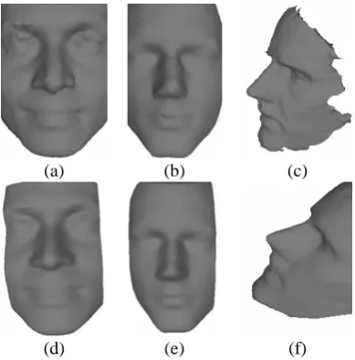
As mentioned above, the approach proposed here has been implemented using C++ coupled with OpenGL and tested using a database of 22 range images of faces acquired by 3D scanners. Facial images range in density ranging between 12,000 vertices, and 51,000 vertices, and therefore the file data size of the model scans varies from 700KB to 1.5 MB. All PDE description of the faces were constructed using the same number of PDE parameters where the resulting boundary curves are only saved to represent a given faces and hence the file size of each of the faces is around 12KB. Several experimentation were carried out, and eventually the adopted approach was based on subjective comparison between original and reconstructed geometry, and also upon the resulting relative error rate between the two models as will be discussed later in this section. Figure 5 shows various facial scans with different densities (a), (b), and (c), while Figure 5 (d), (e), and (f) shows the corresponding reconstructed PDE faces.
(a) (b) (c)
(d) (e) (f) Figure 5. Original facial images and its corresponding reconstructed PDE surface. (a) represents original facial scan and (d) its reconstructed PDE face. (b) represents another facial scan and (e) is its reconstructed PDE face, and similarly (c) is an original facial scan while (f) is its reconstructed PDE facial surface.
In order to evaluate the reconstruction capabilities of the PDE based methodology proposed here we have undertaken experimental and analysis work based on data sampling and determination of relative error rates. In order to do this, we identify appropriate sampling ratios through the PDE curves for facial reconstruction from the original scan data. Clearly using a sampling ratio of 100% implies that the curves to be extracted will be required to contain all the data points within the given region of the original facial data. Thus, for experimental purposes here we have utilized the sampling ratios which range between 5% and 60% of the original data.
To verify the error rates for a sampling ratios we have chosen, we compare the data for both the original mesh and reconstructed PDE surface corresponding to the most static parts of the face namely the central and lateral profiles along the face which are widely used for 3D face recognition [26, 27]. In particular, we have considered the symmetry profile, cross-sectional profile that passes through the eyes and two diagonal profiles that pass through the tip of the nose. The error values represent the difference between the original and reconstructed profiles and were computed as
i n=
1
∑
. Here corresponds to the Euclidean distance between every point on the PDE constructed facial profile and the nearest point to it on the original profile such thati d
( , , )
i i i i
P x y z
( , , )
j j j j P x y z
2 2
( ) ( ) (
i i j i j i j
d = x −x + y −y + z −z )2 . Note that here i ranges from 0..n, such that n is the number of points on the PDE reconstructed profile which is essentially controlled by the number of points on the spline fitted along the extracted profiles.
is shown at Figure 6 (b). Figure 6 (c) shows both symmetry profile of the original facial scan which is represented as a curve drawn as a continuous line, while the symmetry profile of the PDE model is shown as a set
of curve points drawn as ‘x’ symbols. Figure 6 (d) shows the difference between both models symmetry profiles. In Figure 6, the sampling ratio used to sample the curves that represent the PDE parameters is 10%.
Figure 6 Side view of an original facial image, and its corresponding reconstructed PDE image (a) the YZ view of an original 3D facial scan. (b) PDE reconstructed model that corresponds to model at (a), (c) shows the original symmetry profile extracted from model in (a), and represented as a continuous line, while the symmetry profile extracted from the PDE models is presented as a series of points ‘x’ symbols. (d) The error rate between the two symmetry profiles, each value have been multiplied by 103, for visualization purposes.
Table 1 summarizes sampling ratios and the corresponding error rates of the PDE reconstructed models shown in Figure 7. Note that Error rates values here are computed as the average error rate of each facial profile used for comparing faces.
TABLE I. ERRORRATESBASEDONDIFFERENT
SAMPLINGRATIOS
Reconstructing PDE models from original facial scans is done by replacing the boundary curves of the generic template (Figure 2) by the extracted profiles from the original facial data. Clearly the most decisive element is
the number of PDE parameters that control the solution of Equation (1). Figure 7 illustrates the relation between the quality of the reconstructed image, and the sampling ratio used.
(a) (b) (c) (d)
(e) (f) (g) (h)
Figure 7. PDE reconstructed models with different average error rates based on the sampling ratios used. Error rates values of (a)..(h) are shown in Table 1.
Figure Sample Ratio
Number of sampling surface points
Error Rate
Figure 5 (a) 5% 15 7.408 x 10 -3
Figure 5 (b) 10% 30 4.130 x 10 -3
Figure 5 (c) 15% 45 3.070 x 10 -3
Figure 5 (d) 20% 60 2.740 x 10 -3
Figure 5 (e) 25% 75 2.523 x 10 -3
Figure 5 (f) 30% 90 2.330 x 10 -3
Figure 5 (g) 50% 150 1.810 x 10 -3
VI. Conclusion and Future Work
We have successfully demonstrated how PDE based geometry modeling approach could be used to efficiently represent and generate facial geometry of human faces through the use of real data of 3D facial scans. Here it is shown that with minimum input required for reconstruction of a given facial data set is the appropriate PDE boundary curves whereby the topology of the given face is preserved and represented accurately. In our experiments we used range images that vary in size from 700KB to 1.5 MB, and were able to successfully reconstruct the corresponding PDE based geometry of the facial geometry through a series of boundary curves which amount to not more than of 12KB on size. This shows that we can achieve significant saving of 3D geometry file sizes retaining the accuracy of the geometry.
In addition to this, the PDE representation of facial geometry provides users the flexibility in terms of the level of required accuracy of the geometry associated with a particular application. For instance, for certain animation purposes and for 3D faces synthesis facial geometry with probably sampling ratios as in figure 6 (b), and (c) could be used, while for other applications where accuracy matters (i.e. face recognition and authentication) higher sampling rations may be used.
On this theme our next step is to investigate the possibility of using PDE facial geometry for 3D face recognition purposes. In 3D face recognition two main steps are required. i.e. representation of facial data and efficient detection of a given face from a database. We believe that this work has demonstrated us that the first goal of efficient facial representation has already been achieved which will then pave way to the next step of developing an efficient methodology for facial detection. Thus, we aim to build a database of a 3D facial data that is stored as PDE parameters rather than raw facial scan data that will make processing and searching such database more efficient and reliable for both authentication and recognition purposes.
REFERENCES
[1] V. Blanz and T. Vetter, "Face recognition based on fitting a 3D morphable model," Pattern Analysis and Machine
Intelligence, IEEE Transactions on, vol. 25, pp. 1063,
2003.
[2] D. Jiang, Y. Hu, S. Yan, L. Zhang, H. Zhang, and W. Gao, "Efficient 3D reconstruction for face recognition," Pattern
Recognition, vol. 38, pp. 787, 2005.
[3] D. Onofrio and S. Tubaro, "A Model Based Energy Minimization Method for 3D Face Reconstruction," 2005. [4] R. M. Koch, S. H. M. Roth, M. H. Gross, A. P.
Zimmermann, and H. F. Sailer, "A Framework for Facial Surgery Simulation," Budmerice, Slovakia, 2002.
[5] Y. Zhang, E. C. Prakash, and E. Sung, "Face alive,"
Journal of Visual Languages & Computing, vol. 15, pp.
125, 2004.
[6] Y. Lee, D. Terzopoulos, and K. Waters, "Realistic modeling for facial animation," Los Angeles, CA, USA, 1995.
[7] Y. Zhang and N. I. Badier, "Synthesis of 3D faces using region-based morphing under intuitive control,"
COMPUTER ANIMATION AND VIRTUAL WORLDS, vol.
17, pp. 421, 2006.
[8] M. I. G. Bloor and M. J. Wilson, "Generating blend surfaces using partial differential equations," Computer
Aided Design, vol. 21, pp. 165-171, 1989.
[9] T. Goto, W.-S. Lee, and N. Magnenat-Thalmann, "Facial feature extraction for quick 3D face modeling," Signal
Processing: Image Communication, vol. 17, pp. 243, 2002.
[10]W. S. Lee and N. Magnenat-Thalmann, "Fast head modeling for animation," Image and Vision Computing, vol. 18, pp. 355, 2000.
[11]H. H. S. Ip and L. Yin, "Constructing a 3D individualized head model from two orthogonal views," Visual Computer, vol. 12, pp. 254, 1996.
[12]T. Akimoto and Y. Suenaga, "3D facial model creation from front and side views of a face," NTT R&D, vol. 42, pp. 455, 1993.
[13]V. Blanz and T. Vetter, "Morphable model for the synthesis of 3D faces," Proceedings of the ACM
SIGGRAPH Conference on Computer Graphics, pp. 187,
1999.
[14]I. D. Faux and M. J. Pratt, Computational Geometry for
Design and Manufacture: Halsted Press, 1979.
[15] F. Gerald, "From Conics to NURBS: A Tutorial and Survey," IEEE Computer Graphics and Applications, vol. 12, pp. 78-86, 1992.
[16] M. Hoch, G. Fleischmann, and B. Girod, "Modeling and animation of facial expressions based on B-splines,"
Visual Computer, vol. 11, pp. 87, 1994.
[17]Y. Song, L. Bai, and Y. Wang, "3D object modelling for entertainment applications," in Proceedings of the 2006 ACM SIGCHI international conference on Advances in
computer entertainment technology. Hollywood,
California: ACM Press, 2006.
[18]D. Huang and H. Yan, "Modeling and animation of human expressions using NURBS curves based on facial anatomy," Signal Processing: Image Communication, vol. 17, pp. 457, 2002.
[19]M. Eck and H. Hoppe, "Automatic reconstruction of B-spline surfaces of arbitrary topological type," New Orleans, LA, USA, 1996.
[20]H. Du and H. Qin, "A shape design system using volumetric implicit PDEs," Computer-Aided Design, vol. 36, pp. 1101, 2004.
[21][21] J. Monterde and H. Ugail, "A general 4th-order PDE method to generate Bezier surfaces from the boundary,"
Computer Aided Geometric Design, vol. 23, pp. 208, 2006.
[22]H. Ugail, M. I. G. Bloor, and M. J. Wilson, "Manipulation of PDE surfaces using an interactively defined parameterization," Computers and Graphics (Pergamon), vol. 23, pp. 525, 1999.
[23]H. Ugail, M. I. G. Bloor, and M. J. Wilson, "Techniques for interactive design using the PDE method," ACM
Transactions on Graphics, vol. 18, pp. 195, 1999.
[24]S. Malassiotis and M. G. Strintzis, "Real-time head tracking and 3D pose estimation from range data," Barcelona, Spain, 2003.
[25]S. Malassiotis and M. G. Strintzis, "Robust real-time 3D head pose estimation from range data," Pattern
[26]C. Beumier and M. Acheroy, "Automatic 3D face authentication," Image and Vision Computing, vol. 18, pp. 315, 2000.
[27]L. Zhang, A. Razdan, G. Farin, J. Femiani, M. Bae, and C. Lockwood, "3D face authentication and recognition based on bilateral symmetry analysis," Visual Computer, vol. 22, pp. 43, 2006.
Eyad Elyan received his first degree in Compute Science from Al Quds University, Palestine. On 2004 he received his MSc. (hons) degree in software engineering from the University of Bradford, UK. From 2005 until today he is working as a research assistant and a PhD candidate at the EIMC department at the University of Bradford. His research interests include 3D face recognition, pattern recognition, and geometric modeling.