Author for correspondence:
Volume-7 Issue-2
International Journal of Intellectual Advancements
and Research in Engineering Computations
Strengthening of column by using confinement techniques
Mr.S.Gopinathan, Mr.H.Vijayakumar, Mr.A.C.Karthikeyan, Mrs.N.Rajalakshmi
Department of Civil Engineering, Dhanalakshmi Srinivasan Engineering College, Perambalur,
Tamilnadu, India
ABSTRACT
The issue of upgrading the existing civil engineering infrastructure has been one of great importance over a decade. Deterioration of bridge decks, beams, girders and columns, building, parking structures and others may be attributed to ageing, environmentally induced degradation, poor initial design and or construction, lack of maintenance & to accidental events such as earthquakes. Exiting reinforcement concrete columns may require strengthening for a variety of reasons. For example it is likely that the loading on a column might increase over and above the design load, as when a bridge must cater to increased traffic or when a building must be used for purpose other then those for which it was originally designed. In such cases, it may also be necessary to strengthen columns as per new code requirements. Strengthening may also be required because of damage to the structure as a result of environmental degradation. Strengthening of columns represents an engineering problem, involves several solutions each having their own advantages and disadvantages and their own limits to applicability and practicality for instance it is possible to remove deficient columns and construct new ones in their place. Another solution is to place reinforcing steel and form work around a columns and pour additional concrete. Traditionally steel has been used to jacket R.C columns, nut recently fiber reinforced polymer (FRP) has been a viable alternative to steel in some application. Substantial progress has been made over the past decade in the use of composites in the construction industries, which includes the introduction of various confinement techniques that are, it has potential solution to replace or be used to complement conventional steel reinforcement to the problems associated with corrosion and deterioration of the infrastructures.
Keywords:
Strengthening, Jacket R.C columns, Fiber Reinforced Polymer, Steel Reinforcement, CorrosionINTRODUCTION
Strengthening of columns represents an engineering problem, involves several solutions each having their own advantages and disadvantages and their own limits to applicability and practicality for instance it is possible to remove deficient columns and construct new ones in their place. Another solution is to place reinforcing steel and form work around a columns and pour additional concrete. Traditionally steel has been used to jacket R.C columns, but recently fiber reinforced polymer (FRP) has been a viable alternative to steel in some application.
Substantial progress has been made over the past decade in the use of composites in the construction industries, which includes the introduction of various confinement techniques that are, it has potential solution to replace or be used to complement conventional steel reinforcement to the problems associated with corrosion and deterioration of the infrastructures.
An Experimental studies has been taken up to assess the effect of different confinement techniques on RCC short Columns of various parameters like load carrying capacity, load deflection behavior has been studies for determine the efficiency of the confinement.
The experimental results shows that the ultimate behavior of the column is greatly influenced by the type of confinement provided and based on the results of some important conclusion are drawn.
MATERIALS USED
Ordinary Portland cement
Locally available river sand (Fine Aggregate)
Coarse aggregate (max size 20mm)
8 mm, 6mm Diameter bars are used
PVC pipe (2 mm thick)
Weld Mesh (1.5 mm thick) 2 cm spacing b/w
their rods.
Dimensions of the test specimens
A total of 6 columns of 150 mm x 150 mm cross section and 750 mm in height, as depicted in fig were cast. Two columns (CS 1 and CS 2) were control columns with conventional the reinforcement and the remainder (WMS 1 & WMS 2, PVC 1 & PVC 2) had internal confinement of weld mesh and outer confinement of PVC pipe warping. The casting of the columns was done vertically.
Figure: 1 Test Specimens
Casting of ordinary RC column without
confinement
The columns were cast in the vertical position. The reinforcement cage is inserted in to the steel pipe mould. The table vibrator is used to achieve better compaction. The next day the specimens were demoded and subjected to curing for specified number of days. After the specified curing period (28 days) the specimens were taken out for testing.
Casting of weld mesh confinement column
The columns were cast in the vertical position. The reinforcement cage is inserted in to the steel pipe mould along with weld mesh. The weld mesh sheets were arranged in between concrete and reinforcement of the column through out the column length. The next day the specimens were demoulded and subjected to curing for specified number of days. After the specified curing period (28 days) the specimens were taken out for testing.
Casting of RCC column with PVC pipe
wrapping
The columns were cast in the vertical position. The concrete is prepared with M20 mix and properly mixed with mixer machine. The reinforced steel is placed inside the PVC pipes and filled with concrete with regular interval require for compaction. The next day the specimens were demoulded and subjected to curing for specified number of 9 day. After the specified curing period (28 days) the specimens were taken out for testing
Curring of test specimen
The test specimens were de mound after 24 hours of casting. The remold specimens were immersed in the curing tank and stored in place free from vibration and at a temperature of 270C. The moulds were allowed to cure of 28 days.
METHOD OF TESTING
Copyrights © International Journal of Intellectual Advancements and Research in Engineering Computations,
machine of load was applied gradually, during testing, formation and growth of crack were recorded on the column by drawing line along the crack and marking the corresponding loads, while taking readings, extreme care was taken not to touch any of the testing & measuring equipment.
TESTING PROCEDURE
The specimens were placed on the Universal testing machine. The dial gauges were placed on the middle of the column. Deflection readings were taken with the help of dial gauge. Load was applied on the specimen gradually. Deflections were noted at predetermined load levels. The load was applied continuously till the failure of the
specimen takes place the type of failure was noted down carefully.
The compression load was gradually applied on the specimen till the final failure of the specimen taken place. The dial gauges which are used for measuring the lateral deflection were measured at the time of ultimate loads.
TEST SET UP
The columns specimens cast by using various external confinements that are weld mesh and PVC pipe warping were tested for its load carrying capacity of the different types of column. Before the testing column dial gauge were placed along the height of the column, dial gauge were rest on the opposite side and placed middle column.
Figure: 2 Test setup for RC column
TEST RESULT
Table:1 load carrying capacity of ordinary RC column-1
SI.
No. Load (kN)
Lateral Deflection (mm)
1 0 0
2 20 0.02
3 40 0.03
4 60 0.035
5 80 0.04
6 100 0.058
7 120 0.085
8 140 0.105
9 160 1.10
11 200 1.25
12 220 1.30
Table 2 Load Carrying Capacity of ordinary RC column-2
SI.
No. Load (kN)
Lateral Deflection (mm)
1 0 0
1 20 0.015
2 40 0.03
3 60 0.038
4 80 0.05
5 100 0.125
6 120 0.215
7 140 0.37
8 160 0.54
9 180 0.72
10 200 1.02
11 220 2.15
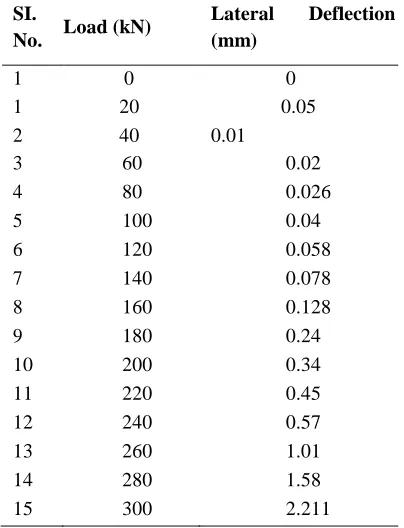
Table 3 Load Carrying Capacity of Weld Mesh specimen- 1
SI.
No. Load (kN)
Lateral Deflection (mm)
1 0 0 1 20 0.05 2 40 0.01
3 60 0.02
4 80 0.026
5 100 0.04
6 120 0.058
7 140 0.078
8 160 0.128
9 180 0.24
10 200 0.34
11 220 0.45
12 240 0.57
13 260 1.01
14 280 1.58
15 300 2.211
Table 4 Load Carrying Capacity of Weld Mesh specimen-2
SI.
No. Load (kN)
Lateral Deflection (mm)
Copyrights © International Journal of Intellectual Advancements and Research in Engineering Computations,
1 20 0.018
2 40 0.017
3 60 0.192
4 80 0.198
5 100 0.195
6 120 0.191
7 140 0.245
8 160 0.265
9 180 0.275
10 200 0.460
11 220 0.335
12 240 0.645
13 260 0.845
14 280 1.246
15 300 2.146
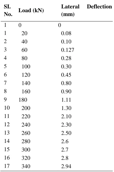
Table 5 Load Carrying Capacity of PVC specimen-1
SI.
No. Load (kN)
Lateral Deflection (mm)
1 0 0
1 20 0.08
2 40 0.10
3 60 0.127
4 80 0.28
5 100 0.30
6 120 0.45
7 140 0.80
8 160 0.90
9 180 1.11
10 200 1.30
11 220 2.10
12 240 2.30
13 260 2.50
14 280 2.6
15 300 2.7
16 320 2.8
17 340 2.94
Table 6 Load Carrying Capacity of PVC specimen-2
SI.
No. Load (kN)
Lateral Deflection (mm)
1 0 0
1 20 0.02
3 60 0.03
4 80 0.032
5 100 1.138
6 120 1.150
7 140 1.180
8 160 1.182
9 180 1.182
10 200 1.90
11 220 1.92
12 240 2.01
13 260 2.20
14 280 2.40
15 300 2.55
16 320 2.65
17 340 2.78
MODE OF FAILURE OF CONTROL
SPECIMEN
The loading was applied gradually till the failure of specimen the first crack has been formed also the load level of 120 KN at the time of lateral deflection was noted as 0.085 mm. The loading
was continued and the ultimate levels recorded 220 KN. The failure of all specimens was due to conducted of concrete at the top and bottom of all specimens. Figures show the failure of RC column specimen without confinement.
Figure: 3 Failure of ordinary RC column
Mode of failure of weld mesh confinement of
column
The loading was applied gradually till the failure of specimen the first crack has been formed also the load level of 200kN at the time of lateral deflection was noted as 0.34 mm. The loading was
Copyrights © International Journal of Intellectual Advancements and Research in Engineering Computations, Figure: 4 Failure of weld mesh confinement
Mode of failure of PVC pipe confinement of
column
The loading was applied gradually till the failure of specimen. The first crack has been formed also the load level of 220KN at the time of lateral deflection was noted as 1.92mm. The
loading was continuing and the ultimate levels recorded as 340 KN. The failure of all specimens was due to conducted of concrete at the top and bottom of all specimens. A figure shows the failure of RC column with PVC confinement.
Figure: 5 Failure of PVC confinement
COMPARISON OF TEST RESULTS
Load carrying capacity
From Table it is evident that the weld confinement used for columns were found to with stand a maximum load of 300 kN in compression. This is better than the reference RC columns or
control specimen which took a maximum load of 220 kN. PVC pipe warping confinement used for RC columns was found to with stand a maximum load of 340 kN in compression. This is better than the reference weld mesh confined RC columns which took a maximum load of 300 kN.
Table 7 Ultimate load for RC Columns
Type of columns
Control 1 specimen
RC column confined with weld mesh
RC column confined with PRC pipe warping
Ultimate Load (KN)
Load deflection behavior
The Lateral deflection value for the PVC confinement RC column were around 2.94 for a maximum load of 340 KN. The lateral deflection was found to be more or les constant above 120 KN of ordinary control specimen underwent a maximum lateral deflection of 2.15 mm at ultimate load 220 KN. The Lateral deflection for constant of 120 KN PVC confinement RC column were found to have deflection of 145 which was less than ordinary RC column as well as weld mesh confinement the lateral Deflection for weld mesh confinement RC column were around 0-191 for a
load of 120 KN which was less than ordinary RC columns. Generally, the ordinary RC columns were found to deflect more than the confinement column at the constant load of 120 KN.
Cracking behavior of RC columns
The different confinement types of RC column in addition with concrete may affect the first cracking load capacity of the columns. The comparison or ultimate load capacity of the columns. The comparison of ultimate load and initial crack loads of various types of RC columns is given in Table.
Table:8 Comparison of ultimate and initial crack loads
Type of columns
Control Specimen
Weld mesh confinement RC
columns
PVC pipe warping RC Column
Ultimate Load (KN)
220 300 340
Initial Crack Load (KN)
120 160 200
Behaviour and mode of failure
All the columns were subjected to axial compression. The columns withstand up to the ultimate load and fails by crushing of concrete. The ultimate failure of ordinary RC column as the load of 220 kN at that time of maximum deflection is 2.15mm, the ultimate failure of PVC
confinement of RC column as the load of 340 kN at the time of maximum deflection as 2.146mm and weld mesh confinement of RC column as the load of 300 kN at that time of maximum deflection as 2.94mm when the ultimate failure of the specimen was due to the crushing of concrete at top & bottom ends of the all specimens.
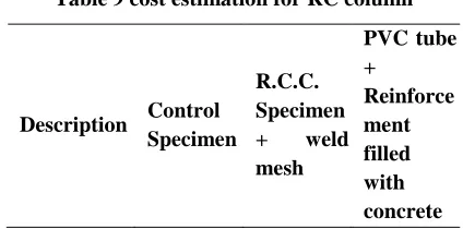
COST ESTIMATION
Table 9 cost estimation for RC column
Description Control Specimen
R.C.C. Specimen + weld mesh
PVC tube +
Copyrights © International Journal of Intellectual Advancements and Research in Engineering Computations,
Rate 182 207 267
% Increase - 14% 47%
CONCLUSION
An experimental investigation has been carried out study the behavior of RC column load carrying capacity & cost for with and without confinement. Based on the experimental study the following conclusion are drawn,
By un confined conventional R.C. circular column + inner layer of weld mesh with load
carrying capacity is increased by 36% and rate increased 14% of ordinary RC column.
By unconfined conventional R.C. Circular column + outer layer of PVC confined wrapping the load carrying capacity increased by 54.5% and rate increased
47% of
ordinary RC column.
By confined R.C.C circular column with PVC wrapping the load carrying capacity is
increased by 13.3% and rate increased
33% of confined weld mesh column.
REFERENCES
[1]. B. Vijaya Rangan “Strength of Reinforcement concrete slender column” ACI structural Journal, 81(1), 1990, 32-38.
[2]. Anonymous IS 456-2000 “Indian Standard Code of Practice For Plain And Reinforcement Concrete” (Fourth revision) Indian Standard Institution, New Delhi. 1993
[3]. U.Sharma (S.L., NIIT, HP), P. Bhargava (A.P., IIT Roorkela), S.K. Kaushik (Prop, IIT Roorkee) “Evaluation of confinement reinforcement requirements of IS 13920: 1993 for RC column” The Indian Concrete Journal, 2005, 51-59.
[4]. Mac Gregor, James G., Breen, John E., and Pfang, Edward “Design of Slender Column”, ACI Structural Journal, Proceeding, 67(1), 1970, 628.
[5]. S.K. Duley (S.L.) & Dr. S.V. Deodhar (Director), B.S. Deore, college of Engineer ing, Dhule “Studies on Concrete infilld PVC pipes with core PVC” Journal of NBM & CW 2005, 82-84.
[6]. V.Nagarad jane “ANN model for the effect of slenderness on concentrically loaded concrete cylinders confined by GFRP” The Indian concrete journal, 2007.
[7]. M.S.R.Kumutha “Fibre wrapping technology to strengthened R.C Circular columns” NBM & CW, 2006. [8]. M.S.R.Kumutha “Fibre wrapping technology to strengthened R.C Circular columns” NBM & CW 2005. [9]. Vishwanath K.G “An experimental investigation on short columns reinforced with micro & macro fibres”
NBM & CW 2005.