http://www.sciencepublishinggroup.com/j/ajop doi: 10.11648/j.ajop.20190704.11
ISSN: 2330-8486 (Print); ISSN: 2330-8494 (Online)
Image Registration Method Based on Optimized SURF
Algorithm
Zhang Sheng
1, 2, 3, 4, *, Li Peihua
1, 2, 3, 4, Liu Yuli
1, 2, 3, 4, Qian Mingsi
1, 2, 3, 4, Ji Changgang
1, 2, 3, 4,
Zhou Meng
1, 2, 3, 41
Avic Huadong Photoelectric Company Limited, Wuhu, China
2State Special Display Engineering Laboratory, Wuhu, China 3National Special Display Engineering Research Center, Wuhu, China 4
Anhui Province Key Laboratory for Modern Display Technology, Wuhu, China
Email address:
*
Corresponding author
To cite this article:
Zhang Sheng, Li Peihua, Liu Yuli, Qian Mingsi, Ji Changgang, Zhou Meng. Image Registration Method Based on Optimized SURF Algorithm. American Journal of Optics and Photonics. Vol. 7, No. 4, 2019, pp. 63-69. doi: 10.11648/j.ajop.20190704.11
Received: November 17, 2019; Accepted: December 6, 2019; Published: December 18, 2019
Abstract:
In order to solve the time consuming problem of image registration based on the traditional SURF algorithm, the image registration method based on the optimized SURF algorithm is proposed. Firstly, the image corner points are extracted by the Shi-Tomasi algorithm, then, the SURF algorithm is used to generate the corner point descriptors and the sparse principle algorithm is used to reduce the dimension of the corner point descriptors. Finally, the bidirectional matching algorithm is used to match. Through the experimental data analysis, the image registration method based on the optimized SURF algorithm is nearly the same in image registration accuracy in comparison with the traditional SIFT algorithm, the traditional SURF algorithm and the other four optimized algorithms, but the time consuming of image registration is decreased by 79.09%, 47.74%, 66.25%, 50.79%, 21.43% and 5.13%, respectively, verifying the instantaneity and effectiveness of the algorithm.Keywords:
SURF Algorithm, Shi-Tomasi Algorithm, Sparse Principle Algorithm, Bidirectional Matching Algorithm, Image Registration1. Introduction
Image registration methods are widely used in the fields of medical image processing, remote sensing image processing and panoramic stitching [1-3]. Among them, the SURF (Speed-Up Robust Features) algorithm [4] was proposed by Herbert Bay et al. in 2006, which is one of the most commonly used algorithms in image registration. In order to solve the time consuming problem of image registration based on the traditional SURF algorithm, many optimization algorithms had been proposed by domestic surgical researchers in recent years. Firstly, aiming at the time consuming problem of image features extraction based on the traditional SURF algorithm. In 2014, Ge Panpan et al. proposed to use the Harris algorithm [20] to replace the image features extraction part of the SURF algorithm, which shortens the image feature extraction time and ensures the
Zhang Ni et al. proposed to use the compressed sensing algorithm and the random sampling consistency algorithm [11] to reduce the time of image registration. In 2018, Lu Pingping et al. proposed to use the PCA (principle component analysis) algorithm [12] to reduce the dimension of the image feature descriptors, which achieves the purpose of reducing image features matching time [13]. In order to solve the time consuming problem of image registration based on the traditional SURF algorithm, this paper uses the Shi-Tomasi algorithm [14], the sparse principle algorithm [15] and the bidirectional matching algorithm to optimize the traditional SURF algorithm. The result is that the accuracy of image registration is equivalent and shorten the time of image registration, namely the Shi-Tomasi-CS-SURF algorithm.
2. Shi-Tomasi-CS-SURF Algorithm
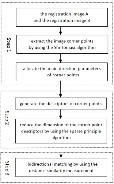
The traditional SURF algorithm is divided into three stages according to the implementation process, the first stage is to extract the image features and allocate the main direction parameters, the second stage is to use the main direction parameters of the image features to generate the image feature descriptions, the third stage is to use the matching algorithm to match image features. In this paper, the first stage of the SURF algorithm is optimized by using the Shi-Tomasi algorithm, the second stage of the SURF algorithm is optimized by using the sparse principle algorithm, and the third stage of the SURF algorithm is optimized by using the bidirectional matching algorithm. The flow chart of the Shi-Tomasi-CS-SURF algorithm is shown in Figure 1.
Figure 1. The flow chart of the Shi-Tomasi-CS-SURF algorithm.
2.1. Corner Extraction
The Shi-Tomasi algorithm [14]was proposed by Shi and Tomasi in 1994. Among all kinds of the corner point extraction algorithms, the Shi-Tomasi algorithm has the same stability as the Harris algorithm, and it is not easy to be affected by image rotation, illumination conditions, angle changes and noise, which can also avoid corner points clustering. This paper uses the Shi-Tomasi algorithm to extract the image corner points.
The implementation steps of the Shi-Tomasi algorithm: Step 1: Calculate the Ix and Iy of each pixel on the image I, as shown in formula (1) and (2):
( 2, 1, 0,1, 2) x
I = ⊗ − −g (1)
( 2, 1, 0,1, 2)T y
I = ⊗ − −g (2)
Where: Ix represents the gradient of the image I in X direction, Iy represents the gradient of the image I in Y direction, g represents the registration image and ⊗ represents the convolution operation.
Step 2: Calculate the Ix2, Iy2 and Ixy by using the Ix and Iy, as shown in formula (3), (4) and (5):
(
)
2
x x x
I = I ×I ⊗w (3)
(
)
xy x y
I = I ×I ⊗w (4)
(
)
2
y y y
I = I ×I ⊗w (5)
Where: Ix represents the gradient of the image I in X direction, Iy represents the gradient of the image I in Y direction, g represents the registration image,⊗ represents the convolution operation and w represents the Gaussian function.
Step 3: Calculate the autocorrelation matrix M by using the Ix2, Iy2 and Ixy, as shown in formula (6):
2
2
M x x y
x y y I I I
I I I
=
(6)
Where: M represents the autocorrelation matrix, Ix represents the gradient of the image I in X direction, Iy represents the gradient of the image I in Y direction.
Step 4: Calculate the corner point response value, as shown in formula (7):
1 2
min( )
R= λ λ (7)
Where: R represents the corner point response value, λ1 and λ2 represent two eigenvalues of the autocorrelation matrix M.
Step 5: Set the threshold value Th, if R is greater than Th, then it is a candidate corner point, otherwise it is not a candidate corner point.
window is 3×3 or 5×5. If the corner point response value is the local maximum value, the pixel is considered as the corner point feature.
2.2. Corner Point Description and Sparse Principle
Aiming at the corner points are extracted in Section 2.1, the SURF algorithm is used to allocate the main direction parameters, then the main direction parameters of the corner points are used to generate the 64-dimension corner point descriptors. Finally, the 64-dimension corner point descriptors are assumed to be K, and the 64-dimension corner point descriptors are reduced to the 24-dimension measurement vectors by using the wavelet transform basis matrix Ψand the 24 64× dimensions random projection matrix R∈R24 64× . The 24-dimension measurement vectors are used as the corner point descriptors, as shown in formula (8):
K′ =RY= ΨR K (8) Where: K′ represents the 24-dimension measurement vectors, R represents the random projection matrix of 24 64× dimensions, Y represents the 64-dimension sparse vector, Ψ represents the wavelet transform matrix of 64 64× dimensions, and K represents the 64-dimension corner point descriptors.
2.3. Bidirectional Matching
Assuming that the reference image and the registration image are image registration pairs, aiming at the 24-dimension corner point descriptors in Section 2.2, set the corner point descriptors in the reference image as
i 1 2 3 22 23 24
U (x ,x ,x ,……,x ,x ,x ), and set the corner point descriptors in the registration image as
j 1 2 3 22 23 24
V (y ,y ,y ,……,y ,y ,y ) , then the similarity measurement equation of corner points between the reference image and the registration image is as shown in formula (9):
24
1
d( i, j) m m m
U V x y
=
=
∑
− (9)Where:xm represents the element of the corner point description in the reference image, ym represents the element of the corner point description in the registration image, and d(U Vi, j) represents the similarity measure
value of corner points between the reference image and the registration image.
In this paper, the similarity measure algorithm is used for bidirectional matching. Firstly, the corner points set in the reference image is assumed to be U , and the corner points set in the registration image is assumed to be V . Then, taking the corner point Ui in the corner points set U as the object, the formula (9) is used to traverse the all corner points in the corner points set V , which gets the minimum value of d and the sub minimum value of d , namely the nearest neighbor corner point and the sub nearest neighbor corner
point. If the minimum value of d and the sub minimum value of d are satisfied with formula (10), the corner point
1j
V in the corner points set V and the corner point Ui in
the corner points set U are a pair of matching corner points, traversing all corner points in the corner points set U to get all the matching corner point pairs set A. Then, taking the corner points set V as the object, using formula (9) and (10) to find the matching corner point in the corner points set U, which to get the matching corner point pairs set B. Finally, if the matching corner point pairs of set A and the matching corner point pairs of set B are identical, they are the effective matching corner point pairs, the effective matching corner point pairs set is the final matching corner point pairs set.
(
)
(
i 1)
hi 2
d U ,
d U , j
j V
T
V < (10)
Where: d U ,
(
i V1j)
represents the similarity measurevalue between the corner point Ui in the corner points set Uand the nearest neighbor corner point V1j in the corner
points set V ,d U ,
(
i V2j)
represents the similarity measurevalue between the corner point Ui in the corner points set U and the next nearest neighbor corner point V2jin the
corner points set V , and Th represents the threshold value. In this paper, the threshold value is set as 0.8.
3. Experimental Results
The experimental programming hardware platform is the computer, which uses Intel Core i3-3240 CPU @ 3.40GHz four cores, the memory is 4G and the operating system is 32-bit Windows 7.
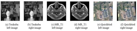
In this paper, the Tsukuba images in the Stereo Matching database, the Mr_T1 brain medical images in the Normal Brain database and the remote sensing images of Beijing are taken by the QuickBird satellite in 2015 are used as experimental images. Figure 2 (a)~(b) represent the left Tsukuba image and the right Tsukuba image with different perspectives in Stereo Matching database, with the size of 384×288 pixels. Figure 2 (c)~(d) represent the deformed Mr_T1 brain medical images in the Normal Brain database, with the size of 250×190 pixels. Figure 2 (e)~(f) represent the deformed remote sensing images of Beijing are taken by the QuickBird satellite in 2015, with the size of 181×217 pixels.
Figure 2. The experimental images of image registration.
the reference [17] algorithm, the reference [18] algorithm, the reference [19] algorithm and the image registration method based on the optimized SURF algorithm to carry out the image registration experiment on the experimental registration images. The image registration results are shown in Figure 3 (a)-(u). At the same time, in order to determine the efficiency between the the traditional SIFT algorithm, the traditional SURF algorithm, the reference [16] algorithm, the reference [17] algorithm, the reference [18] algorithm, the reference [19] algorithm and the image registration method based on the optimized SURF algorithm, this paper selects six indicators as the evaluation standard datas, that are the number of image corner points, the number of image corner point matching pairs, the number of correct image corner point matching pairs, the image registration accuracy, the image registration time and the decline rate of the image registration time, the image registration accuracy and the decline rate of the image registration time are shown in formula (11) and (12), and the quantitative analysis diagrams of image registration are shown
in figure 4 (a)-(d). According to figure 4 (b), compared with the traditional SIFT algorithm, the traditional SURF algorithm, the reference [16] algorithm, the reference [17] algorithm, the reference [18] algorithm and the reference [19] algorithm, the image registration accuracy of the image registration method based on the optimized SURF algorithm is equivalent. According to figure 4 (d), compared with the traditional SIFT algorithm, the traditional SURF algorithm, the reference [16] algorithm, the reference [17] algorithm, the reference [18] algorithm and the reference [19] algorithm, the image registration time of the image registration method based on the optimized SURF algorithm is decreased by 77.54%, 57.65%, 64.67%, 65.60%, 34.15% and 24.16%, respectively.
correct matching logarithm image regi
ma stration
tching logarithm
NUM
NUM
R = (11)
optimization algorithm time reducti
traditional algorithm
traditional algorithm on
R T T
T
−
= (12)
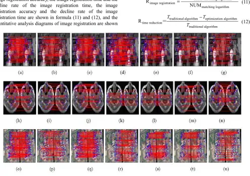
Figure 3. The result images of image registration.
Figure 3 (a)-(g) respectively represent the image registration results of Figure 2 (a) and Figure 2 (b) by using the traditional SIFT algorithm, the traditional SURF algorithm, the reference [16] algorithm, the reference [17] algorithm, the reference [18] algorithm, the reference [19] algorithm and the image registration method based on the optimized SURF algorithm. Figure 3 (h)-(n) respectively represent the image registration results of Figure 2 (c) and Figure 2 (d) by using the traditional SIFT algorithm, the traditional SURF algorithm, the reference [16] algorithm, the
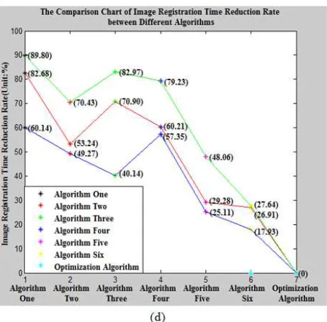
Figure 4. The quantitative analysis diagrams of image registration.
Figure 4 (a) shows the vertical bar graph of the number of corner points, corner point matching pairs and correct corner point matching pairs by using the traditional SIFT algorithm, the traditional SURF algorithm, the reference [16] algorithm, the reference [17] algorithm, the reference [18] algorithm, the reference [19] algorithm and the image registration method based on the optimized SURF algorithm. Figure 4 (b) shows the curve diagram of the image registration accuracy by using the traditional SIFT algorithm, the traditional SURF algorithm, the reference [16] algorithm, the reference [17] algorithm, the reference [18] algorithm, the reference [19] algorithm and the image registration method based on the optimized SURF algorithm. Figure 4 (c) shows the curve diagram of the image registration time by using the traditional SIFT algorithm, the traditional SURF algorithm, the reference [16] algorithm, the reference [17] algorithm, the reference [18] algorithm, the reference [19] algorithm and the image registration method based on the optimized SURF algorithm. Figure 4 (d) shows the curve diagram of the decline rate of the image registration time by using the traditional SIFT algorithm, the traditional SURF algorithm, the reference [16] algorithm, the reference [17] algorithm, the reference [18] algorithm, the reference [19]
algorithm and the image registration method based on the optimized SURF algorithm.
In order to verify the time and accuracy of the image registration method based on the optimized SURF algorithm, 100, 200, 300 and 400 pairs of image registration respectively are selected as experimental subsets from a set of 400 pairs of image registration. For the traditional SIFT algorithm, the traditional SURF algorithm, the reference [16] algorithm, the reference [17] algorithm, the reference [18] algorithm, the reference [19] algorithm and the image registration method based on the optimized SURF algorithm, the image registration time and the image registration accuracy are counted, the experimental data are shown in Table 1. According to the experimental data in Table 1, compared with the traditional SIFT algorithm, the traditional SURF algorithm, the reference [16] algorithm, the reference [17] algorithm, the reference [18] algorithm and the reference [19] algorithm, the image registration accuracy of the image registration method based on the optimized SURF algorithm is equivalent, but the image registration time is reduced by 79.09%, 47.74%, 66.25%, 50.79%, 21.43% and 5.13%, respectively.
Table 1. The comparison table of the image registration time and accuracy of the different scale image sets.
Algor.ithm/ Parameter
100 200 300 400
t/(s) Accuracy / (%) t/(s) Accuracy / (%) t/(s) Accuracy / (%) t/(s) Accuracy / (%) Algorithm One 4264.3 94.24 8020.6 96.10 13452.8 95.87 17502.6 96.56
Algorithm Two 1694.3 95.63 3502.9 95.46 5345.2 96.39 7002.6 96.19 Algorithm Three 2793.6 95.35 5623.8 95.99 8345.3 96.32 10845.3 96.49 Algorithm Four 1826.9 95.65 3815.6 95.78 5546.3 95.32 7436.8 96.11 Algorithm Five 1126.5 95.01 2500.3 96.32 3400.5 96.33 4658.3 95.87 Algorithm Six 987.6 96.16 2003.5 96.16 2986.3 96.55 3857.9 97.01 Optimization
Algorithm 908.9 96.02 1840.6 96.10 2766.3 96.22 3659.9 96.87
Among them, Algorithm One represents the traditional SIFT algorithm, Algorithm Two represents the traditional SURF algorithm, Algorithm Three represents the reference
algorithm, Optimization Algorithm represents the image registration method based on the optimized SURF algorithm, time represents the image registration time, accuracy represents the image registration accuracy.
4. Conclusions
Based on the traditional SURF algorithm, this paper optimizes it by using the Shi-Tomasi algorithm, the sparse principle algorithm and the bidirectional matching algorithm, namely the image registration method based on the optimized SURF algorithm, also namely Shi-Tomasi-CS-SURF algorithm. Compared with the traditional SIFT algorithm, the traditional SURF algorithm, the reference [16] algorithm, the reference [17] algorithm, the reference [18] algorithm and the reference [19] algorithm, the Shi-Tomasi-CS-SURF algorithm has obvious advantages in the time consuming aspect of image registration. At the same time, the algorithm is verified to be practical through the image registration pairs set.
Acknowledgements
We are grateful for research funding and support from: AVIC Huadong Photoelectric Company Limited and the Fire Helmet Project of Wuhu Science and Technology Bureau.
References
[1] Zhang Li, Li Bin, Tian Lianfang, et al. Medical image registration based on Log-Euclidean covariance matrices descriptor. Chinese Journal of Computers, 2019, 42 (9): p. 2087-2099.
[2] He Mengmeng, Guo Qing, Li An, et al. Automatic fast feature-level image registration for high-resolution remote sensing images. Journal of Remote Sensing, 2018, 22 (2): p. 277-292.
[3] Zhu Jihua, Zhou Yi, Wang Xiaochun, et al. Grid map merging approach based on image registration. Acta Automatica Sinica, 2015, 41 (2): p. 285-294.
[4] Bay H, Tuytelaars T, Gool L V. SURF: Speeded Up Robust Features. Proceedings of the European Conference on Computer Vision, 2006: p. 404-417.
[5] Ge Panpan, Chen Qiang, Gu Yihe. Algorithm of remote sensing image matching based on Harris corner and SURF feature. Application Research of Computers, 2014, 31 (7): p. 2205-2208.
[6] Rosten E, Drummond T. Machine Learning for High-Speed Corner Detection. International European Conference on Computer Vision, 2006: p. 430-443.
[7] Chen Jianhong, Han Xiaozhen. Image matching algorithm combining FAST-SURF and improved k-d tree nearest
neighbor search. Journal of Xi’an University of Technology, 2016, 32 (2): p. 213-217.
[8] Trajkovic M, Hedley M. Fast Corner Detection. Image and Vision Computing, 1998, 16: p. 75-87.
[9] Yang Sa, Yang Chunling. Image registration algorithm based on sparse random projection and scale-invariant feature transform. Acta Optica Sinica, 2014, 34 (11): p. 1110001s-1-1110001-5.
[10] Zhao Aigang, Wang Hongli, Yang Xiaogang, et al.. Compressed sense SIFT descriptor mixed with geometrical feature. Infrared and Laser Engineering, 2015, 44 (3): p. 1085- 1091.
[11] Zhang Ni, Zhang Chengcheng, He Xiongxiong. Fast SIFT quasi-dense matching algorithm based on compressive sensing. Journal of ZheJiang University of Technology, 2017, 45(3): p. 310-314.
[12] Jolliffe I T. Principal Component Analysis. New York: Springer-Verlag New York Inc, 2002.
[13] Lu Pingping, Mei Xue. Aerial image stitching registration algorithm for UAV based on dimensionality reduction and clustering. Computer Applications and Software, 2018, 35 (6): p. 220-225.
[14] Shi J, Tomasi C. Good feature to track. Computer Vision & Pattern Recognition, 1994, 84 (9): p. 593-600.
[15] Liu Fang, Wu Jiao, Yang Shuyuan, et al.. Research advances on structured compressive sensing. Acta Automatica Sinica, 2013, 39 (12): p. 1980-1995.
[16] Liu Hui, Shen Hailong. Image match method based on improved SIFT algorithm. Microelectronics and Computer, 2014, 31 (1): p. 38-42.
[17] Xu Jiajia, Zhang Ye, Zhang He. Fast image registration algorithm based on improved Harris-SIFT descriptor. Journal of Electronic Measurement and Instrumentation, 2015, 29 (1): p. 48-54.
[18] Han Chao, Fang Lu, Zhang Sheng. An optimized image registration algorithm. Journal of Electronic Measurement and Instrumentation, 2017, 31 (2): p. 178-184.
[19] Zhang Sheng, Li Peihua, Zhang Jun, et al.. Research on image registration algorithm based on compressed sensing. Optoelectronic Technology, 2018, 38 (2): p. 111-116.
[20] Harris C, Stephens M. A combined corner and edge detector. Proceedings of the Fourth Alvey Vision Conference, 1988: p. 147-151.
[21] Lowe D G. Object recognition from local scale-invariant features. Proceedings of the International Conference on Computer Vision, 1999: p. 1150-1157.