NI Labview Fundamentals (2005)
Full text
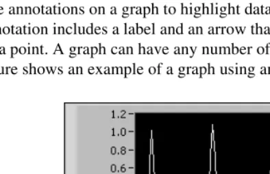
Figure

Related documents
Patients suffering from acute myocardial infarction with ST elevation (STEMI ACS) ( initiated from a few days after the event until less than 35 days ), ischaemic cerebral
Participation in the BIP program will reinforce our ongoing efforts to improve access to home and community based long term care services for those with physical, behavioral
While we find a substantial impact of the new compulsory schooling policy on the time until marriage and first-birth for teenage women in Turkey, we find no evidence
In string sets with thinner strings (“light gauge strings”), the three treble strings are solid (“plain”) while the heavier strings are wound; in heavier gauge string sets,
Thus, for a debtor to obtain modification of a mortgage holder’s right, as noted by Judge Grossman of this court, “Section 1322(b) specifies that the modification must take place in
Getting Started with .Net Framework, Exploring Visual Studio .NET, Inside a C# Program, Data Types, Statements, Arrays, Using Strings, Objects, Classes and
• Business appraisal (BA) - where a detailed cost benefit analysis is undertaken on schemes that have been identified as having potential for investment before the scheme
Observed numbers of Aedes pupae per with estimated transmission threshold (extrapolated from Table 9.1) based on hottest mean temperatures and seroprevalence of 33%
