*Corresponding author: Abdul Baais Akhoon ISSN: 0976-3031
Research Article
EVALUATION OF INTER-RADICULAR SPACES AND CORTICAL BONE THICKNESS AT COMMON
ORTHODONTIC MINI-SCREW IMPLANT PLACEMENT SITES USING CONE BEAM COMPUTED
TOMOGRAPHY
Abdul Baais Akhoon and Mohammad Mushtaq
Department of Orthodontics and Dentofacial Orthopaedics, Govt. Dental College and Hospital,
Srinagar, J & K, India
DOI: http://dx.doi.org/10.24327/ijrsr.2017.0812.1291
ARTICLE INFO ABSTRACT
Miniscrews have been extensively used in orthodontics in the last few years for obtaining absolute orthodontic skeletal anchorage. Many studies have been found in literature addressing the subject. However, there is still no consensus in these studies about the factors that influence the success of miniscrew implants. The aim of this article is to provide an anatomical map for safe placement of miniscrews in maxilla and mandible and palatal region, based on dimensional mapping of the inter-radicular spaces and cortical bone thickness.
CBCT images of 47 pre-treatment Kashmiri orthodontic patients were examined. Measurements were made from the distal aspect of the lateral incisor to the mesial aspect of the second molar of maxilla and mandible, at 2, 5, 8, and 11 mm heights from the alveolar crest in each inter-radicular area. Palatal bone thickness was measured at 4, 8, 16 and 24 mm from the incisive foramen at the suture and at 3 and 6 mm paramedian to the suture.
In the maxilla, the greatest mesiodistal distance was between second premolar and first molar at 11 mm height. The greatest buccolingual alveolar process width and buccal cortical bone thickness were between first and second molar at 11 mm height. The greatest palatal bone thickness was at 4 mm posterior to incisive foramen and 6 mm lateral to the suture. In the mandible, the greatest mesiodistal distance and buccal cortical thickness was between first and second molar at 11 mm height. The greatest buccolingual alveolar process width was between first and second molar at 8 mm height.
In the maxilla, the safe and suitable site for placing miniscrew implant was between the second premolar and first molar. In the mandible, the safe and suitable sites are the inter-radicular areas between first and second molar.
INTRODUCTION
To achieve excellent results during orthodontic treatment, adequate control of anchorage is necessary (Papadopoulos and Tarawneh, 2007). The patients with bimaxillary dentoalveolar protrusion demonstrated protrusive and proclined upper and lower incisors and an increased procumbency of the lips. The primary goals of orthodontic treatment of these patients include retraction and retroclination of maxillary and mandibular incisors with a resultant decrease in soft tissue procumbency and convexity. This is most commonly achieved by orthodontic treatment in combination with extraction of four first premolars, and retraction of anterior teeth using maximum anchorage mechanics (Bills et al, 2005). Recently, the use of miniscrew implants to obtain absolute anchorage has become
very popular, because of the small size, uncomplicated surgical procedure, immediate load, lower medical cost, minimal patient cooperation, and multiple insertion positions (Papadopoulos and Tarawneh, 2007; Park et al, 2001; Chung et al 2007). The buccal inter-radicular area is commonly selected for miniscrew implant placement (Fayed et al 2010; Baumgaertel and Hans, 2009). This area is not only easy for miniscrew implant placement, but also allows relatively simple orthodontic mechanics (Farnsworth et al, 2011; Chaimanee et al, 2011). Two factors that clinicians should consider during miniscrew implant placement are safety and stability. Safety is related to avoiding anatomical damage during miniscrew implant placement or when teeth are displaced (Papadopoulos and Tarawneh, 2007; Park and Cho, 2009). The insertion of a miniscrew implant in this buccal inter-adicular area carries a
Recent Scientific
Research
International Journal of Recent Scientific Research
Vol. 8, Issue, 12, pp. 22565-22570, December, 2017
Copyright © Abdul Baais Akhoon and Mohammad Mushtaq, 2017, this is an open-access article distributed under the terms of the Creative Commons Attribution License, which permits unrestricted use, distribution and reproduction in any medium, provided the original work is properly cited.
DOI: 10.24327/IJRSR
CODEN: IJRSFP (USA)
Article History:
Received 10th September, 2017 Received in revised form 14th October, 2017
Accepted 08th November, 2017 Published online 28th December, 2017
Key Words:
Screw Implant Placement Sites Using Cone Beam Computed Tomography
risk that the miniscrew implant may damage anatomic structures, such as the dental roots, maxillary sinus, nasal cavity, blood vessels, and nerves (Park and Cho, 2009; Sawada et al, 2011; Monnerat et al, 2009). Stability, which plays a major role in preventing premature loosening and dislodging of the miniscrew implants, is influenced significantly by cortical bone thickness at the miniscrew implant placement site (Papadopoulos and Tarawneh, 2007; Park and Cho, 2009; Miyawaki et al, 2003).
To prevent damage to the dental root, Poggio et al, 2006 recommended a minimum clearance of 1.0 mm of alveolar bone around the miniscrew implant in order to provide periodontal health. Therefore, the mesiodistal distance above 3.1 mm was safe for placement of miniscrew with a maximum diameter of 1.2–1.3 mm. The miniscrew implant with a 1.5-mm diameter required at least 3.5 mm of space. Monnerat et al, 2009 determined the risk for miniscrew implant placement by the mesiodistal distance. Any areas above 3.5 mm can be considered safe; between 3.0 and 3.5 mm, the risk is average; and below 3.0 mm, the risk is high. The cortical bone thickness is related to the stability of miniscrew implant. To achieve successful implantation, Motoyoshi, 2011 suggested that the prepared site should be established in an area with a cortical bone thickness of more than 1.0 mm. Many studies have evaluated the dimensions and cortical bone thickness of the inter-radicular space for miniscrew implant placement, but the results are varied (Fayed et al 2010; Farnsworth et al, 2011; Baumgaertel and Hans, 2009; Park and Cho, 2009; Monnerat et al, 2009; Poggio et al, 2006). Moreover, the three-dimensional study of the buccal inter-radicular area in Kashmiri population has not yet been investigated.
Aims and Objectives of the study were:
1. To evaluate the three dimensional inter-radicular areas, buccolingual thickness, cortical bone thickness and palatal bone thickness in Kashmiri population using CBCT images.
2. To determine the safe and suitable sites for orthodontic miniscrew implant placement in the maxillary and the mandibular arches.
METHODOLOGY/EXPERIMENTAL DESIGN
The study was conducted in the Department of Orthodontics, Government Dental College Srinagar, after consent from the institutional ethical committee.
Samples
Maxillary CBCT scans of twenty three patients and Mandibular CBCT scans of twenty four patients were selected (twenty one males and twenty six females; aged 31.20 ± 10.61 years; ranged from 14 to 42 years), who met the following criteria: (1) full eruption of permanent dentition (except for third molars); (2) no missing teeth (exclude third molars); (3) No severe craniofacial disorders; (4) no severe periodontitis or periapical lesion; (5) no severe crowding and spacing in the teeth; were selected. All patients were images with CBCT with a NewTom Giano Volume Scanner, CBCT unit, at 8 x 5 cm field of view, 90 kV, and 2 mA. Each patient was positioned at the device, keeping the occlusal plane parallel to the floor. Orthogonal
tomographic images were constructed using the NNT software (New Net Technologies).
Measurements
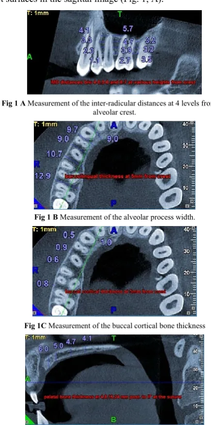
All images were oriented using a standardized protocol. On the axial image, the CBCT image was oriented until the green line supplied by the software was perpendicular to the buccal bone surface and bisects the inter-radicular area to be measured. On the sagittal image, the CBCT image was oriented until the occlusal plane is parallel to the blue line. The cursor was adjusted until the red line in the axial image was centered on each contact area, at approximately the midroot level. For each inter-radicular area in the maxilla and the mandible, from the distal aspect of the lateral incisor to the mesial aspect of the second molar of maxilla and mandible, the following measurements were done at four different heights from the alveolar crest, that was, at 2, 5, 8, and 11 mm.
Mesiodistal distance (MD): This distance was defined as the distance between parallel lines tangent to the adjacent proximal root surfaces in the sagittal image (Fig. 1, A).
Fig 1 A Measurement of the inter-radicular distances at 4 levels from the alveolar crest.
Fig 1 B Measurement of the alveolar process width.
Fig 1C Measurement of the buccal cortical bone thickness
Buccolingual alveolar process width (BL): This width was measured at the center of the inter-radicular width between the tangent lines to the proximal root surfaces, from the outermost point on the buccal side to the outermost point on the palatal/lingual side (Fig. 1, B).
Buccal cortical bone thickness (BC): This thickness was the distance between the external and internal aspects of the buccal cortex midway between the tangent lines to the proximal root surfaces (Fig.1, C).
Palatal bone thickness: Using the NNT Newtom®3G
software for each patient, we initially identified the incisal foramen from the axial section of the upper jaw. 90° paracoronal views of the palate region were reconstructed at 4, 8, 16 and 24 mm posterior from the incisal foramen, and measurements of the bone height were made in each reconstruction at 0, 3, and 6 mm increments laterally from the midline to describe the thickness of palate (Fig. 1, D).
80 measurements were done in each maxilla and 60 measurements were done in each mandible. A total of 1840 measurements were done in maxilla and a total of 1440 measurements were done in mandible. These measurements were performed by one investigator. The CBCT images of 5 patients were randomly selected and re-measured by the same examiner after a 4-week interval to test for intra-observer reliability.
Statistical analysis
The data were analyzed using the SPSS version 20.0 for windows. The significance level for all the tests was set at P < .05. Descriptive analysis was used to obtain the means and standard deviations (SD) of all the measurements. Independent-samples t-test was used for the comparison of various variables.
RESULTS
The means and standard deviations of the buccolingual alveolar process width, mesiodistal distance and buccal cortical bone thickness of the maxilla and mandible are shown in Table 1, 2 and 3, respectively.
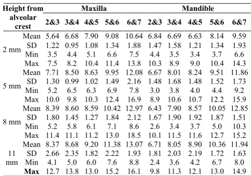
Table 1 Descriptive statistics of Buccolingual measurements in maxilla and mandible.
Height from alveolar
crest
Maxilla Mandible
2&3 3&4 4&5 5&6 6&7 2&3 3&4 4&5 5&6 6&7
2 mm
Mean 5.64 6.68 7.90 9.08 10.64 6.84 6.69 6.63 8.14 9.59 SD 1.22 0.95 1.08 1.34 1.88 1.47 1.58 1.21 1.34 1.93
Min 3.5 4.4 5.1 6.6 7.5 4.4 3.5 3.4 3.7 6.6
Max 7.5 8.2 10.4 11.4 13.8 10.3 8.9 9.0 10.4 14.3
5 mm
Mean 7.71 8.50 8.63 9.95 12.08 6.67 8.01 8.24 9.51 11.86 SD 1.30 0.99 1.02 1.49 2.16 1.48 1.68 1.48 1.52 1.73
Min 5.2 6.5 6.3 6.9 7.8 3.0 3.8 4.0 4.4 9.2
Max 10.0 9.8 10.3 12.4 16.9 8.9 10.6 10.7 12.2 15.9
8 mm
Mean 8.39 8.60 8.59 10.42 12.97 6.43 7.90 8.57 10.05 12.85 SD 1.80 1.45 1.27 1.84 2.12 1.67 1.90 1.92 1.87 1.51
Min 5.2 5.8 6.1 7.1 8.6 2.6 3.4 3.7 5.0 10.3
Max 11.4 11.1 11.2 13.0 18.5 10.1 11.5 11.6 12.7 15.2
11 mm
Mean 8.37 8.68 9.20 11.38 13.07 6.71 8.05 8.90 10.36 11.94 SD 2.66 2.35 1.82 2.22 1.93 1.81 2.03 2.19 1.72 1.63
Min 4.1 5.0 6.0 7.6 8.8 2.4 3.6 4.2 6.7 8.0
Max 12.7 13.8 13.0 15.2 16.1 9.8 11.3 12.1 13.0 14.9
In the maxilla
The greatest mesiodistal distance was between the second premolar and first molar at 11-mm height (3.72 ± 1.09 mm). The greatest buccolingual alveolar process width and buccal cortical bone thickness were between the first and second molar at 11-mm height (13.07 ± 1.93 and 1.35 ± 0.59 mm, respectively). As described by Poggio et al, 2006 and Monnerat et al, 2009, the safe site for placing miniscrew implant in the maxilla of our study is between the second premolar and first molar at 11-mm height (3.72 ± 1.09 mm), however, it should be careful about maxillary sinus position at this height. The average risk site is between the second premolar and first molar at 8-mm height (3.10 ± 0.90 mm), that is suitable for 1.2-1.3-mm diameter of miniscrew implant.
The data indicates that, for all variables, the measurements are gradually increased from cervical area to apical area. Small variations from this trend were observed between the first premolar and second premolar at 8 mm height and between lateral incisor and canine at 11 mm height (for BL). The variation was also observed between the first molar and second molar at 5 mm and 8 mm height (for MD). The buccal cortical thickness (BC) also showed variations from the general trend
Table 2 Descriptive statistics of mesiodistal distances (inter-radicular spaces) in maxilla and mandible.
Height from alveolar
crest
Maxilla Mandible
2&3 3&4 4&5 5&6 6&7 2&3 3&4 4&5 5&6 6&7
2 mm
Mean 1.75 2.06 2.15 2.36 2.25 1.71 2.08 2.70 2.85 ″3.69
SD 0.52 0.66 0.49 0.63 0.86 0.44 0.79 0.75 0.67 1.03
Min 0.9 0.9 1.1 1.2 0.6 0.8 0.6 1.4 2.0 1.5
Max 3.0 3.5 3.0 4.4 4.2 2.4 3.9 4.2 4.7 5.9
5 mm
Mean 2.30 2.32 2.50 2.47 2.01 2.59 2.66 ͯ3.39 ͯ3.23 ″4.49
SD 0.73 0.93 0.63 0.87 0.96 0.53 1.19 0.85 0.94 1.57
Min 1.1 0.9 1.4 1.0 0.2 1.4 1.1 2.1 2.0 0.5
Max 4.1 4.1 3.6 4.2 4.1 3.5 6.6 5.3 6.0 7.1
8 mm
Mean 2.93 2.80 2.93 ͯ3.10 1.97 ͯ3.50 ͯ3.51 ″4.17 ″3.72 ″5.83
SD 0.97 0.98 0.83 0.90 1.06 0.76 1.83 1.00 1.55 2.11
Min 0.9 0.9 1.7 1.2 0.2 2.0 1.2 1.7 2.1 0.5
Max 5.1 4.7 4.1 5.4 5.3 5.1 10.1 6.3 9.5 9.5
11 mm
Mean ͯ3.07 ͯ3.51 ͯ3.38 ″3.72 2.13 ″3.98 ″4.01 ″4.75 ″4.90 ″6.70
SD 0.97 1.31 1.02 1.09 1.40 1.14 1.39 1.12 1.77 1.89
Min 1.2 0.9 1.5 1.7 0.6 2.9 1.7 2.6 2.6 1.6
Max 4.4 5.3 4.8 5.7 5.0 6.2 6.8 6.8 10.7 11.0
ͯ
Average risk site ″ Safe site
Table 3 Descriptive statistics of buccal cortical bone thickness in maxilla and mandible.
Height from alveolar crest
Maxilla Mandible 2&3 3&4 4&5 5&6 6&7 2&3 3&4 4&5 5&6 6&7
2 mm
Mean 0.93 0.92 0.86 0.86 1.00 0.84 0.79 0.84 0.93 1.29
SD 0.39 0.34 0.30 0.32 0.34 0.37 0.31 0.35 0.32 0.57
Min 0.3 0.3 0.3 0.3 0.3 0.3 0.4 0.2 0.4 0.4
Max 1.9 1.5 1.5 1.7 2.0 1.8 1.6 1.6 1.6 2.2
5 mm
Mean 0.88 0.83 0.86 0.84 0.87 0.77 0.94 1.02 1.48 2.29
SD 0.32 0.23 0.29 0.34 0.24 0.27 0.36 0.28 0.55 0.88
Min 0.2 0.3 0.3 0.3 0.5 0.4 0.3 0.5 0.8 0.9
Max 1.6 1.2 1.5 1.5 1.5 1.3 1.6 1.6 2.8 4.0
8 mm
Mean 1.11 1.15 0.91 0.93 0.93 0.90 1.10 1.36 1.70 2.69
SD 0.33 0.35 0.25 0.35 0.43 0.28 0.38 0.48 0.42 0.62
Min 0.3 0.5 0.2 0.5 0.3 0.3 0.5 0.5 0.8 1.5
Max 2.0 2.1 1.4 1.6 1.9 1.4 2.0 2.1 2.6 3.9
11 mm
Mean 1.11 1.11 0.95 1.16 1.35 1.17 1.34 1.72 1.98 2.73
SD 0.34 0.31 0.22 0.60 0.59 0.40 0.47 0.52 0.60 0.58
Min 0.5 0.5 0.5 0.4 0.6 0.4 0.5 0.8 0.9 1.4
Screw Implant Placement Sites Using Cone Beam Computed Tomography
between lateral incisor and canine at 5 mm height; between canine and first premolar at 5 mm and 11 mm height; between second premolar and first molar at 5 mm height; and between first molar and second molar at 5 mm height, which were less than the height above them. The buccolingual alveolar process width increases from the anterior to posterior regions.
In the mandible
The greatest mesiodistal distance was between the first and second molar at 11-mm height (6.70 ± 1.89 mm). The greatest buccolingual alveolar process width was between the first and second molar at 8-mm height (12.85 ± 1.51 mm). The greatest buccal cortical bone thickness was between the first and second molar at 11-mm height (2.73 ± 0.58 mm).
As described by Poggio et al, 2006 and Monnerat et al, 2009, the safe and suitable sites were located between the lateral incisor and canine at 11 mm height( 3.98 ± 1.14 mm); between the canine and first premolar at 11 mm height (4.01 ± 1.39 mm); between the first and second premolar at 8 and 11-mm height (4.17 ± 1 mm and 4.75 ± 1.12 mm, respectively); between the second premolar and first molar at 8 and 11- mm height (3.72 ± 1.55 mm and 4.90 ± 1.77 mm, respectively); and between the first and second molar at 2, 5, 8 and 11-mm height (3.69 ± 1.03 mm, 4.49 ± 1.57 mm, 5.83 ± 2.11 mm and 6.70 ± 1.89 mm, respectively). However, the clinician should be careful about the mental foramen position between the first and second premolar. The sites of average risk were located between the lateral incisor and canine at 8 mm height (3.50 ± 0.76 mm); between the canine and first premolar at 8 mm height (3.51 ± 1.83 mm); between the first and second premolar at 5 mm height (3.39 ± 0.85 mm); and between the second premolar and first molar at 5 mm height (3.23 ± 0.94 mm).
The data shows that, for all variables, the measurements are generally increased from cervical area to apical area. A small variation from this trend was observed between the lateral incisor and canine at 5 mm height (for BC). The variation was also observed between lateral incisor and canine at 5 mm and 8 mm height, between canine and first premolar at 8 mm height, and between first and second molar at 11 mm height (for BL), which were less thick than the height above it.
Palatal bone has highest thickness (mean value of 8.88 ± 3.17 mm) at 4 mm posterior to the incisive foramen (IF), 6 mm to the lateral of mid-palatal suture and least thickness (mean value of 1.37 ± 1.17 mm) at 24 mm posterior to the incisive foramen, 6 mm to the lateral of mid-palatal suture.
The means and standard deviations of palatal bone thickness of the maxilla is shown in Table 4.
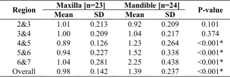
Table 5 shows comparison for buccal cortical bone thickness in maxilla and mandible, which is greater in mandible as compared to maxilla except for lateral incisor and canine region, where it is greater in maxilla.
Table 6 shows comparison for buccolingual measurements in maxilla and mandible, which is greater in maxilla than mandible and the difference is not statistically significant.
Table 7 shows comparison for mesiodistal distances in maxilla and mandible, which is greater in mandible than maxilla.
Table 4 Descriptive statistics of palatal bone thickness in maxilla
Distance from incisal foramen
6mm to the left of suture
3mm to the left of suture
At the Suture
3mm to the right of suture
6mm to the right of suture
4 mm
Mean 8.88 7.70 7.99 7.30 8.00
SD 3.17 2.42 3.73 2.48 2.48
Min 4.4 5.1 2.3 1.5 2.4
Max 17.8 16.6 16.8 14.4 12.6
8 mm
Mean 3.92 4.11 6.01 4.00 3.27
SD 2.01 1.77 2.24 1.77 1.57
Min 1.4 1.4 3.9 1.5 0.8
Max 8.1 8.4 11.4 7.8 6.8
16 mm
Mean 2.00 2.37 4.13 2.46 1.54
SD 1.61 1.28 1.35 1.95 0.97
Min 0.3 0.4 1.8 0.2 0.3
Max 6.8 5.4 7.5 8.4 3.2
24 mm
Mean 1.37 2.03 3.60 2.76 1.51
SD 1.17 1.39 1.53 2.09 0.88
Min 0.2 0.5 0.8 0.5 0.3
Max 6.0 5.3 6.6 8.6 3.5
Table 5 Comparison based on buccal cortical bone
thickness between maxilla and mandible.
Region Maxilla [n=23] Mandible [n=24] P-value Mean SD Mean SD
2&3 1.01 0.213 0.92 0.209 0.101
3&4 1.00 0.209 1.04 0.217 0.374
4&5 0.89 0.126 1.23 0.264 <0.001*
5&6 0.94 0.227 1.52 0.338 <0.001*
6&7 1.04 0.281 2.25 0.438 <0.001*
Overall 0.98 0.142 1.39 0.237 <0.001*
*Statistically Significant Difference (P-value<0.05)
Table 6 Comparison based on buccolingual measurements between maxilla and mandible.
Region Maxilla [n=23] Mandible [n=24] P-value Mean SD Mean SD
2&3 7.53 1.56 6.66 1.46 0.056
3&4 8.12 1.29 7.66 1.57 0.287
4&5 8.58 1.11 8.09 1.47 0.205
5&6 10.21 1.46 9.51 1.43 0.108
6&7 12.19 1.76 11.56 1.29 0.167
Overall 9.33 1.18 8.70 1.28 0.084
Table 7 Comparison based on mesiodistal (inter- radicular spaces) between maxilla and mandible.
Region Maxilla [n=23] Mandible [n=24] P-value Mean SD Mean SD
2&3 2.45 0.61 2.77 0.56 0.065
3&4 2.66 0.87 3.03 1.23 0.245
4&5 2.74 0.64 3.73 0.82 <0.001*
5&6 2.84 0.68 3.67 1.18 0.005*
6&7 2.10 0.92 5.18 1.49 <0.001*
Overall 2.56 0.38 3.68 0.49 <0.001*
Table 8 Summary of articles identifying the greatest mesiodistal distance in the inter-radicular areas of maxilla
and mandible.
Author Method Maxilla Mandible
Poggio et al., 2006 CBCT 4-5 , 5-6 4-5
Park and Cho, 2009 CBCT 5-6 6-7
Fayed et al., 2010 CBCT 5-6 5-6,4-5
Monnerat et al., 2009 CT - 6-7
Chaimanee et al., 2011 IOPAR 5-6 6 -7
Schnelle et al., 2004 OPG 5-6 5-6,6-7
Our study CBCT 5-6 6-7
DISCUSSION
This study determines the inter-radicular areas in the maxilla and mandible for safe and suitable orthodontic miniscrew implant placement. In the maxilla, we reported the greatest mesiodistal distance was between the maxillary second premolar and first molar. According to the Table 8, this result agreed with those obtained in previous studies of both 2D and 3D method (Fayed et al, 2010; Chaimanee et al, 2011; Park and Cho, 2009; Schnelle et al, 2004). However, they are different from the study of Poggio et al, 2006, probably due to the difference in the method of measurement in these studies.
In the mandible, we reported the greatest mesiodistal distance was located between the first and second molar. According to the Table 8, this result agreed with those obtained in previous studies of both 2D and 3D method (Chaimanee et al, 2011; Park and Cho, 2009; Monnerat et al, 2009). However, they are different from the studies in CBCT method of Poggio et al, 2006 and Fayed et al, 2010 probably due to difference in the method of measurement in these studies. Moreover, the vertical and horizontal magnifications are inherent in panoramic radiography, as the method of Schnelle et al, 2004, the result from this study is different.
According to our study, the sites of safe and average risk of miniscrew implant placement are more than 6–8 mm of buccolingual alveolar process width and more than 1.0 mm of cortical bone thickness. This is in accordance with the studies of Poggio et al, 2006 and Motoyoshi, 2011. Stability is influenced significantly by cortical bone thickness at the miniscrew implant placement site. In addition, the bone quality (bone mineral density) and the presence of attached gingiva are factors that influence stability (Papadopoulos and Tarawneh, 2007; Park and Cho, 2009). These factors should be studied further.
The cortical bone thickness in the mandibular buccal region was significantly greater than maxillary buccal region in our study. The results of this study in terms of cortical bone thickness for mini-implant placement are in agreement with the results obtained by Deguchi et al, 2006and Motoyoshi et al, 2008. Thicker cortical bone in the buccal region of the mandible might be explained biomechanically. Whereas the mandible is under torsional and bending strains, the maxilla is generally subjected to more compressive forces. Animal experiments have demonstrated that regions that experience higher strain during function develop thicker cortical bones. Motoyoshi et al, 2007 showed that the odds ratio of failure were 6.9 times greater when cortical bone was less than 1 mm thick than when it was thicker than 1 mm. Increased thickness of cortical bone in mandible could explain the higher failure rates reported for the mandible.Bone with thicker cortex, such as the mandible and infrazygomatic crest, might be expected to undergo greater damage (crushing and heat) during placement. Therefore, pilot holes might be required to mitigate this damage for certain patients.
In the present study, we analysed the Digital Volumetric Tomographies of 23 patients with ages ranging between 14 and 42 years and measured the thickness of the palatine bone in 20 different sites in an attempt to identify the region of the palate most suitable for the insertion of miniscrews. This study analysed the bone thickness at 4 different paracoronal sections.
For each section, the height of the palatal bone at 0, 3 and 6 mm increments laterally from the midline was measured. The results highlight that the major thicknesses of the palate are found at 6 mm to the left and right of the suture in the anterior part of the palate, 4 mm from the incisal foramen.
Nevertheless, it is interesting to observe, using the different sections, how the morphology of the palate varies. In the anterior part of the palate, the thickest bone is found laterally at 6 mm from the midline while the thinnest bone is at 3 mm.
In the 8 mm section, the variations are smaller but the morphology changes noticeably as the thickest bone was at the suture and thinner bone continued to be found bilaterally at 3 mm.
In the 16 mm section, the situation changes further. The thickest bone is again noted at the suture. However, the bone thicknesses at 3 and 6 mm, which are almost similar, are much lower with respect to the suture.
Finally, in the 24 mm section, the palatine morphology changes further as the thicknesses tend to progressively decrease from the suture to the sides.
The study is in consonance to the literature where it has been reported that the palate is a site of choice for insertion of miniscrews (Schlegel et al, 2002). In particular, the largest bone thickness is found in the anterior region of the palate, 4-8 mm from the foramen both at the suture and at the paramedian areas. The more posterior regions of the palate are also suitable for housing the miniscrews despite the fact that the bone is thinner because the quality of the bone (double cortical) and the thickness of the adhering mucosa which covers it provide stability for the minicrews.
It is necessary to point out that there is concensus agreement that the suture, despite being among the thickest sites in the different palatal sections, is not the site of choice for the insertion of miniscrews due to its incomplete calcification that can also be seen in adult subjects. Consequently, the paramedian region is the most suitable area for the positioning of miniscrews and the best areas are those at 6 mm in the 4 and 8 mm paracoronal view and those at 3 mm in the 16 and 24 mm paracoronal view because the bone is thickest in these sites.
CONCLUSION
Following conclusions were made from our study:
1. Buccal cortical bone thickness increases from crest to apex and from anterior to posterior regions, and more remarkable increase is seen in mandible. Mandibular buccal cortical bone is much thicker than maxilla and the difference is statistically significant. Buccal cortical thickness is more in posterior sextants than in anterior sextants in both maxilla and mandible. However, there is a little bit of variation in this general trend for maxillary anterior sextants in which cortical bone thickness is slightly higher than the adjacent posterior sextant.
Screw Implant Placement Sites Using Cone Beam Computed Tomography
3. At the buccal aspect of posterior region the safest zone in the inter-radicular space of the posterior maxilla was the space between the second premolar and first molar. In the posterior mandible, the safer zones were located between the first and second premolars and between the first and second molars. The mesiodistal distances increase from cervical to apical area. They are greater in mandible than maxilla and the difference is statistically significant.
4. Palatal bone is thickest anteriorly and the thickness decreases posteriorly. For anterior regions of palate, bone thickness increases lateral to mid-palatal suture i.e. it is more in paramedian regions than at the mid-palatal suture. For posterior regions of palate, bone thickness is more at the mid-palatal suture and decreases lateral to the suture.
These findings are statistical evaluations of data coming from a group of non-treated patients. They represent a guide for the clinicians but do not eliminate the need for a radiographic evaluation in each individual case before miniscrew insertion and CBCT evaluation is a useful method for assessing the safe zones for mini-implant placement.
References
Baumgaertel S, Hans MG. (2009): Buccal cortical bone thickness for mini-implant placement. Am J Orthod Dentofacial Orthop, 136(2):230-5.
Bills DA, Handelman CS, BeGole EA. (2005): Bimaxillary dentoalveolar protrusion: traits and orthodontic correction. Angle Orthod, 75(3):333-9.
Chaimanee P, Suzuki B, Suzuki EY. (2011): "Safe zones" for miniscrew implant placement in Different dentoskeletal patterns. Angle Orthod, 81(3):397-403. Chung KR, Nelson G, Kim SH, Kook YA. (2007): Severe
bidentoalveolar protrusion treated with orthodontic microimplant-dependent en-masse retraction. Am J Orthod Dentofacial Orthop, 132(1):105-15. Deguchi T, Nasu M, Murakami K, Yabuuchi T, Kamioka H, Takano- Yamamoto T.(2006):
Quantitative evaluation of cortical bone thickness with computed tomographic scanning for orthodontic implants. Am J Orthod Dentofacial Orthop, 129:721.e7-12.
Farnsworth D, Rossouw PE, Ceen RF, Buschang PH. (2011): Cortical bone thickness at common miniscrew implant placement sites. Am J Orthod Dentofacial Orthop, 139(4):495-503.
Fayed MM, Pazera P, Katsaros C. (2010): Optimal sites for orthodontic mini-implant placement assessed by cone beam computed tomography. Angle Orthod, 80(5):939-51.
Miyawaki S, Koyama I, Inoue M, et al. (2003): Factors associated with the stability of titanium screws placed in the posterior region for orthodontic anchorage. Am J Orthod Dentofacial Orthop,124(4):373-8.
Monnerat C, Restle L, Mucha JN. (2009): Tomographic mapping of mandibular interradicular spacesfor placement of orthodontic mini-implants. Am J Orthod Dentofacial Orthop, 135(4):428 e1-9; discussion 28-9. Motoyoshi M. (2011): Clinical indices for orthodontic
mini-implants. J Oral Sci, 53(4):407-12.
Ono A, Motoyoshi M, Shimuzu N. (2008): Cortical bone thickness in the buccal posterior region for orthodontic mini-implants. Int J Oral Maxillofac Surg, 37:334-40. Papadopoulos MA, Tarawneh F. (2007): The use of
miniscrew implants for temporary skeletal anchorage in orthodontics: a comprehensive review. Oral Surg Oral Med Oral Pathol Oral Radiol Endod, 103(5):e6-15. Park HS, Bae SM, Kyung HM, Sung JH. (2001):
Micro-implant anchorage for treatment of skeletal Class I bialveolar protrusion. J Clin Orthod, 35(7):417-22. Park J, Cho HJ. (2009): Three-dimensional evaluation of
interradicular spaces and cortical bone thickness for the placement and initial stability of microimplants in adults. Am J Orthod Dentofacial Orthop, 136(3):314 e1-12; discussion 14-5.
Poggio PM, Incorvati C, Velo S, Carano A. (2006): "Safe zones": a guide for miniscrew positioning in the maxillary and mandibular arch. Angle Orthod, 76(2):191-7.
Sawada K, Nakahara K, Matsunaga S, Abe S, Ide Y. (2011): Evaluation of cortical bone thickness and root proximity at maxillary inter-radicular sites for mini-implant placement. Clin Oral Implants Res, 1-7.
Schlegel KA, Kinner F, Schlegel KD. (2002): The anatomic basis for palatal implants in orthodontics. Int J Adult
Orthodon Orthognath Surg, 17(2):133-9.
Schnelle MA, Beck FM, Jaynes RM, Huja SS. (2004): A radiographic evaluation of the availability of bone for placement of miniscrews. Angle Orthod, 74(6):832-7.