Consideration of Easygard Post Design on The Base of
Advanced Concurrent Engineering Tool
1
Alexander SHARMAZANASHVILI
2
Huseyin ONAL
Abstract
The essence of CE is the integration of product design and process planning into one common activity. Concurrent design helps improve the quality of early design decisions and has a tremendous impact on life-cycle cost of the product. It is important to decide at an early stage in design which type of assembly method is likely to be adopted, based on the method yielding the lowest costs. This section allows the designer to decide, from the values of basic product and company parameters (production volume, number of parts, etc.) which assembly method is likely to be the most economic.
The purchase of special-purpose automation equipment (high-speed automatic assembly) would almost certainly provide excellent return on investment. Somewhere between these extremes is a range of annual production volumes for which robot assembly might be the best economic choice if the assembly were appropriately designed. However, changing system is not only the way to reduce the production time and cost. It is also possible to reduce time and cost significantly by using software package and designing or redesigning assembly of product appropriately.
Paper below represents design optimization possibilities by DFA approach for Easygard post engineering design produced by one of the UK medium size manufacturing company.
Keywords: DFA, Easygard post, Concurrent Engineering.
Introduction
The traditional design process is a serial process in which the design is passed through the various modules; should a design change be necessary, the design is returned to the top and the process is repeated. This iterative process had been carried out routinely in the United States for many years. The various domain experts are almost always located in physically separate departments, and communication among them is sometimes difficult. Worse given for this traditional serial approach to design includes the following:
?Product development is traditionally its own organization and is physically and organizationally isolated. Process development and production operations are located together different organization labeled manufacturing.
?Most emphasis is on manufacturing operations, that is, shipping product out the door.
As a result, United States is losing ground in the manufacturing of produces to other countries such as Japan and Germany (Kusiak A.1992). These countries have realized the problems in current design practices and have modified the
1
Assist Profesor, Georgian Technical University, [email protected]
process to solve some of these problems. Concurrent engineering has as its purpose to detail the design the design while simultaneously developing production capability, field-support capability, and quality. It consists of a methodology using multidiscipline teams to carry out this concurrency: CE tools in the form of algorithms, techniques, and software, and the expertise and judgment of people who make up the complete design and production sequence. The essence of CE is the integration of product design and process planning into one common activity. Designer, in this case, is represented by the hub of the wheel (figure 1), coordinates the comments and redesign suggestions from each of the domain experts around the circumference.
Figure 1
One of the sophisticated tools of CE is Design for Assembly (DFA). DFA is the integration of product design and assembly process design into one common activity. The goal is to design a product that is easily and economically assemble. Consideration of assemble guidelines is an essential part of DFA.
DFA guidelines are statements of good design practice derived empirically from many years of design and assembling experience. They differ from design axioms in that the axioms are self-evident truths which are so obvious to need no proof. Axioms are generated by examination of a complete process and generalizing principles. Corollaries are applications of the axioms. Alternatively, a guideline is a standard by which to make a judgment. Guidelines are generated by polling designers about specific rules used during design.
product function. Given that these to aspects of the design constraints can be satisfied, the DFA guidelines address the processing practices.
Considerable effort beyond in development of DFA approach was done by Geoffrey Boothroyd and Peter Dewhurst and by their owned company BoothroydDewhurst, Inc (BDI). According to BDI (Boothroyd G. and Dewhurst P.. 1989), the best way to achieve this cost reduction is first to reduce the number of individual parts that must be assembled and then to ensure that the remaining parts are easy to manufacture and assemble. The analysis technique is systematic in its approach and is a formalized step-by-step process. Manufacture and assembly costs are largely determined at the design stage. Moreover, combined parts are usually much less expensive that the combined cost of the separate parts. Use of the approach involves three important steps for each part in the assembly:
1. A decision as to whether the part can be considered a candidate for elimination or for combination with other parts in the assembly:
2. An estimation of the time taken to acquire, grasp, manipulate, and insert the part (assemble). If necessary, the time to acquire and replace the tool will he included.
3. Documentation of additional assembly, manufacturing and tooling costs for the item.
Using this approach it is possible to examine the features of design in a systematic way to obtain a DFA index. This index can be used to compare different designs. User-defined entries to the DFA index analysis process can also be used to track important parameters such as suppliers, lead times, and quality levels, etc.
Description of Easygard Engineering Design
Easygard Post is a part which is used to stop the machine in fixed position. Outer post of Easygard post is under the ground and post part of that is a moving part traveling up and down. When inner post is out of its nest, it means it is above the ground; it contacts with the particular part of machine and makes it stand in fixed place. There is a motor in outer post, this motor is making the inner post travel up and down when motor is rotating in one direction it pushes the screw up and then it is turning in opposite direction, it pulls the screw down through itself
?Jack Screw - length is 800 mm, and diameter is 25 mm. But one end of 10 mm. of the jack screw is smaller than whole part. Its diameter is 15 mm. It has Ix45deg chamfer on it so that it is easy to insert the other parts on the screw the part with dia-15mm is adjusted for the parts that will be inserted on the screw. There are two holes on it for Bissell pins with the same diameter, 6.2mm. Screw has 0.875 diameters with 5 TP1 acmes 4 start thread. This thread is consistent with the ones of motors, so when motor is working, screw goes through the motor up and down. This movement is the main action of the Easygard Post.
?Bissell Pin I - This part has 50mm length and 6mm diameter. Its function is to stop the screw go through the motor further more. It has champers on both ends to make the assembly easy. Bissell pin I is assembled on screw by inserting it through the hole which stands close the motor.
?Bissell Pin II - Length and diameter of the Bissell Pin are l00 mm and 6 mm. respectively, Its function is to contact with the key at particular point to stop the screw. It has champers on both ends of the Bissell pin to make the insertion easy. It is inserted into jack screw through the hole which stands on upper side of the screw.
?Top Screw Bearing - Outer diameter and inner diameter of the top screw bearing are 32mm, and 15 mm. respectively And its thickness is 9mm. This is the deep Groove Ball Bearing NTN 6002 Type N cat No 2200/E. After placing outer support plate, this part is put on jack screw.
?Top Bearing Inner Support Plate - Size of the part is similar to the outer support plate, it's a rectangle with the measurements 75x50
2
diameter 6.2mm. After assembling washer, this part is assembled on ball bearing and washer fixed on the screw, mating the inner surface of the plate with the outer surface of ball bearing and washer. This is made of 4 mm thick cold balled mild steel.
?Top Bearing Outer Support Plate - This is a rectangle shaped with
2
75x50 mm there is a circle at the centre with diameter 32 mm and also 4 M6 thick cold rolled mild steel. After assembly Bissell pins, this plate is placed on the jack screw.
?Top Bearing Distance Washer its outer and inner diameters are 36.8 mm and 26 mm. respectively and It is made of 1. 5875 mm thick Rubber. After ball bearing is fixed on jack screw, washer is placed around ball bearing. After all these assembly process outer cover case plate and outer support plate are fastened by screws, M6 Tamperproof Pan head screws. So our jack screw sub assembly is assembled in inner post from inside.
DFA Implementation
In order to get and use the evaluation reports from DFMA. it is necessary to enter data of the parts considered above. Such as measurements of the parts, features of them, like slippery, sharp, fragile, flexible or etc., should be entered.
As a result, DFMA software gives several reports for redesigning or just as information:
?DFA Structure Chart Report - sequence of assembly, time and cost required for assembly are presented
?DFA Production Review table Report - for each part, required time and cost presented in details. For example - tool fetching time handling, labor cost, item cost, etc.
?DFA Suggestions For Redesign Report - suggestions may reduce time and cost required for assembly, eliminating some assembly difficulties or reducing number of items.
?DFA Responses Report - definitions, minimum part criteria, shape, size. Difficulties faced, and fetching distance are presented.
According to this reports following results have to be considered. Total subassembly time and cost are 58.18sc. and $0.97 respectively. As we see in Responses Report reasons that make the assembly time-consuming and costly are seen. For each item, definition repeat minimum part criteria, shape, symmetry, size. handling-insertion difficulties and fetching distance are shown. For example: For Jack Screw we do not have handling and insertion difficulties but for Bissell pin 1 we have slippery, view handling and insertion difficulties. And so on. As long as we eliminate these difficulties, the total time and cost will be reduced. In this case we must look at Redesign report. In this report DFA suggests us what to do to reduce time and cost of assembly. Those important suggestions are as following:
others or eliminating the following parts or subs. Bissell Pin I and Bissell Pin II. Combining them looks to be so difficult because their functions are different and their places are away from each other. But we can eliminate one in a different way, we will discuss this later. If we achieve to eliminate one of them we will save 9.04 sec. for two we will save 18.08 sec.
?Add assembly features such as chamfers, lips, leads, etc., to make the following items self-aligning:
Top Bearing,
Outer Support Plate,
Top bearing Inner Support Plate
If we eliminate such difficulties we will save 1.50 sec for each item, so total 6 sec.
Redesign the assembly where possible to allow adequate access and unrestricted vision for placement or insertion of the following items:
Bissell Pin I Bissell Pin II Top Bearing
Top Bearing Inner Support Plate.
If we eliminate the problem related with unrestricted vision, we will save 2.20 sec. for each, and totally 8.80 sec.
Consider redesign of the individual assembly items listed below to eliminate or reduce handling difficulties which include one or more of the following nest or tangle, stick), fragile, slippery, and sharp.
Bissell Pin I Bissell Pin II Top Bearing
Top Bearing distance washer
If we eliminate the difficulties for Bissell Pin I and II we will save 0.71 sec for each and for Top Bearing we save 0.75 sec and Top Bearing distance washer we will save 0.76 sec. Totally, 2.93 sec.
Consider Redesign of the individual assembly items listed below to eliminate resistance to insertion or severe insertion difficulties:
Bissell Pin and Bissell Pin II
But no need to deal with these difficulties because there is no time saving.
Optimization Paradigm
In this Sub Assembly the reason for slippery and view difficulties is because of small shape of the relevant items, in order to eliminate these difficulties, the sizes of the items must be enlarged.
For alignment difficulties, this is because relevant items do not have champers. When we put chamfers, difficulties will be eliminated.
For insertion difficulties, I do not think that we have something to do
?
?
This is because Press tilting is a method used in assembling relevant items. Here is also one suggestion of DFA that we can do about it. This suggestion is about eliminating item or items. But in Redesign report it is not presented how to apply, how to do it. So it is necessary to find out ways in this direction. We will consider the items separately and try to change the size of them or eliminate one or more of them. While making changes on an item we must consider the other items related to it Changes on one item must not stop other's functions.
Jack Screw
At first look, enlargement of screw is not needed because in responses report, screw does not have any difficulties but since other parts are assembled on Jack Screw, any change on any item will affect the screw, so we have to enlarge the screw to fit other parts. Therefore let's determine the maximum size that we can extend it. We can not enlarge the screw as much as we can because we have some restrictions, first of all if we enlarge whole screw we will have to change the size of motor maybe size of outer cover also. This does not seem to be reasonable since changing on motor and outer post is so difficult and can bring many other changes needed on the parts related to them. That will be more costly and time-consuming. If we enlarge only the part of the screw left above the motor when screw is in nest then we do not have to make changes on the size of the motor and outer cover.
Now only two items left restrict the enlargement of the screw, the key and inner cover. Since the key is between Jack Screw and inner post, we do not have to consider the inner post because we can only enlarge the diameter of the screw up to the key. And now questions are what the distance between Jack screw and key is and weather we make the key move further away from jack screw or not.
The key is placed on outer cover base plate. This plate is a square shaped with the dimensions
2
160x160 mm . And key is placed on base plate. That circle with 30 mm diameter is a hole on base plate for key. We have 15 mm space to shift the hall, lets leave 5 mm between the edge of the base plate and the key this 5
2
mm is because although dimensions of base plate is 160x160 mm .
2
5 mm or so. Now we can move the key 10 mm away from its former place (figure 4).This 45 mm means that we can enlarge the diameter of jack
screw up to 90 mm. But what do we need to enlarge jack screw for?
What happens if we increase dimensions as much as we can?
?We will have to use more material so it will be costly
?Weight of material will increase.
?The fraction will increase between jack screw and Bissell pin I and II .
?As a result, we must increase the diameter of jack screw to extend that is needed. To find out the dimensions of the screw first we will consider other items related the screw then decide the dimension of the screw.
Bissell Pin I
Bissell Pin I has handling and insertion difficulties. In order to eliminate these difficulties I decided to expand its size. Before we consider how much we will enlarge. we should determine the whether there is space to enlarge or not. There are only two items that constraint the enlargement of Bissell pin I, there are inner post and jack screw. We can extend the length of the Bissell pin I up to inner surface of the inner post that's the
2
square shaped 157x157 mm so we can extend the diameter of Bissell pin 1 up to 157 mm but since we do not want to deal with fraction we should leave nearly 2 mm gasp between inner post and Bissell pin I, so length of Bissell pin I is 155 mm.
As for its relationship between the screws, while assembling we insert the Bissell pin 1 into the hole in which exists in jack screw. So deciding to enlarge the diameter of Bissell pin I we must consider the diameter of jack screw. Because as long as we enlarge diameter of Bissell pin 1, the hole must be expanded. If the diameter of hole reaches the diameter of jack screw, screw becomes weak, leading to breaking off at that point.
In order to remove slippery and view difficulties for Bissell pin I, we nearly make the size of Bissell pin I double. And this enlargement seems to be quite enough. So diameter of Bissell pinI will be 10.2 mm and of course the diameter of the hole will be a bit less than 10.2 mm. It must be a bit less as mentioned above because Bissell pin I is stuck into hall by press fitting but here we ignore that small difference and we say diameter of the hole is 10.2 mm. So for Bissell pin I we do not have to increase diameter of screw. 25 mm is enough to drill a hole with diameter 10.2 mm on it. But we must be careful with the function of Bissell pin I. Its function is to stop the screw at a particular point while traveling into motor. Since we increase 4 mm the diameter of the Bissell pin I, the point is moved down 2 mm from the former point. So, we must drill the hole 2 mm above so that the point remains at the same place (Figure4).
is 155 mm. The changes did not affect the Jack Screw.
Bissell Pin II
Shape of Bissell Pin II is like Bissell pin I, its length is 100 mm, and diameter is 6.2 mm. This item is also inserted into the hole in jack screw. Its function is to contact with the key. So restrictions in changing on its shape are the key, inner post and jack screw. As we mentioned above to eliminate the handling and insertion difficulties we should enlarge it as we did on Bissell pin I. So length of it is 155 mm and diameter is 10.2 mm (Figure4).
Again as mentioned above inner post does not prevent us making Bissell pin II enlarge but it contacts with the key at a particular point since we enlarge the diameter of it 4 mm. It means that we must drill the hole 2 mm below than former place. Considered changes on Bissell pin II did not affect length and diameter of jack screw.
Top Screw Bearing
Measurements of the part as follows: Outer diameter is 32 mm inner diameter 15 mm. And thickness is 9 mm. We see in response report that while assembling we face handling and insertion difficulties. We face handling difficulties because the longest diameter of the part is only 32 mm. And it is not easy to grasp down in correct direction. As far as it is seen in responses report, symmetry is 360x0 it means that both surfaces are not the same; we must hold the mating surface down, we face insertion difficulties because it does not have self-locating features. And we face also resistance because this item is assembled on jack screw by press fitting.
between screw bearing and outer support plate. In order to eliminate this difficulty we will put chamfer on outer support plate.
The question is how long we should enlarge it. Distances between centers of the outer cover base plate and key is 45 mm we can enlarge the diameter up to 90 mm but I think no need to use 90 mm up, just enough to enlarge it until handling becomes easy. 20 mm looks to be enough to work the problem out. Now, outer diameter is 52mm and inner diameter of screw bearing is 35 mm, shown on Figure 5.
We see that former inner diameter of screw bearing increased 35 mm. So top part of the jack screw, on which screw bearing is stuck, must be increased from 15 to 35 mm. Now we have jack screw with the diameter 35, to hold the bearing and other items of which places are on top part of the jack screw, we must increase the that part of the jack screw between outer support plate and motor. In that way the items assembled on top of the jack screw cannot slip down. So we increase the diameter of jack screw 10 mm. now dimension of jack screw is changed as shown on Figure 5, the difference between diameter of top part and diameter of largest part of jack screw is remained 10mm. as before.
Top Bearing Inner Support Plate
But it has view and alignment difficulties. If enlarge inner diameter and if we put chamfer around hole in the center of the plate, these difficulties will be eliminated.
Since measurements of screw bearing were changed, we will have to make some changes on inner plate. Normally diameter of inner-plate must be consistent with the outer diameter of screw bearing so
we must increase the inner-diameter of inner-plate up to 57.1mm as shown on Figure 6. but how innerplate is affected as a wholepart. When inner diameter is increased, can we drill a hole with that diameter on that plate? It looks clear that is impossible because its shape is a rectangle with
2
the size 75x50 mm . One edge is less than the diameter of the hole needed to drill on plate. We must increase the small edge of the plate that the hole with diameter 57.1 mm. can be drilled.
So we must increase it up to 65 mm in order to leave enough space between the hole and edge of the plate, this gasp is just because the strength of the plate must not be removed. What about the other 4 holes on it, do we have to change their locations? How they stay near each other? Do their places coincide? As a result of our calculations we see that there is enough space between holes, but we can move the small holes to he corners, it is obvious that not to make the material weak we should place the holes away and symmetric form each other by leaving enough a places from edge of the plate (Figure 7) In that way we will have to put holes on outer support plate, on the cover plate as the ones on inner support plate. We put the holes in corners considering the measurements as they are in original plate.
Top Bearing Outer Support Plate
This plate is placed on top part of the plate after the screw bearing is inserted in it. Or first screw bearing is inserted in outer plate then they are together placed on the top of the screw. It means that inner hole must be enlarged as much as the outer diameter of screw bearing. Inner diameter of the plate is 32 mm. and outer diameter of screw bearing was 32 mm. this diameter of screw bearing has been increased to 52 mm it means that inner diameter of the plate will be increased up to 52 mm.
But we face some restrictions as in inner plate, as we did there we
2 2
and also the 4 holes will be moved to the corners with the same measurements as inner plate. They must be at the same coordinates because inner, outer support plates and outer cover base plate are fastened.
As it is described in Responses report there is relative movement in assembling, because we assemble outer plate before screw bearing. Since inner diameter of outer plate is greater than top part of the jack screw, outer plate does not stand in fixed position. So assembling screw bearing between outer surface of jack screw and inner surface of the plate we will face alignment and relative movement difficulties. In order to eliminate the difficulties we first assemble screw bearing on the plate, and place them on jack screw. While assembling them again we face alignment difficulty because none of them has chamfer therefore we put chamfer around the hole on the plate.
Top Bearing Distance Washer
This item is the last item to assemble on the jack screw. This is made of rubber. As we see in responses report we face handling difficulty called slippery because its size is not large enough to gasp well while assembling it manually. Its measurements are as following: outer diameter is 36.8 mm, inner diameter is 26 mm., thickness is 1.5875 mm. Distance washer is assembled around the screw bearing, it has alignment difficulty its inner diameter is less than outer diameter of screw bearing so while assembling we make it enlarge by hand. Since we enlarged already screw bearing, we have to increase the size of washer too. In that way we eliminate the slippery. As for alignment difficulty this will remain because their sizes of mating places are different, we enlarge the washer by hand. Since we enlarge the size of washer, alignment becomes easier to some extent, because if there is no handling problem then alignment will be easy also.
We enlarge the size of washer considering screw bearing since we increased the diameter of screw bearing 20 mm then we increases the outer and inner diameter of washer 20 mm as well. As we mentioned above we now the figure out the final size of the jack screw, we considered all items related with jack screw and we made some changes on jack screw, shown on Figure 8.
Reducing number of item
Only the diameter of holes and diameter of part of the jack screw above the point at which Bissell pin I and motor touches are enlarged. As mentioned above function of Bissell Pin 1 is to stop the jack screw go into motor at a particular point in which they touch. Since we enlarged part of the screw that remains above the motor always, it cannot go into motor, it stops itself going into motor it means we do not need Bissell Pin I anymore. In that way we save 9.4 sec, and $0.15.
Evaluation of DFA Reports After Redesign
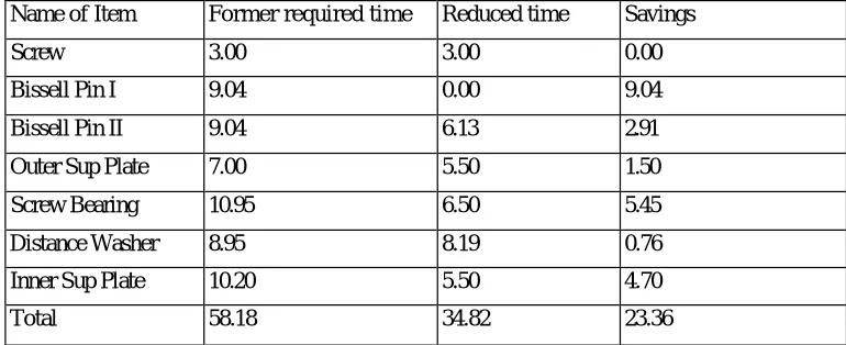
After entering new data into DFA software program. We get reports, called structured chart reports, production review table report, suggestion for redesign report, and responses report Total required time and cost are 34.82 sec. and $0.58 respectively. And their distribution for each item is presented in this report.
In table 1 and table 2 former records and new ones are presented.
Table 1
Table 2 Cost shown in $
Name of Item Former required time Reduced time Savings
Screw 3.00 3.00 0.00
Bissell Pin I 9.04 0.00 9.04
Bissell Pin II 9.04 6.13 2.91
Outer Sup Plate 7.00 5.50 1.50
Screw Bearing 10.95 6.50 5.45
Distance Washer 8.95 8.19 0.76
Inner Sup Plate 10.20 5.50 4.70
Total 58.18 34.82 23.36
Name of Item Former required cost Reduced cost Savings
Screw 0.15 0.05 0.10
Bissell Pin I 0.15 0.00 0.15
Bissell Pin II 0.15 0.10 0.05
Outer Sup Plate 0.12 0.09 0.03
Screw Bearing 0.18 0.11 0.07
Distance Washer 0.15 0.14 0.01
Inner Sup Plate 0.17 0.09 0.08
In DFA Redesign Report, there are two DFA suggestions:
?Reduce the number of items in the assembly by combining with other or eliminating the following parts of sub.
Bissell Pin II, Distance Washer, and Screw Bearing.
To follow this suggestion is impossible because we cannot combine the distance washer with other two because distance washer is made of different material, rubber, as for other two items their functions are different.
?Add assembly features such as chamfer, lips, leads, etc., to make the following items self-aligning: Distance washer
Thickness of Distance washer is no enough to add chamfer. In order that we add chamfer to the Distance washer we should enlarge the thickness of it. But it is not worth to try to add chamfer because its inner diameter is less than diameter of screw bearing on which washer is assembled. So we enlarge it by hand and place on the screw bearing. Diameter of 10 mm part of jack screw increased from 15 mm to 35 mm. And diameter of 135 mm part of jack screw increased from 25 mm to 45 mm. So we used extra material:
Table 3
Because of eliminating Bissell Pin I we reduced the material by amount of
Net extra used material =
3
If we say that 1 mm is 0.000 1 cent, the extra cost will be $0.15
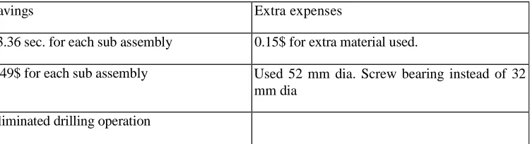
If we summaries savings and extra expenses we are incurred, we get the following results:
Conclusions
?As we see in first table reduced the assembly time is 23.6 sec. especially in mass production it is a great advantage. For example: if we produce one in 58.18 sec. then we produce 61.87 pieces in one hour. But if we produce one in 34.82 sec. then we produce 103.38 pieces in an hour. This example shows the advantage apparently.
?As for cost we reduced it from $0.97 to $0.58 but in this reduction, there are some other expenditure that we ignore. For example: We enlarge the diameter of some items it means we used extra material and it will cost us, Here we will just consider the extra material for jack screw, because
(
2) (
2) (
2) (
2)
388 . 157498 135 5 . 12 10 5 . 7 135 5 . 22 10 5 .
17 n n n mm
H× × + × × × × + × × =
(
2)
35352 . 1509 50 1 .
3 m m
n× × =
( ) 3
3 4 5 2 . 1 5 5 9 8 9 5 3 5 2
. 1 5 0 9 8 8 .
1 5 7 4 9 8 = m m
Savings Extra expenses
23.36 sec. for each sub assembly 0.15$ for extra material used.
0.49$ for each sub assembly Used 52 mm dia. Screw bearing instead of 32 mm dia
amount of the material used for others is minor.
?We eliminated Bissell Pin I it means we reduced also cost of material used to produce Bissell Pin I,
?While eliminating Bissell pin I we also reduced the drilling operation which is needed for Bissell Pin I.
?We spent $0.15 for extra used material for each sub assembly.
References
Kusiak A.(1992), Concurrent Engineering. Automation, Tools and Techniques, Wiley Publishers.