(www.rdmodernresearch.com) Volume 4, Issue 1, 2019
26
PROGRAMMABLE ROBOTIC ARM REPLICATING
MASTER ROBOT
T. Venkataramana*, A. Shashikumar**, G. Akhil*** &
G. Harshavardhan****
Department of Mechanical Engineering, Guru Nanak Institute of Technology, Rangareddy, Telangana
Cite This Article: T. Venkataramana, A. Shashikumar, G. Akhil & G. Harshavardhan, “Programmable Robotic
Arm Replicating Master Robot”, International Journal of Scientific Research and Modern Education, Volume 4, Issue 1, Page Number 26-31, 2019.
Copy Right: © IJSRME, 2019 (All Rights Reserved). This is an Open Access Article distributed under the Creative Commons Attribution License, which permits unrestricted use, distribution, and reproduction in any medium, provided the original work is properly cited.
Abstract:
A Robotic arm is a robotic manipulator usually programmable, with similar functions to a human arm. Servomotor is used for joint rotation .it has about same number of degree of freedom as in human arm. Humans pick up with outthinking about the steps invalid. In an order for a robot or a robotic arm to pick or more something. Some has to tell it to perform several actions in a particular order from moving the arm, to rotating the wrist to opening or closing the hand are finger. So we do control each joint through computer interface. The arm has 8 servo mechanisms for precise control of angular poison. The RC servomotors usually have a rotation limit from 90 to 180 degrees. Bur servo doesn’t rotate continually. They are used in robotic arm and legs, sensor scanner and in RC toys. It can be used for performing take like welding, gripping, spinning in space. In medical science (neurone). The arm is for manufacturing units decreasing human labour. Reducing human stress nothing but workload.
Key Words: Gripper, Servo Moter & Arduino Introduction:
Robotics is a branch of engineering and science that includes electronics engineering, mechanical engineering and computer science and so on. This branch deals with the design, construction, and use to control robots, sensory feedback and information processing.
Robotic is defined as the study, design and use of robotic systems for manufacturing. The rise in manufacturing industrial activities, a robotic arm is invented to help various industries to perform a task or work instead of using manpower. Robots are generally used to perform unsafe hazardous. Highly repetitive and unpleasant tasks. Robot can perform material handling, assembly, arc welding, resistance welding, and machine tool load and unload function, painting and spraying, etc It is very useful because it possesses high precision, intelligence and endless energy levels in doing work compared to human being. For an example, a robotic arm is widely used in the assembling or packing line by lifting the small objects with repetitive motion that human couldn’t bear to do in a long period of time. The light material lifting task can be done by the robotic arm efficiently and time saving because it is not restricted by fatigue or health risks which man might experience. There are mainly two different types of robots which are service robot and an industrial robotic. Service robot is operated semi or fully autonomously to perform service useful to the well-being of humans and equipments except manufacturing operation. On the other hand, industrial robot is officially defined by ISO as an automatically controlled and multipurpose manipulator programmable in three or more axis.
(www.rdmodernresearch.com) Volume 4, Issue 1, 2019
27
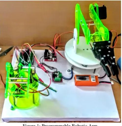
is the optimal alternative for this application. Four different axis of rotation: One at the EOAT to keep the payload parallel to the ground, two at the arm to extend it, and one at the base to rotate it. The axis design contributed to the robot’s short cycle time, low weight, low complexity, and ability to hold a higher payload of 110kgs, well above the weight of the scrap blocks. Ample operating area: Because of the long reach of the robot, this has a maximum reach of 2400mm from the center of axis 4. This allows the arm the ability to reach all of the objects the robotic arm needs to move, with a very small footprint of 0.73m^2. The robot’s size also allows pallets to be places 20% closer to the robot, when compared to other models of similar size. This is crucial since the working area at Pacific Can The arm control by robotics is very popular in the world of robotics. The essential part of the robotic arm is a programmable micro controller based brick capable of driving basically Two servos & a dc motors design to form an anthropomorphic.Figure 1: Programmable Robotic Arm Robot Arm Control:
(www.rdmodernresearch.com) Volume 4, Issue 1, 2019
28
future scope of the project. Here we use an accelerometer designed by Freescale Semiconductors. The MMA7361L is a low power, low profile capacitive micro-machined accelerometer featuring signal conditioning, a pole low pass filter, temperature compensation, self-test, 0g-Detect which detects linear free fall, and g-Select which allows for the selection. Let's start with the name, H-bridge. Sometimes called a "full bridge" the H-bridge is so named because it has four switching elements at the "corners" of the H and the motor forms the cross bar. The basic bridge is shown in the figure to the right. Of course the letter H doesn't have the top and bottom joined together, but hopefully the picture is clear. The key fact to note is that there are, in theory, four switching elements within the bridge. These four elements are often called, high side left, high side right, low side right, and low side left (when traversing in clockwise order). The switches are turned on in pairs, either high left and lower right, or lower left and high right, but never both switches on the same "side" of the bridge. If both switches on one side of a bridge are turned on it creates a short circuit between the battery plus and battery minus terminals. This phenomena is called shoot through in the Switch-Mode Power Supply (SMPS) literature. If the bridge is sufficiently powerful it will absorb that load and your batteries will simply drain quickly. Usually however the switches in question melt. To power the motor, you turn on two switches that are diagonally opposed. In the picture to the right, imagine that the high side left and low side right switches are turned on. The current flow is shown in green.Controls:
In the manual mode, you can control the arm using a joystick. In the automatic mode, the arm will repeat a sequence of movements over and over again. First, a historical research on robot arms was carried out and the basic information needed to establish the system was obtained. The robot used in the project types with arm joint and can move in 4 axis directions (left and right, up and down) and also can hold and swing motion thanks to the holder on it. The micro controller Arduino Nano is used to provide optimal control of the robot arm. The reason for preferring this micro controller is that it is more accessible to be able to get a solution to a possible error because the open source code is easier to use than the other micro controllers and the number of users is higher. After these studies, detailed information has been obtained about the servo motors to be used. The servomotor is preferred because it can be carried out smoothly in the robot project, the motor can be operated precisely and it must be at high torque. The robot arm, 5 servo motors are formed. Servo motors are numbered from top to bottom in order to explain their tasks because of the excess. Arduino Uno is a micro controller board based on the AT mega 328P. It has 14 digital input/output pins (of which 6 can be used as PWM outputs), 6 analog inputs, a 16 MHz quartz crystal, a USB connection, a power jack and a reset button. It contains everything needed to support the micro controller; simply connect it to a computer with a USB cable or power it with a AC-to-DC adapter or battery to get started.. You can tinker with your UNO without worrying too much about doing something wrong, worst case scenario you can replace the chip for a few dollars and start over again. Typical applications of this include
Robotics: Motion Sensing
3D Gaming: Tilt and Motion Sensing, Event Recorder HDD MP3 Player: free-fall Detection
Laptop PC: free-fall Detection, Anti-Theft
Cell Phone: Image Stability, Text Scroll, Motion Dialing, E-Compass Pedometer: Motion Sensing
PDA: Text Scroll
Navigation and Dead Reckoning: E-Compass Tilt Compensation
The device consists of a surface micro-machined capacitive sensing cell (g-cell) and a signal conditioning ASIC contained in a single package. The sensing element is sealed hermetically at the wafer level using a bulk micro-machined cap wafer. The g-cell is a mechanical structure formed from semiconductor materials (poly-silicon) using semiconductor processes (masking and etching). It can be modeled as a set of beams attached to a movable central mass that move between fixed beams. The movable beams can be deflected from their rest position by subjecting the system to acceleration. As the beams attached to the central mass move, the distance from them to the fixed beams on one side will increase by the same amount that the distance to the fixed beams on the other side decreases. The change in distance is a measure of acceleration. The g-cell beams form two back-to-back capacitors. As the center beam moves with acceleration, the distance between the beams changes and each capacitor's value will change, (C = Aε/D). Where A is the area of the beam, ε is the dielectric constant, and D is the distance between the beam The ASIC uses switched capacitor techniques to measure the g-cell capacitors and extract the acceleration data from the difference between the two capacitors. The ASIC also signal conditions and filters (switched capacitor) the signal, providing a high level output voltage that is ratio metric and proportional to acceleration. Figure 2 shows the simplified functional block diagram of an accelerometer.
Android App:
(www.rdmodernresearch.com) Volume 4, Issue 1, 2019
29
would be a great idea to read a bit about robotic arms. It would be very unfortunate if you built everything just to find out that your servos is too weak for your arm. To avoid this happening to you, I recommend that you read this. Also, do all your calculations before hand to know the torque you'll need for every servo? Keep in mind that all the specs found on the Internet are very generous.Y. huang et al, on a flat surface like a table a hard cardboard a servo is placed in the middle and glued in place. The degree of rotation is 0 to 180 degrees, which forms the base of the arm. This base forms the main joint on this servo the whole load of other servo was made. So there was a problem initially but then it was fixed tightly with screws and made it. Fig 8 shows how the base forms the bottom part of the robotic arm. Then a small piece of cardboard is placed on the top of the first servo and above it a second servo is placed on this piece and glued it in the place. The servo rotation m just is again 0 to 180 degree rotation. This servo forms the joint of the arm thus forming the second base of robotic arm. That is how the second servo is placed on the second servo. Each Servo is necessary for another servo joint forming a scaled hand so that arms remains stable and we can use pick and place the object easily. Then for the joint we take few types of cardboard and cut them into 3cm*11cm pieces. Making sure the piece is not softened otherwise it will not able to support the servo motor and would fall easily. Cutting a small rectangular hole at one end (leaving 0.8cm from bottom) that is just enough to fit another servo in it which would form the base of the fourth servo.
T. Asakura et al, The third servo is fitted and gear tightly with screws and by glue. Then fitting the third servo in the first hole now the fourth and the last servo is glued at the edge of another piece that is made of another cardboard piece with length 8cm, 3cm, 4cm, 1cm. With this we connect the third and fourth respectively together and hence we set up as of Fig 11 and this servo forms the main to pick and place device. Now we make a hook so that we can easily pick the objects so for that we cut two pieces of cardboard of length 1cm*7cm and 4cm*5cm gluing them together making it a final grab and then all the joints are glued together and we get a robotic arm ready to connect to the digital pins of Arduino and which can be controlled by the use of the 10k pot. Fig 8 to fig12 show for the one by one step move for arm. Step 1Here the first statement represents the header file for controlling the SERVO MOTOR. Second statement is for naming the servo. Here considering as servo0 as i have used four servo motor. Third statement states where the servo signal pin is connected this must be PWM pin here pin3 for first servo.
M. Haixia et al.., The following are two major challenges and the solutions I chose to manage the situation: Due to the constraints on the XR-4 robotic arm workspace, and the size of the force control device that is large relative to the robotic arm, it was easier to include user interaction in both sub-problems; to put the device in the XR-4 end effector manually instead of programming the robotic arm to pick up the device from a given location. Therefore an intermediate pause was added to the program code to allow the user to attach the force control device to the end effector. Once the device is held in place, the user will trigger a switch on the Mark IV Controller to close the gripper. Similar user interaction is involved to remove the force control device at the end of the tracking procedure. Another issue was that the XR-4 gripper can only apply a limited amount of force onto the object held, for safety purposes to prevent damage to the object. Since the force control device is fairly long, each sliding error between the object and the gripper propagates a bigger error to the tip of the device that writes on the contact surface. This challenge was encountered during the first part of the force control application, when the device would slide slightly under the friction between the tip of the device and the contact surface. The slight shift caused the tip of the device to stray away from the tracking path by a considerable amount. By attaching the external clamp onto the gripper after the force control device is held by the end effector, the sliding error was reduced. Servo motors are a type of electromechanical actuators that do not rotate continuously like DC/AC or stepper motors; rather, they are used to position and hold some object. They are used where continuous rotation is not required so they are not used to drive wheels (unless a servo is modified). In contrast they are used where something is needed to move to particular position and then stopped and hold there. Most common use is to position the rudder of aircrafts and boats etc. The servo can be commanded to rotate to a particular angle (say 30) and then hold its position there. Servos also employ a feedback mechanism, so it can sense an error in its positioning and correct it.
Experimental Work:
(www.rdmodernresearch.com) Volume 4, Issue 1, 2019
30
provide flexibility to the tip of the device during the insertion. When the device is inserted slightly off-centre, the tip would be able to “wriggle” into the hole without causing damage to the insertion device or the mating parts. Furthermore, the tip of the device and the interior side of the hole in the mating part was rounded to allow for smooth contact and entry into the hole. The field is controlled below the knee point of magnetizing saturation curve. At that portion of the curve the MMF linearly varies with excitation current. That means torque developed in the DC motor is directly proportional to the field current below the knee point of magnetizing saturation curve. In my senior design project, I have used the XR-4 robotic arm to demonstrate two applications of robotics in industry; components assembling and using force control to perform tasks such as tracking a given path while maintaining contact with a surface. The insertion control device demonstrated the usefulness of passive compliance devices in assembling tasks by compensating for any misalignment between the mating parts. In addition, performing such tasks using robots avoid the passive repetition of the movement that would bore a person assigned to the task and minimise human errors throughout the process. Meanwhile, the XR-4 robotic arm is able to perform the task continuously without tiring and with minimal errors. The force control device proposed can provide a suitable solution in robotic applications in industry where a constant amount of force onto a surface contact is required to accomplish a task, such as polishing a surface. Requirements for such a task would be impractical for a person to carry out since it is impossible for a person to gauge and maintain the amount of force that is applied onto a surface. Therefore active force feedback control devices are usually used in industries. With the advancement of robotic technology, more tasks are being performed by robots to reduce the execution time and minimise human errors, such as slips caused by exhaustion and negligence. Utilization of robots also reduces downtime by performing a task continuously until it is shut down for maintenance or at the completion of the assigned task.The below figure shows how four potentiometer are fixed Practice is required for rotating the pots accordingly and thus by when the ADC values are from 0-1023 it will match the servo degree of rotation that is from 0 to 180 degree and we get an appropriate output. Thought there was much vibration in the system still. I made use of capacitor 1000micro farad (4) and 100 nano farad do that we can use of it and block the noise and improve the stability of the robotic arm. Remaining two figures shows the individual Robotic arm and the whole circuit it works accordingly when we apply a 5V supply to the system and we get a suitable output. Thus representing how it works accordingly. Still there is a problem of vibration in the system that can reduce in the future enhancement that is maybe we can use high power servo motor and by the help of it vibration can be reduced even the grabbing power is less that it can pick a very heavy object just a lighter object. In future this structure can be modified and made of heavier materials and power servo or either accelerometer or simple ac, dc motors thus we will get a structure that would be able to pick object easily and grab heavy object easily and act like a perfect crane. Figure show the representing whole robotic arm and Although micro controller type PIC is usually used in programming and software field, Arduino has become very popular in the world in recent times. It is based on Arduino’s past wiring and processing projects. Processing is written for non-programming users. Arduino wiring is produced on the basis of the non-programming language. The links of the manipulator can be considered to form a kinematic chain. The business end of the kinematic chain of the manipulator is called the end effectors and it is analogous to the human hand. The end effectors can be designed to perform any desired task such as welding, gripping, spinning etc., depending on the application. The robot arms can be autonomous or controlled manually and can be used to perform a variety.
Result:
(www.rdmodernresearch.com) Volume 4, Issue 1, 2019
31
Conclusion:Due to the growing demand for natural Human Machine Interfaces and automaton intuitive programming platforms, a robotic system that permits users to manage AN industrial automation using arm gestures and postures was planned. Two 3-axis accelerometers were be the input devices of this system, capturing the human arms behaviors. When compared with alternative common input devices, particularly the teach pendant, this approach mistreatment accelerometer is additional intuitive and straightforward to figure, besides giving the likelihood to control a automaton by wireless suggests that. mistreatment this technique, a no expert robot applied scientist will management an automaton quickly during a natural method. The low worth and short set time area unit alternative advantages of the system. Still the irresponsibleness of the system is a vital limitation to think about. The ANN’s shown to be an honest option to acknowledge gestures and postures, presenting a mean of ninety-two of correctly recognized gestures and postures. The system has a very good response time is another necessary issue. Future work can devolve on the development of the average of properly recognized gestures. One approach might be the implementation of a gyro into the system, in order to separate the acceleration because of gravity from the inertial acceleration. the employment of additional accelerometers attached to the arms is another chance. The Arduino has a very good response time and later the same system can be upto raspberry pi in future and the same is implemented on proteus design tool. Finally, the system was first build on a bread board and the values area calculated the same values were used in the code to see the difference in the of the robotic arm.
References:
1. Y. Huang, L. Dong, X. Wang, F. Gao, Y. Liu, M. Minami, and T. Asakura, “Development of a new type of machining robot- a new type of driving mechanism,” in Intelligent Processing Systems, 1997. ICIPS’97.1997 IEEE International Conference on, vol. 2. IEEE, 1997, pp. 1256– 1259.
2. Z. Kuijing, C. Pei, and M. Haixia, “Basic pose control algorithm of 5- dof hybrid robotic arm suitable for table tennis robot,” in Control Conference (CCC), 2010 29th Chinese. IEEE, 2010, pp. 3728
3. Bejo, W. Pora, and H. Kunieda, “Development of a 6-axis robotic arm controller implemented on a low cost microcontroller,” in Electrical Engineering /Electronics, Computer, Telecommunications and Information Technology, 2009. International Conference on, Vol. 1. IEEE, 2009,