ISSN: 1992-8645 www.jatit.org E-ISSN: 1817-3195
2458
1. INTRODUCTION
The demands for internet access,
telecommunications and broadband services are the
acknowledged forces driving the global
requirement for higher and higher light-wave transmission capacity. Dense wavelength division multiplexing (DWDM) has vastly increased the amount of digital traffic, which a fiber can carry, but allowing more than one wavelength of light in the same fiber. DWDM is firmly established as the technology for long haul, large capacity networks and its use is now spreading throughout the metropolitan and access networks. [5]
Laser Diodes (called LD), Luminescent Diodes, Edge emitting LDs and others are used as a luminescent source for optical communication. The design of source-fiber coupling is often guided by maximizing the optical power coupled into the fiber and by relaxing the fiber-source alignment tolerances. Many of those fiber optic designs are susceptible to optical back-reflections from the fiber resulting in not only reduced coupling efficiency but also an increased optical noise of the signal. [5]-[1]-[7]
However, in order for light to enter into an optical fiber, which is the optical transmission path,
coupling is generally performed by aligning the end of an optical fiber with the luminescent surface. However, due to a considerable divergence in the angle of emission light from the luminescent surface, the coupling efficiency with optical fibers is poor. Consequently, there is a method to improve light entrance into the optical fiber by inserting a lens to improve coupling efficiency and focusing of the light. [1]
Practical lenses for fibers are usually small optical ball lenses or gradient index lenses which are commercially available.
As mentioned, the optical power-launching is based on centering a flat fiber end face directly over the light source as close to it as possible. If the source emitting area is larger than the fiber-core area, then the resulting optical power coupled into the fiber is the maximum that can be achieved. This is a result of fundamental energy and radiance conservation
principles (also known as the law of brightness).
However, if the emitting area of the source is smaller than the core area, a miniature lens may be placed between the source and the fiber to improve the power-coupling efficiency. The function of the Microlens is to magnify the emitting area of the source to match exactly the core area of the fiber end face. If the emitting area is increased by a
magnification factor M, the solid angle within
POSSIBLE LENSING SCHEMES FOR FIBER-OPTIC COUPLING
IMPROVEMENT
1Zaid Ahmed Aljawary, 2Mohammed Ameer Alrwas,3Mohammed Khazal Rashad
1 Faculty of Science and Technology, University of Human Development / Sulaymaniyah, Iraq
2 Faculty of Electrical Eng. Universiti Teknologi Malaysia (UTM) / Johor. Malaysia.
3 Business Administration, Kurdistan technical institute / Sulaymaniyah, Iraq
1[email protected] , 2 [email protected]3[email protected]
ABSTRACT
Integrated coupling between the laser source (such as laser diodes, LD’s) and single-mode fibers (SMFs) are one of the most important and fundamental techniques of optical communications. Integrating lenses in source-fiber and fiber-detector receivers was found a great efficiency enhancement way. Meanwhile, on the other hand Lensed fibers have desirable features of the coupling scheme over ordinary Micro-Lenses, such as compactness, simplicity, stability, and freedom from bulky sizes. Three ways of lens coupling schemes are mentioned. Using a micro - lens, then other ways using lensed fiber-ends to achieve efficient coupling of an optical fiber with a light source from a side and detector on the other side. These scheme findings could guide the evolution of a mass-produced at a low price in comparison to the other complex technical ways that’ll achieve not more than 5% higher coupling efficiency.
2459 which optical power is coupled to the fiber from the LED is increased by the same factor. [2]
However, despite Microlenses compact size, they are relatively large compared to the fiber presenting a number of alignment difficulties when incorporated into integrated systems. Tedious methods of fabricating such lenses include polishing the fiber end and melting, although the results are often less than desirable. There’s a need for micro-optical lenses on fiber tips that are commensurate with the fiber dimensions such that they don’t make a sizable contribution to the overall optical component. [3]
The large future optical networks implementation will induce a growing demand for optical data transmission systems. So, the development of low cost, high-density packaged interconnection devices is therefore essential. [7]
Using Microlense technique will be introduced followed by other different ways of fiber-end
lensing. All for enhancing (long haul
[image:2.612.89.300.398.559.2]communications) as long as they are heavily demanded and has been the requirement of nowadays communication speeds.
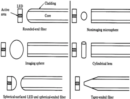
Figure 1: examples of possible lensing schemes used to improve coupling efficiency
Several possible lensing schemes can be introduced
and shown in Fig.1. These include a rounded-end
fiber, a small glass sphere (non imaging microsphere) in contact with both the fiber and the source, a larger spherical lens used to image the source on the core area of the fiber end, a cylindrical lens generally formed from a short section of fiber, a system consisting of a spherical-surfaced LED and a spherical ended fiber, and a taper-ended fiber.
Although these techniques can improve the source-to-fiber coupling efficiency, they also create additional complexities. One problem is that the lens size is similar to the source and fiber-core dimensions, which introduces fabrication and
handlingdifficulties.
In the event of the taper-ended fiber, the mechanical alignment must be packed out with greater precision since the coupling efficiency becomes a more sharply peaked function of the spatial alignment. However, alignment tolerances are increased for other types of lensing systems. Different strategies have been supplied over the article attempting to compare and determine the best strategy to achieve efficient coupling of an optical fiber with a light from both sides. The report is coordinated as follows: in section 1, we give an intro to the importance of coupling scheme over the performance of terminal to end connection depending on different standards. In section 2 and 3, possible type of lensing has been discussed in details with analysis and dissection. In the end, the conclusion is given in section 5 representing a comparison between all scheme’s types.
2. LENSINGSCHIMETYPE
A-FIRST LENSING TECHNIQUE
Non-imaging Microsphere:
One of the most efficient lensing methods is the use of a non-imaging microsphere. Its use for a surface
emitter will firstly be examined, as shown in Fig. 2.
Then the following practical assumptions are made: the spherical lens has a refractive index of about
2.0, the outside medium is air (n = 1.0), and the
emitting area is circular.
To collimate the output from the LED, the emitting surface should be located at the focal point of the lens. The focal point can be found from the gaussian lens formula:
(1)
where s and q are the object and image distances,
respectively, as measured from the lens surface, n is
the refractive index of the lens, n' is the refractive
index of the outside medium, and r is the radius of
curvature of the lens surface. [2]
2460
1. Light travels from left to right.
2. Object distances are measured as positive to the
left of a vertex and negative to the right.
3. Image distances are measured as positive to the
right of a vertex and negative to the left.
4. All convex surfaces encountered by the light
[image:3.612.61.304.199.296.2]have a positive radius of curvature, and concave surfaces have a negative radius.
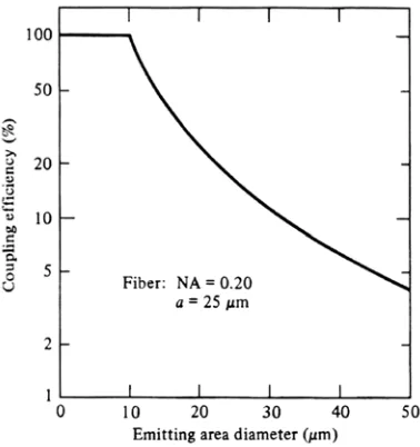
[image:3.612.99.288.347.548.2]Figure 2: Schematic diagram of LED emitter with microsphere lens
Figure 3: Theoretical coupling efficiency for surface emitting LED as a function of emitting diameter.
Thus, the focal point is located on the lens surface
at point A. (This, of course, changes if the refractive
index of the sphere is not equal to 2.0.) Placing the LED close to the lens surface thus results in a
magnification M of the emitting area. This is given
by the ratio of the cross-sectional area of the lens to that of the emitting area:
(2)
It has been shown that, with the lens, the optical
power PL that can be coupled into a full aperture
angle 2θ is given by:
(3)
Where Ps is the total output power of the LED
without lens. The theoretical coupling efficiency that can be achieved is based on energy and radiance conservation principles. This efficiency is usually determined by the size of the fiber. For a
fiber of radius a and numerical aperture NA, the
maximum coupling efficiency η max is given by:
(4) Thus, when the radius of the emitting area is larger than the fiber radius, no improvement in coupling efficiency is possible with a lens. In this case, the best coupling efficiency is achieved by a direct-butt method.
Based on Eq. (4), the theoretical coupling efficiency as a function of the emitting diameter is
shown in Fig. 3 for a fiber with a numerical
aperture of 0.20 and 50-µm core diameter. [2]
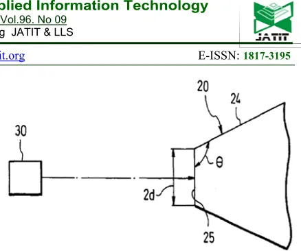
Figure 4A: Front view of a tip end portion of one embodiment of a lensed optical fiber in accordance with
[image:3.612.334.497.367.508.2]the present invention
[image:3.612.319.514.533.703.2]2461 B-SECOND LENSING TECHNIQUE
The present technique provides a lensed optical fiber in which a lens is formed at the tip end of the optical fiber having a core and a cladding, characterized in having a wedge shape with two slant portions symmetrical with respect to the axis of the core and a plane portion perpendicular to the axis of the core.
The lensed optical fiber having the tip end portion of the aforementioned shape has a high optical coupling efficiency. Also, since the shape of this tip end portion is simply formed by three planes, the lensed optical fiber can easily be fabricated with high accuracy and high yield.
Also, inspection of the external form can be made easily. Preferably, an angle between the slant
portion and the plane portion is set at 110o to 170o,
and the distance between two intersecting lines on which the slant portion and the plane portion
intersect with each other is set at 1 to 4µm.
Thereby, the lensed optical fiber in accordance with the present technique achieves an efficiency of 40% or higher of optical coupling with a light source. [4]
Description:
FIG. 4A and FIG. 4B are a front view and a side view, respectively, of a tip end portion of one
embodiment of a lensed optical fiber 20. In the
figures, an optical fiber 21 has a core 22 with a
circular cross-sectional shape and a cladding 23.
The tip end portion of the optical fiber 21 is formed
with a lens 26 comprising a wedge-shaped portion
formed by two slant portions 24 which are
symmetrical with respect to a core axis Ac and a
plane portion 25 which is perpendicular to the core
axis Ac. An angle which the slant portions 24 make
with the plane portion 25 is taken as θ, and a
distance between the two points at which the slant
portions 24 and the plane portion 25 intersect with
each other is taken as 2d. The aforementioned
lensed optical fiber 20 was manufactured by a
[image:4.612.309.528.38.221.2]fabrication procedure as described next.
Figure 5: View for measurement of optical coupling efficiency of the above embodiment
Fabrication:
First, the tip end of the optical fiber 21 was cleaved
to form the plane portion 25 which is perpendicular
to the core axis Ac. Next, the optical fiber 21 was
polished while an angle between a flat plate
polishing machine and the core axis Ac was kept at
a desired angle (θ-90°) using a jig. By this polishing
process, the tip end of the optical fiber 21 could be
formed into the wedge-shaped lens 26. As
described above, the lensed optical fiber 20 of this
embodiment can be manufactured by cleaving the tip end of the optical fiber to form the plane portion
25 and by polishing the slant portions 24 at the tip
end of the optical fiber 21 by onetime angle control.
For the lensed optical fiber 20, therefore, the
fabrication process is very simple, the yield is increased easily, and the fabrication cost is
decreased. For the lensed optical fiber 20, the
optical coupling efficiency was evaluated under the
conditions shown in FIG. 5.
A laser diode, for example, having a generating
wavelength of 0.98 µm at the center was used as a
light source 30, and the intensity distribution (mode
field) pattern of emitted light from the light source
30 was made an ellipse having a major axis of
4.8µm and a minor axis length of 1µm.
Also, the mode field pattern of the optical fiber 21
constituting the lensed optical fiber 20 was made a
circle having a diameter of 6.0µm. Here, the
distance between the light source 30 and the lensed
optical fiber 20 was made the optimum distance at
which the highest optical coupling efficiency can be
obtained, for example, 10µm, and the minor axis
direction of the mode field pattern of the light
source 30 was made a direction perpendicular to the
direction of a line connecting the two points at
which the slant portions 24 and the plane portion 25
2462 Under conditions before, the efficiency of optical
coupling with the light source 30 was evaluated by
changing the angle θ between the slant portion 24
and the plane portion 25 with the distance between
the two points at which the slant portions 24 and
the plane portion 25 intersect with each other being
used as a parameter.
The results are shown in FIG. 6, in which the
abscissa represents (180-θ) and the ordinate represents the coupling efficiency.
Here, the optical coupling efficiency was obtained
from P2/P1, where P1 is the whole power of light
emitted from the light source 30, and P2 is the
[image:5.612.94.296.271.451.2]power of light incident on the optical fiber. [4]
Figure 6: Characteristic diagram showing the relationship between an angle θ which a slant portion
[image:5.612.318.518.553.713.2]makes with a plane portion and the optical coupling efficiency for the above embodiment
Figure 7: Perspective view of a conventional lensed optical fiber
As seen from FIG. 6, in the range of 1.0 to 4.0µm
of the distance 2d and 110 to 170° of the angle θ (in
the figure, (180-θ)=10 to 70°), an efficiency of 40% or higher of optical coupling with the light source
30 was obtained. In particular, in the case where
2d=2.0µm and θ=140 to 150° ((180-θ) = 30 to 40°),
an optical coupling efficiency as high as 90% was obtained. As a comparative example, the optical coupling efficiency of a lensed optical fiber, whose tip end portion was not of a planar shape
perpendicular to the core axis Ac but instead which
had a lens 2 as shown in FIG. 7, was measured
under the aforementioned conditions. In this case, an optical coupling efficiency of 97% at a maximum was obtained. Thus, the lensed optical fiber of the present invention exhibits a high optical coupling efficiency which is by no means inferior to the comparative example. Considering the high workability of the present invention, an excellent lensed optical fiber, which can be mass-produced at a low cost can be provided. [4]
C-THIRD LENSING TECHNIQUE
RECENTLY, there has been a great deal of interest in the use of plastic optical fiber (POF) for short-distance communications, premise networks, and computer interconnections. This is due to several advantages of the POFs over glass optical fibers, i.e., ease of connection, mechanical flexibility, light weight, and ease of material processing and fabrication. Studies on perfluorinated graded-index POF have improved the propagation loss in the wavelength range from 650 to 1300 nm and have presented high-speed rate performance over 10Gb/s.
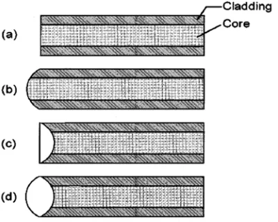
2463 Figure 8: Configurations of the plastic optical fibers (a) flat end, (b) rounded end, (c) planoconvex-lens end, and
[image:6.612.319.515.280.374.2](d) biconvex-lens end.
Figure 9: Schematic of the fixture used for connecting the concave-end fiber to the light source or detector with a
high-index medium between the two.
fiber and of the fiber emission to the detector because they are significant parts of the power budget in the system.
In the case of the flat fiber end, the maximum coupling efficiency can be obtained by positioning the fiber end very close to the source or detector facet. Unfortunately, this poses the risk of striking the fiber against the devices during the assembly process. This technique also allows back reflections to the source, which produce noise at the device output and cause performance degradation in high-speed transmission systems. In the application of the POF, various possible sources exist, such as a vertical cavity surface emitting laser, an edge-emitting laser, and a light-edge-emitting diode as mentioned before. The flat fiber end introduces a limited acceptance angle with minimum working distance, in spite of the easy alignment of large-size cores.
Several ways of forming the lens-like structure directly on the fiber end are preferred in consideration of better mechanical stability, simplicity of fabrication, ease of packaging, and economical performance. [6]
Configuration: -
Fig. 8 schematically shows the several types of fiber-end structures considered in this article. Conventional structures are represented by the flat
and the rounded ends, as shown in Fig. 8(a) and
(b), respectively. The proposed lensed-end fiber
configurations in Fig. 8(c) and (d) have high-index
lenses that are formed by surface tension in the concave ends. The filled lens is automatically adjusted to the core of the fiber and can gather a large amount of light from the source, and, of benefit for detectors, it can focus the transmitted light on the detector. Using such a coupling scheme results in a long working distance because the input and output light can efficiently be converged by the end-lens refraction, which is particularly effective
in low-index fibers. As shown in Fig. 9, the
[image:6.612.322.508.441.601.2]concave end itself presents another advantage when the fiber end is sealed with an optical adhesive to the light source or detector.
Figure 10: Schematic diagram of the optical coupling scheme using proposed
lensed-end configuration for the plastic optical fiber.
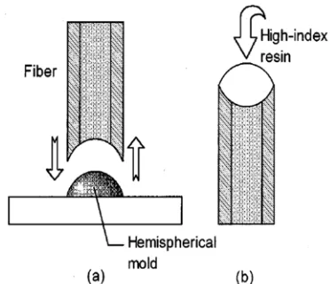
Figure 11: Outline of the procedure for fabricating the lens on the fiber end. (a) Molding with the hemispherical
mold. (b) Filling up the high-index resin on the concave end of the fiber.
2464 The cross section of the lensed end in the
graded-index POF is shown in Fig. 10. The parameters of
the end lens are defined by no as the refractive
index, L as the thickness, and r1 and r2 as the radii
of the curvatures. We assume a graded-index fiber with a clad power-law profile defined by
(5) Where n1 and n2 are the refractive indexes on the core axis and in the cladding, respectively, is the
radius of the core, and x is the ray distance from the
axis. The relative index difference Δ is defined by
(6)
In (5), is the profile exponent that characterizes the refractive index profile. The optimal index profile for the perfluorinated POF is nearly a parabolic
profile, which was found to be q≈2 to enhance
high-bandwidth transmission. [6] Fabrication: -
We used the perfluorinated graded-index POF which had a graded index core of ~125µm diameter, a cladding of ~235µm diameter, and a 500µm outer reinforcement.
[image:7.612.314.538.47.204.2]The core of the POF is based on CYTOP (Asahi Glass, Tokyo, Japan), which is a cyclic polymer of perfluoro- butenyl-vinylether with a radially variable doping to attain the desired refractive index distribution. The cladding is also made of CYTOP without doping. The index profile is approximately parabolic, with a core axial index of 1.354 and a cladding index of 1.342, which yield a theoretical numerical aperture (NA) of 0.18.
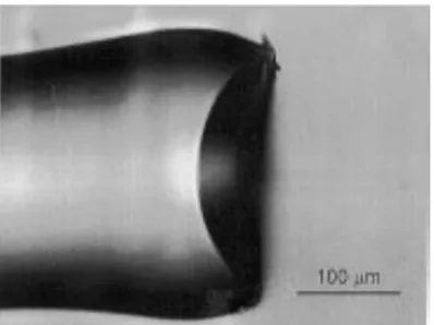
Figure 12: Micrograph of the fabricated fiber end, which is formed into a concave profile through the molding
[image:7.612.96.295.535.684.2]process.
Figure 13: Micrographs of the lensed plastic optical fiber whose end is made up of the resin lens. (a) Oblique side
view. (b) Front view.
In order to prepare the fiber for end-lens fabrication, we removed the acrylic reinforcement layer by soaking the fiber in chloroform for one minute, and then cut the fiber with a blade. As
shown in Fig. 11(a), the cut end of the fiber was
molded by pressing on the hemispherical mold made of nickel. We used a hemispherical mold, which is sufficiently large to form a lens diameter wider than that of the fiber core. The mold temperature was typically set to be 15ºC to 155ºC, which was somewhat below the melting point of the material. The fiber end was formed into the concave shape by the inside tension.
Thus the radius of concave curvature was determined by the radius of the hemispherical
mold. Fig. 12 shows a typical concave shape of the
molded fiber end. The curvature radius was 160 to 170µm, and the depth of the concavity was typically 50 to 60µm. The fabricated concavity was found to have a smooth surface and to directly follow the profile of the metal hemispherical mold, although the edge of the fiber was slightly deformed due to the heating process. For measurements, the opposite end of the fiber was carefully polished using dry lapping films. As
shown in Fig. 11(b), one or two drops of epoxy
resin were applied to the concave end, to a level sufficient to fill it.
2465 Micrographs of the concave end filled with the
epoxy resin are shown in Fig. 13. Using this
method, the resin end lens was automatically positioned on the fiber core, and the lens diameter was nearly the same as the cladding diameter. [6]
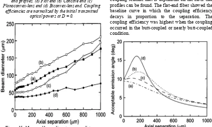
Figure14: Dependence of the coupling efficiency on the axial separation of the plastic optical fibers with various
end profiles. (a) Flat end (b) Concave end (c) Planoconvex-lens end (d) Biconvex-lens end. Coupling
[image:8.612.89.521.417.676.2]efficiencies are normalized by the initial transmitted optical powers at D = 0.
Figure 15: Measured beam diameter versus distance from the processed fiber-end. (a) Flat end. (b) Concave
end. (c) Planoconvex-lens end. (d) Biconvex-lens end.
Results: -
POF ends in the cases of the flat end were evaluated, the concave end, and the two types of resin-filled convex ends.
An 830-nm laser diode through a 6-µm diameter 0.12-NA single-mode fiber (SMF) was used for the evaluation. The output of the SMF served as a light source, and the SMF was mounted on the actuator in order to move the launch position against the endface of the POF of interest. After transmission through 2µm of POF, the output light power at the opposite end of the POF was measured with a combination of an objective lens and a photodetector. [6]
Fig. 14 shows the change in measured coupling efficiency with fiber on-axis location. To make a simple metric of the magnitude of the variations, the coupling efficiency was measured as a ratio of the power transmitted when the fiber end faces were detached, to the power transmitted with the proximate coaxial alignment. The typical values of the transmittance through the examined fibers are 70% to 90%.
The coupling loss was likely related to the reflection at the fiber end due to surface roughness and Fresnel reflection.
From the results in Fig. 15, clear evidence of the
coupling scheme that is dependent on the fiber-end profiles can be found. The flat-end fiber showed the baseline curve in which the coupling efficiency decays in proportion to the separation. The coupling efficiency was highest when the coupling occurred in the butt-coupled or nearly butt-coupled condition.
Figure 16: Dependence of the acceptable emission angle on the axial displacement between the light source and the fiber endface for various lensed fibers (a) Flat end (b)
2466 Conversely, the concave end just filled with the resin, i.e., the planoconvex-lens end, showed a gradual decay in coupling efficiency over a separation of ~400µm. In the case of the concave end overfilled with resin, i.e., the biconvex-lens end, the coupling efficiency increased to its maximum at a working distance of 150µm. It exhibited the longitudinal tolerance of ±150µm at 0.5 dB less than the maximum. For reference, the coupling efficiency was also measured with a vacant concave-end fiber. In this case, the output power was rapidly decreased as we moved the launch position away from the POF endface. These results of coupling efficiency on the various
fiber ends are analogous to those shown in Fig. 16.
This means that the acceptable emission angle is comparable to experiments performed with coupling efficiency as affected by working distance. The output optical field of the lensed end was found to be distinct from that generated by the fiber without a lens. The laser light at 830 nm was launched into the polished end of the POF and the output end of the POF was formed into various profiles.
Fig. 15 shows how the measured beam diameter varies with distance from the output lensed end. The beam diameter was evaluated by the full-width at half-maximum. The beam diameters of the convex-lens ends did not increase over a separation of ~100µm, while in contrast, the flat end and the concave end spread the light out linearly.
These results demonstrate that the convex-lens structures were responsible for the beam narrowing. The biconvex-lens end POF showed the smallest emission angle so that the beam did not diverge at ~200µm separation from the fiber end face and maintained a narrow size in a still larger separation. Although the geometrical optics suggested that the focal length was approximately 200µm for the measured profile of the biconvex-lens end, the convergence of the emitted beam could not apparently be observed in the experiment. This was primarily due to the multimode propagation in the POF. [6]
3. ANALYSISANDDISCUSSIONOF FINDINGS
Firstly, coupling is a more serious matter in high speed and long-distance transmission systems than in normal low speed short distance applications, so it’s being taken care of for being an effective cause of the total optical systems losses in serious data
transmission cases. Mainly, two kinds of lensing techniques are available.
Technique one which introduced a conventional way of including a micro-lens within the system having different shapes which were illustrated before, rounded-end fiber, a small glass sphere (non- imaging microsphere).. etc.
From analyzing the coupling efficiency equations, it has been found that when the radius of the emitting area is larger than the fiber radius, no improvement in coupling efficiency is possible with a lens.
Due to sizing and alignment complexities, other technique was introduced in (Technique two and three) in which the fiber end has to be reshaped into a desired form in a sense that it matches the other side for optimal coupling achievement.
Technique two was a successful practical way of wedging the fiber end and polishing it for softness. The lensed optical fiber of this case has achieved a maximum optical coupling efficiency of 90%
which is inferior to the comparative example in Fig.
7 which had an ending not of a planar shape that
could achieve a coupling efficiency of 97%. So, considering the workability of this method, it’s high, and can be mass-produced at a low cost in comparison to the other complex technical ways that’ll achieve not more than 5-7% higher coupling efficiency.
Technique three was a good practical way of shaping POF using a resin lens filled in the concave end of the fiber. It’s a little more complicated than the previous technique but the fabrication method
eliminates the requirement for additional
components and assembly processes. The fabrication process is also mentioned in details. Two important things one should take care of during this coupling technique, the axial separation that’ll affect the coupling efficiency directly as seen
from Fig. 14 and axial displacement between the
fiber end and the source that affects the acceptance
angle depends on which is also shown in Fig. 16.
2467 subassembly module and for reducing the back reflections.
Also, the light beam was kept narrow in a still large separation in comparison with others which a small spot will provide a relatively large tolerance for transverse misalignment to the limited detector windows.
4.CONCLUSION
The most powerful lensing technique among all was found to be the third one, which outperformed the others in coupling efficiency results as seen in graphs instead of some complications, but all were for reducing back reflections and ensuring the best coupling to be done.
The most practical one among them to use was introduced in the second technique that could easily be mass produced with a very good coupling efficiency acceptable to a wide range of applications.
Meanwhile the first technique was using the same concept but physically different in introducing the lens that lead this method to be impractical in manufacturing for high precision alignment requirement which is not common in mass production. And has a coupling efficiency highly dependent on the emitting device area.
There are various kinds of lensing techniques that can be introduced to the fiber in various shapes, alignments, and different substances and polymers can do the job. But the main concept of enhancing the coupling efficiency , the data needs attention over performance , lies on four points, first, to reduce the light dispersion in the air and focusing the majority or most of it into the fiber, second, widening the acceptance angle for facilitating the coupling process, third, reduce the back reflections (Fresnel back reflections) due to surface roughness to ensure that the beam is totally penetrated into the lens end of the fiber and this is done by lensing, fourth, ensuring the distance between the source and fiber to be as much as possible to own a good tolerance to the distance misalignment that may happen during the manufacturing process.
As better as these factors could be achieved as better as the resulting coupling efficiency can also be achieved.
Due to the limitation of resources and the laboratory equipment’s to repeat most of the measurement in different size and manner of fiber optic the lensing could give more honest answers.
REFERENCES:
[1] Takuji Tsushima, Michitomo Shibutani,
“Optical Fiber with Lens and Method Of
Manufacturing the Same”, United States Patent
Patent No.: 5,845,024. Date of Patent: 1
December 1998.
[2] Keiser, G. (2000). Optical Fiber
Communications, McGraw Hill.
[3] John Canning, Kristy Sommer, Shane
Huntington, Adrian Carter, “Silica based Fiber
Fresnel lens”, 1 December 2001, Elsevier
Science.
[4] Yuichiro Irie; Toshio Kimura, “LENSED
OPTICAL FIBER”, United States Patent,
Patent No.: US 6,317,550 B2, Date of Patent: Nov. 13 2001.
[5] S. K. Mondal, Frank G. Shi, “Novel
lensed-fiber offset coupling scheme to reduce reflected intensity noise in optimizing Carrier
to Noise ratio”, 1 December 2001, Elsevier
Science.
[6] Hajime Sakata, “Lensed Plastic Optical Fiber
Employing Concave End Filled With
High-Index Resin”, IEEE Journal Of Lightwave
Technology, VOL. 20, NO. 4, APRIL 2002.
[7] Jr-Yun Hua, Che-Ping Linb, Shih-Yu Hungb,
Hsiharng Yangc, Ching-Kong Chao, “Semi-ellipsoid microlens simulation and fabrication for enhancing optical fiber coupling