Encoding & Decoding of Low Density Parity Check
Codes using Binary Eraser Channel Method
Panchakshari Awaje1 , D.P.Rathod2
1,2
Electrical Engineering Department, VJTI, Mumbai. India.
Abstract: Now a days, Low Density Parity Check Codes (LDPC) have fascinating tremendous research interest because of their efficient error-correcting performance and highly decoding scheme. In this paper, the parity check matrix (H) is constructed using identity seed method and decodes the code using binary eraser channel method. After this parity check matrix, H is converted into systematic parity check matrix and systematic H matrix is converted to standard Generator matrix (G). The main advantage of the parity check matrix is the decoder can correct all single-bit errors.
Keywords: Low density parity check (LDPC); Binary Eraser channel (BEC); Parity check Matrix (H), Generator matrix (G).
I. INTRODUCTION
Low-density parity-check (LDPC) codes are introduced by Robert Gallagher in 1962 at their Ph.D. thesis in MIT. These codes are neglected for more than thirty to thirty-five years because of hardware complexity at that time. These codes are rediscovered by Mackay and Neal. As their name suggests, LDPC codes are forward error correcting codes with parity-check matrices that contain only a very small number of non-zero entries Low-density parity check codes uses generator matrix G in an encoder and parity check matrix H in a decoder. The advantage of LDPC codes is to correct all single bits errors.
The parity check matrix contains M rows and N columns, where M represents check nodes and N represent variable nodes. This matrix is based on different construction techniques. Information bits are based on check nodes (M) and bits in the code word are based on variable nodes (N). Matrix H contains only a small no of ones and large zeros. Due to large no of zeros, in the matrix, the matrix becomes sparse. If there is the same number of ones in columns and different no of ones in rows, the matrix is called regular. Otherwise, the parity check matrix is irregular. The biggest difference between LDPC codes and classical block codes is in decoding method.
Panchakshari Awaje is M.Tech (Electronics and Telecommunication) student of Veermata Jijabai Technological Institute (VJTI), Mumbai – 400019, INDIA (phone: +91-8983439803; e-mail: [email protected]).
D. P. Rathod. is working as a Professor in Electrical Engineering Department, Veermata Jijabai Technological Institute (VJTI), Mumbai- 400019, INDIA. (E-mail: [email protected]).
Classical block codes are generally decoded with Maximum likelihood (ML) decoding algorithms and LDPC codes, however, are decoded iteratively using a graphical Representation called as tanner graph of their parity-check matrix.
LDPC codes are used in many applications requiring reliable and highly efficient information transfer over channels. These codes have been used in the digital video broadcasting (DVB) standard and are being seriously considered in various real-life applications such as magnetic storage, 10 GB Ethernet, and high-throughput wireless local area network.
II. PROPOSED METHODOLOGY
Constructing LDPC codes is a backward process, starting by constructing the H matrix with dimensions of N × K. there are different method to construct parity check matrix.
Following are the different properties of the low Density parity check matrix to fulfill the requirement: To make matrix spares (i.e. matrix contains small no of ones and large no of zeros.)
To remove short cycle 4 with girth 6 or 8.
To construct H matrix either regular or irregular method.
A. Construction of LDPC Code using Identity Seed Method 1) Algorithm:
b) Calculate to girth of the matrix, it should be greater than six.
c) Replace each zero by zero matrixes and one by identity matrix.
d) The girth of new matrix is same as base matrix.
e) The size of the new matrix is depends on replacement of zero or identity matrix.
f) Obtained new large size sparse matrix whose girth is same as base matrix.
B. Flowchart
Consider a (2, 4)-regular code of base parity check matrix having size (8× 4).
1 1 1 0 0 1 0 0
1 0 0 1 1 0 1 0
0 1 0 1 0 1 0 1
0 0 1 0 1 0 1 0
b
H
This matrix defines the regular LDPC code having length N= 8 with data rate R= 1/2. We want to construct a regular code with length N = 16 of the same rate, thus we define I2 and O2 by:
Start
Input n & k
Initialize matrices
Inter weight of rows & columns
Display parity check matrix
If weight of rows & colums= 0 or 1
Replace 0=zero matrix & 1=identity matrix
New H matrix size= mn*mk
1 0 2
0 1
I
0 0 2
0 0
O
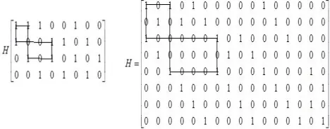
Now replace each 1 by I2 & 0 by O2 and the new H matrix is:
The matrix represents a (2, 4)-regular LDPC code of length of N = 16, and rate R = 1/2.
[image:4.612.184.418.342.434.2]The girth is defined by counting the straight edges that connect between '1'sstarting and ending with the same 1 entry in the parity check matrix, since the construction of the parity check matrix expands with identity and all zeros matrices. The insertion of identity seed results in new cycles of the same length which keeps the girth equal to the same girth in the base matrix.
Figure 1: A graphical representation of cycles of girth g=8.
III. ENCODING OF LDPC
A. Communication System Block
A code-word C is generated as
C=m*G ……….. (1)
B. To Obtain the Generator Matrix G is as follows
Convert nonsystematic H matrix into systematic ‘H’, then convert systematic ‘H’ to Standard generator matrix forms.
The standard forms of the generator and parity-check matrices for an [n, k] binary linear block code is shown in the table below:
Type of matrices Standard form Dimensions
Generator [Ik P] or [P Ik] K-by-n
Parity- check [PT In-k ] or [In-k PT] (n-k )- by -n
Where I= Identity matrix; P= parity matrix;
1 0 1 0 1 0 0 0 0 0 1 0 0 0 0 0 0 1 0 1 0 1 0 0 0 0 0 1 0 0 0 0 1 0 0 0 0 0 1 0 1 0 0 0 1 0 0 0 0 1 0 0 0 0 0 1 0 1 0 0 0 1 0 0 0 0 1 0 0 0 1 0 0 0 1 0 0 0 1 0 0 0 0 1 0 0 0 1 0 0 0 1 0 0 0 1 0 0 0 0 1 0 0 0 1 0 0 0 1 0 1 0 0 0 0 0 0 1 0 0 0 1 0 0 0 1 0 1 H
LDPC Encoder AWGN Channel
1 0 0 0 0 0 0 0 0 0 0 0 0 0 1 0
0 1 0 0 0 0 0 0 0 0 0 0 0 0 0 1
0 0 1 0 0 0 0 0 1 0 1 0 1 0 0 0
0 0 0 1 0 0 0 0 0 1 0 1 0 1 0 0
0 0 0 0 1 0 0 0 1 0 0 0 1 0 1 0
0 0 0 0 0 1 0 0 0 1 0 0 0 1 0 1
0 0 0 0 0 0 1 0 1 0 0 0 1 0 1 0
0 0 0 0 0 0 0 1 0 1 0 0 0 1 0 1
Hsys
0 0 1 0 1 0 1 0 1 0 0 0 0 0 0 0 0 0 0 1 0 1 0 1 0 1 0 0 0 0 0 0 0 0 1 0 0 0 0 0 0 0 1 0 0 0 0 0 0 0 0 1 0 0 0 0 0 0 0 1 0 0 0 0 0 0 1 0 1 0 1 0 0 0 0 0 1 0 0 0 0 0 0 1 0 1 0 1 0 0 0 0 0 1 0 0 1 0 0 0 1 0 1 0 0 0 0 0 0 0 1 0 0 1 0 0 0 1 0 1 0 0 0 0 0 0 0 1 G
n=16, m=8, then, length of message bits (K): n-m=8; Let K= [0 0 0 0 0 0 0 1].
A cod-word C is obtained from equation [1] is as follows:
0 0 1 0 1 0 1 0 1 0 0 0 0 0 0 0
0 0 0 1 0 1 0 1 0 1 0 0 0 0 0 0
0 0 1 0 0 0 0 0 0 0 1 0 0 0 0 0
0 0 0 1 0 0 0 0 0 0 0 1 0 0 0 0
0 0 0 0 0 0 0 1
0 0 1 0 1 0 1 0 0 0 0 0 1 0 0 0
0 0 0 1 0 1 0 1 0 0 0 0 0 1 0 0
1 0 0 0 1 0 1 0 0 0 0 0 0 0 1 0
0 1 0 0 0 1 0 1 0 0 0 0 0 0 0 1
c
C= [0 1 0 0 0 1 0 1 0 0 0 0 0 0 0 1] To check whether the given code-word is valid or not by uses the formula:
GHT =0………. (2)
IV. DECODING OF LDPC
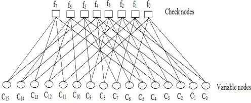
The class of decoding algorithms used to decode LDPC codes is collectively known as message-passing algorithms since their operation can be explained by the passing of messages along the edges of a Tanner graph. The message-passing algorithms are also known as iterative decoding algorithms as the messages pass back and forward between the bit and check nodes iteratively until a result is achieved (or the process halted).
A. Message-Passing on the Binary Erasure Channel
[image:6.612.182.430.150.252.2]On the binary erasure channel (BEC) a transmitted bit is either received correctly or completely erased with some probability ε. Since the bits which are received are always completely correct the task of the decoder is to determine the value of the unknown bits.
Fig 2 Tanner graph representation of LDPC matrix
Let c is sent through an erasure channel and the received vector is:
Y = [0 1 -1 0 0 1 0 1 0 0 -1 0 0 -1 0 1] to recover the erased bits is as follows:
Enter the no of iterations: 8
Y = 0 -1 0 0 0 1 0 1 0 0 -1 0 0 -1 0 1
Y = 0 -1 0 0 0 1 0 1 0 0 -1 0 0 -1 0 1 Y = 0 -1 0 0 0 1 0 1 0 0 -1 0 0 -1 0 1
Y = 0 1 0 0 0 1 0 1 0 0 -1 0 0 -1 0 1 Y = 0 1 0 0 0 1 0 1 0 0 0 0 0 -1 0 1
Y = 0 1 0 0 0 1 0 1 0 0 0 0 0 -1 0 1 Y = 0 1 0 0 0 1 0 1 0 0 0 0 0 0 0 1 Y = 0 1 0 0 0 1 0 1 0 0 0 0 0 0 0 0
After 8th iteration the received correct code word is:
Y= [0 1 0 0 0 1 0 1 0 0 0 0 0 0 0 1] Whether received code is correct or not is verified by using syndrome checking formula:
S=rHT……….(3)
1 0 1 0 0 0 0 0
0 1 0 1 0 0 0 0
1 0 0 0 1 0 0 0
0 1 0 0 0 1 0 0
1 0 0 0 0 0 1 0
0 1 0 0 0 0 0 1
0 0 1 0 1 0 0 0
0 0 0 1 0 1 0 0
0 1 0 0 0 1 0 1 0 0 0 0 0 0 0 1
0 0 1 0 0 0 1 0
0 0 0 1 0 0 0 1
1 0 0 0 1 0 0 0
0 1 0 0 0 1 0 0
0 0 1 0 0 0 1 0
0 0 0 1 0 0 0 1
0 0 0 0 1 0 1 0
0 0 0 0 0 1 0 1
S
V. CONCLUSON
LDPC coding is a forward error correcting coding technique which allows correcting all single bit errors. In this paper, Parity check matrix is constructed using identity seed method. The proposed construction keeps the degree of variable nodes and checks nodes fixed. The insertion of the identity matrices leads to sparser H matrix. The advantage of this construction is reducing the time of decoding process & also reduced power consumption of channel.
REFERENCES
[1] R. G. Gallager, “Low density parity check codes,” IRE Trans. Inform. Theory, vol. IT-8, no.1, pp. 21–28, Jan. 196
[2] D. J. C. MacKey, R. M. Neal, “Near Shannon limit performance of low density parity check codes,” Electronics letters, vol. 32, no.18, pp.1645–1646. [3] R. M. Tanner, “A Recursive Approach to Low Complexity Codes,” IEEE Trans. Inform. Theory, vol. IT-27, no.5, pp. 533–547, Sep. 1981.
[4] S. J. Johnson, “Introducing Low-Density Parity-Check Codes,” unpublished.
[5] T. Richardson, “Error floors of LDPC codes,” in Proc. Annual Allerton Conference on Communication, Control, and Computing, Monticello, IL, pp. 1426-1435, Oct. 2003.
[6] T. Tian, C. Jones, J. Villasenor, and R. D. Wesel, “Construction of irregular ldpc codes with low error floors,” in Proceedings IEEE International Conference on Communications, 2003.
[7] An FPGA Architecture for Low Density Parity Check Codes ,Orlando J. Hernandez and Nathaniel F. Blythe.
[8] Y. Kou, S. Lin and M. Fossorier, "Low-Density Parity-Check Codes Based on Finite Geometries: A Rediscovery and New Results," IEEE Transactions on Information Theory, vol. 47,no.7,November 2001, pp. 2711- 2736.
[9] Zhengya Zhang, Venkat Anantharam,Martin J. Wainwright, and Borivoje Nikolic. "An Efficient 10G BASE-T Ethernet LDPC Decoder Design With Low Error Floors“, IEEE Conference, Australia, July 2016.
[10]Halford, T.R. and K.M. Chugg, “ Enumerating and counting cycles in bipartite graphs”, IEEE Proceedings of the Workshop on Communication Theory, May 5-8, 2004.
[11]S. Lin and D. Costello, Jr., Error Control Coding: Fundamentals and Applications, ser. Prentice-Hall Series in Computer Applications in Electrical Engineering. Englewood Cliffs, N. J. 07632f: Prentice-Hall, Inc., 1983.