5
XI
November 2017
Design Optimisation of a Steering Knuckle
Component Using Conservative Method of Finite
Element Analysis
Ch. Syam Kumar1, B. Kiran Kumar2, J.KanthaRao3, R. Anil Kumar4
1,2. 3
Assistant Professor, Dept. of Mechanical Engineering, Sasi Institute of Technology & Engineering, Tadepalligudem, Andhra Pradesh -534101 ,India.
4
Assistant Professor, Dept. of Mechanical Engineering, Vizag Institute of Technology, Visakhapatnam, Andhra Pradesh -531162, India.
Abstract: The weight of the vehicle is available on rising due to supplementary luxurious and safety features. Steering Knuckle is one of the serious mechanism of vehicle which associations suspension, steering system, wheel hub and brake to the chassis. It undergoes changeable loads subjected to dissimilar conditions, while not touching vehicle steering act and other preferred vehicle characteristics. This paper focuses on optimization of steering knuckle targeting reducing weight as objective function with compulsory strength, frequency and stiffness. In automotive suspension, a steering knuckle is that element which contains the wheel hub or spindle, and attaches to the suspension components. The wheel and tire assembly attach to the hub or spindle of the knuckle where the tire/wheel rotates while being held in a stable plane of motion by the knuckle/suspension assembly. The modeling of this project is done in Creo Parametric 2.0 and the analysis is carried out in Ansys 15.0.
Key Words: Creo Parametric 2.0, Frequency, FEA, Wheel hub, Stiffness, Suspension…...
I. INTRODUCTION
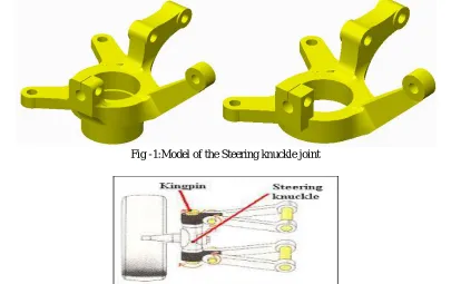
In automotive suspension, a steering knuckle is that part which contains the wheel hub or spindle, and attaches to the suspension components. It is variously called a steering knuckle, spindle, upright or hub, as well. The wheel and tire assembly attach to the hub or spindle of the knuckle where the tire/wheel rotates while being held in a stable plane of motion by the knuckle/suspension assembly.The wheel assembly is attached to the knuckle at its centre point. Note the arm of the knuckle that sticks out, to which the steering mechanism attaches to turn the knuckle and wheel assembly. Steering knuckles come in all shapes and sizes. Their designs differ to fit all sorts of applications and suspension types. However, they can be divided into two main types. One comes with a hub and the other comes with a spindle.ass or weight reduction is becoming important issue in car manufacturing industry. Weight reduction will give substantial impact to fuel efficiency, efforts to reduce emissions and therefore, save environment. Weight can be reduced through several types of technological improvements, such as advances in materials, design and analysis methods, fabrication processes and optimization techniques, etc. Another tool had been developed beside the CAD software which is CAE.
A. Creo Parametric
Creo Parametric is a computer graphics system for modeling various mechanical designs and for performing related design and manufacturing operations. The system uses a 3D solid modeling system as the core, and applies the feature-based, parametric modelling method. In short, Creo Parametric is a feature-based, parametric solid modelling system with many extended design and manufacturing applications
II. METHODOLOGY
The study is on modeling a suspension system and the analysis of its factor of safety, stresses involved and displacement under random loading conditions. CAD models of the suspension system of a vehicle were developed with a 3D modeling software . The fatigue and stress analysis of the models were obtained and compared using FEA with Ansya16 software to optimize for weight reduction.
Due to its large volume production, it is only logical that optimization of the steering knuckle for its weight or volume will result in large-scalesavings. It can alsoachieve the objective of reducing the weight of the vehicle component, thus reducing inertia loads, reducing vehicle weight and improving vehicle performance and fuel economy. So considering automobile development and importance of relative aspect such as fuel consumption, weight, riding quality, and handling, hence development of new material is necessary in the automobile industry. In spite of different configurations of the steering knuckle/spindle assembly for each type of vehicle suspension, the assembly is intended to play a common role in all type, and that is to accommodate the service loading. Mass or weight reduction is becoming important issue in car manufacturing industry. Weight reduction will give substantial impact to fuel efficiency, efforts to reduceemissions and therefore, save environment.
III. MATERIAL SELECTION.
There are several materials used for manufacturing of steering knuckle such as S.G. iron (ductile iron), white cast iron and grey cast iron. But grey cast iron mostly used. Forged steel are most demanding material for this application. Now a day’s automobile industry has put effort to use as S-Glass Epoxy an alternative. Due to low weight of this material, it can reduce fuel consumption and CO2 emission. So as per survey best suited material was Gray Cast Iron alloy. It has low density and compatible yield strength. This material was chosen for designing knuckle by comparing its result with other material.
IV. DESIGN AND FINITE ELEMENT ANALYSIS OF KNUCKLE COMPONENT ASSEMBLY.
The finite element analysis of the suspension system assembly was performed on Ansys Professional in the manner : 1. the design calculation of the system carried out, 2. the modeling of a three-dimensional knuckle system assembly which consist of the hub attached to the wheel, the upper and lower arms and the spring connector, 3. the selection of materials was done based on typical materials used for existing suspension systems and materials that are readily available with good mach inability properties;. 4. the simulation of the model after meshing and the generation of the result on static stress analysis were carried out.
[image:3.612.104.509.462.717.2]Consequently considerable emphasis is placed on computer-aided design requiring the use of multi-body systems analysis software. This software enables many ‘what– if’ scenarios to be tested quickly without the need for a lot of development testing, but they do require sophisticated mathematical models to be developed for various components and sub-systems. There are also other limitations such as cost, weight, packaging space, requirements for robustness and reliability, together with manufacturing, assembly and maintenance constraints to be considered while design and optimization process. In the book ‘The Finite Element Method: Its Basis and Fundamentals’, Zeinkiewicz, Taylor and Zhu explain the concepts behind the mathematical modeling of component under study with emphasis on the mesh generation and mesh relevance parameters
Fig -1:Model of the Steering knuckle joint
Their work is a very thin structure on which the FEA method for the steering knuckle optimization was developed. Creo Parametric was designed to begin where the design engineer begins with features and design criteria. CreoParametric's cascading menus flow in an intuitive manner, providing logical choices and pre-selecting most common options, in addition to short menu descriptions and full on-line help. This makes it simple to learn and utilize even for the most casual user. Expert users employ CreoParametric's "map keys" to combine frequently used commands along with customized menus to exponentially increase their speed in use. Because Creo Parametric provides the ability to sketch directly on the solid model, feature placement is simple and accurate.
V. ANALYSIS OF STEERING KNUCKLE JOINT. A. Analysis of Original Aluminum Steering Knuckle joint:
1) Geometric model
The geometric model for the Original Aluminum Steering Knuckle is as shown in the Fig3.
Fig.3. Geometry of the Original Aluminium Steering Knuckle jointIn the above figure shows
2) Meshed Model:The meshed model for the Original Aluminium Steering Knuckle is as shown in the Fig. 4
Fig.4. Meshed model of the Original Aluminum Steering Knuckle joint
3) Boundary Conditions
The boundary conditions for the Original Aluminum Steering Knuckle joint is as shown in the Fig. 5
4) Deformation: The deformation for the Original Aluminum Steering Knuckle is as shown in the Fig. 6
Fig. 3.6.Deformation of the Original Aluminum Steering Knuckle joint
[image:5.612.126.487.306.459.2]5) Equivalent Stress:The Equivalent Stress for the Original Aluminum Steering Knuckle is as shown in the Fig. 7
Fig.7. Equivalent Stress for the Original Aluminum Steering Knuckle joint
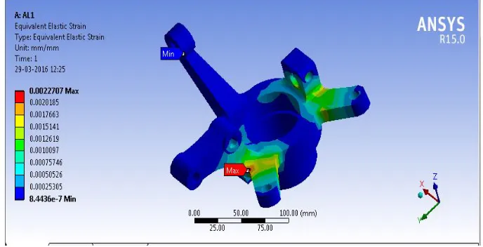
6) Equivalent Elastic Strain:The Equivalent Elastic Strain for the Original Aluminum Steering Knuckle is as shown in the Fig. 8
Fig. 8.Equivalent Elastic Strain for the Original AluminumSteering Knuckle joint
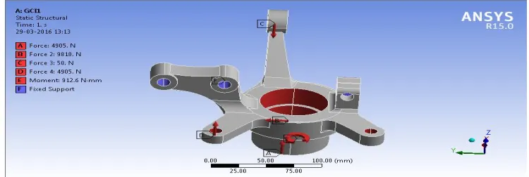
B. Analysis of Grey Cast Iron Steering Knuckle 1) Boundary Conditions
[image:5.612.134.478.500.676.2]Fig. 9.Boundary Conditions of the Grey Cast Iron Steering Knuckle joint.
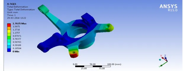
[image:6.612.127.486.246.364.2]2) Deformation:The Deformation for the Grey Cast Iron Steering Knuckle joint is as shown in the Fig. 10
Fig. 10.Deformation of the Grey Cast Iron Steering Knuckle joint
3) Equivalent Stress:The Equivalent Stress for the Grey Cast Iron Steering Knuckle is as shown in the Fig. 11
Fig. 11.Equivalent Stress for the Grey Cast Iron Steering Knuckle joint
6) Equivalent Elastic Strain:
The Equivalent Elastic Strain for the Grey Cast Iron Steering Knuckle is as shown in the Fig. 12
C. Analysis of S-Glass Epoxy Steering Knuckle joint:
[image:7.612.154.463.104.235.2]1) Boundary Conditions:The boundary conditions for the S-Glass Epoxy Steering Knuckle is as shown in the Fig.13.
Fig. 13.Boundary Conditions of the S-Glass Epoxy Steering Knuckle joint.
[image:7.612.150.459.276.396.2]The Deformation for the S-Glass Epoxy Steering Knuckle is as shown in the Fig.14
Fig. 14. Deformation of the S-Glass Epoxy Steering Knuckle
[image:7.612.160.460.441.562.2]3) Equivalent Stress:The Equivalent Stress for the S-Glass Epoxy Steering Knuckle is as shown in the Fig. 15
Fig. 15.Equivalent Stress for the S-Glass Epoxy Steering Knuckle joint.
4) Equivalent Elastic Strain:The Equivalent Elastic Strain for the S-Glass Epoxy Steering Knuckle is as shown in Fig.16.
V. RESULTS AND DISCUSSION
The results for the analysis done on Aluminium Knuckle joint are as shown in the table 1.
S.No Stress
Mpa Strain
Deformation mm Weight Kg 1 158.9
3 0.0022707 0.63609 0.92784
2 172.8
2 0.0025052 0.67619 0.91874
3 156.6
7 0.0022629 0.70905 0.87568
4 148.0
3 0.0021322 0.71191 0.87559
5 170.5
6 0.0024806 0.70906 0.82012
The results for the analysis done on Gray cast-iron Knuckle joint are as shown in the table 2.
The results for the analysis done on S- Glass Epoxy Knuckle joint are as shown in the table 3.
S.NoS.
NO Stress
Mpa Strain
Deformatio n mm
Weight Kg
1 237.86 0.008289
6 1.7635 0.66992
2 271.57 0.009896
6 1.9426 0.66335
3 242.91 0.009567
8 2.0785 0.63226
4 221.82 0.008949
2 2.087 0.63219
5 274.34 0.010864 2.0805 0.59214
Our aim is to reduce the weight of the steering knuckle joint while keeping the stress within the safe limits. Thus from the first results table it is very clear that the fourth model gives us optimized results i.e. less stress value and also less weight. The model is then analyzed using two different materials viz. Gray Cast Iron and S-Glass Epoxy. The results tables clearly indicate that there is a significant amount of weight reduction when we use S-Glass Epoxy material. The stress values are within the safe limits of their respective material properties. Thus we have optimized the steering knuckle joint by shape optimization and also material optimization in ANSYS 15.0
S. No. Stress
Mpa Strain
Deformation mm
Weight Kg
1 159.28 0.0014688 0.41268 2.4117
2 170.32 0.0015941 0.43871 2.3881
3 155.11 0.0014461 0.46037 2.2761
4 146.34 0.0013601 0.46222 2.2759
REFERENCES
[1] PurushottamDumbre, Prof A.K.Mishra, V.S.Aher, Swapnil S. Kulkarni, “Structural Analysis Of Steering Knuckle For Weight Reduction”, International Journal of Advanced Engineering Research and Studies, Int. J. Adv. Engg. Res. Studies/III/III/April-June,2014/86-86.
[2] Kiran S.Bhokare, G.M.Kakandikar, Swapnil S. Kulkarni, “Predicting the Fatigue of Steering Knuckle Arm of a Sport Utility Vehicle While Deploying Analytical Techniques Using CAE”, International Journal of Scientific Research and Management Studies (IJSRMS), Volume 1 Issue 11, pg: 372-381.
[3] Mahesh P. Sharma1, Denish S. Mevawala2, Harsh Joshi3, Devendra A. Patel, “Static Analysis of Steering Knuckle and Its Shape Optimization”, International Conference on Advances in Engineering & Technology, 2014.
[4] EshaanAyyar, Isaac de Souza, Aditya Pravin, SanketTambe, AqleemSiddiqui&NitinGurav, “Selection, Modification and Analysis of Suspension System for an All-Terrain Vehicle”, ISSN : 2319 – 3182, Volume-2, Issue-4, 2013
[5] Wan Mansor Wan Muhamad, EndraSujatmika, Hisham Hamid, &FarisTarlochan, “Design Improvement of Steering Knuckle Component Using Shape Optimization”, International Journal of Advanced Computer Science, Vol. 2, No. 2, pp. 65-69, Feb. 2012.
[6] Nassir S. Al-Arifi, Abu S. Zamani, and Jalaluddin Khan, “Billet Optimization for Steering Knuckle Using Taguchi Methodology”, International Journal of Computer Theory and Engineering, Vol. 3, No. 4, August 2011.
[7] MehrdadZoroufi and Ali Fatemi, “Fatigue Life Comparisons of Competing Manufacturing Processes: A Study of Steering Knuckle”, SAE International, 2003.
[8] Poonam P. Tagade, Anil R. Sahu, H. C. Kutarmare,“Optimization and Finite Element Analysis of Steering Knuckle” International Conference on Quality Up-gradation in Engineering, Science and Technology, ICQUEST, 2015.
[9] ManikA.Patil,Prof.D.S.Chavan,Prof.M.V.Kavade,Umesh S. Ghorpade, “FEA of Tie Rod of Steering System of Car”, International Journal of Application or Innovation in Engineering & Management (IJAIEM), Volume 2, Issue 5, May 2013.
[10] Sharad Kumar Chandrakar, DheerajLalSoni and ShohelGardia, “FEA of A Steering Knuckle for Life Prediction”, International Journal of Engineering Research and Technology.ISSN 0974-3154 Volume 6, Number 5, 2013.
[11] B.Babu, M. Prabhu, P.Dharmaraj, R.Sampath, “Stress Analysis on Steering Knuckle ofthe Automobile Steering System”, IJRET: International Journal of Research in Engineering and Technology, ISSN: 2319-1163 | ISSN: 2321-7308.