HP 9000 Series 500 Computer Systems
HP27140A
Asynchronous 6-Channel Multiplexer
(with Modem Control)
Hewlett-Packard Company Roseville Networks Division 8000 Foothills Boulevard Roseville, California 95678
Hardware Reference Manual
Fli;-
HEWLETT
a:~
PACKARD
Card Assembly: 27140-60001
2
Notice
The information contained in this document is subject to change without notice.
HEWLETI-PACKARD COMPANY MAKES NO WARRAN'IY OF ANY KIND WITH REGARD TO THIS MATERIAL, INCLUDING, BUT NOT LIMITED TO, THE IMPLIED WARRANTIES OF MERCHANT-ABILI'IY AND FITNESS FOR A PARTICULAR PURPOSE. Hewlett-Packard shall not be liable for errors contained herein or for incidental or consequential damages in connection with the furnishing, performance, or use of this material.
Hewlett-Packard assumes no responsibility for the use or reliability of its software on equipment that is not furnished by Hewlett-Packard.
This document contains proprietary information, which is protected by copyright. All rights are reserved. No part of this document may be photocopied, reproduced, or translated into another language without the prior written consent of Hewlett-Packard.
Printing History
New editions are complete revisions of the manual. Update packages, which are issued between editions, contain additional and replacement pages to be merged into the manual by the customer. The dates on the title page change only when a new edition or a new update is published. No information is incorporated into a reprinting unless it appears as a prior update; the edition does not change when an update is incorporated. A software code may be printed before the date; this indicates the version level of the software product at the time the manual or update was issued. Many product updates and fIXes do not require manual changes and, con-versely, manual corrections may be done without accompanying product changes. Therefore, do not expect a one-to-one correspondence between product updates and manual updates.
Edition 1 . . . June 1988 Update 1 . . . October 1988
General
Safety Symbols
''1U,jut,)
I
Caution
I
4
Safety Considerations
This product and related documentation must be reviewed for familiariza-tion with safety markings before operafamiliariza-tion.
Instruction manual symbol: the product will be marked with this symbol
when it is necessary for the user to refer to the instruction manual in order to protect the product against damage.
Indicates hazardous voltages.
Indicates earth (ground) terminal. This symbol is sometimes used in the manual to indicate circuit common connected to a grounded chassis.
The warning sign denotes a hazard. It calls attention to a procedure,
practice,or the like, which, if not correctly performed or adhered to, could result in injury. Do not proceed beyond a warning sign until the in-dicated conditions are fully understood and met.
The caution sign denotes a hazard. It calls attention to an operating
pro-cedure, practice, or the like, which, if not correctly performed or adhered
to, could result in damage to or destruction of part or all of the product.
Servicing
General
'1i"'H,[e)
I
Caution
I
Any servicing, adjustment, maintenance, or repair of this product must be performed only by qualified personnel.
SAFE'lY EARm GROUND - The computer on which this product is
installed is a safety class I product and is provided with a protective
earthing terminal. An un interruptible safety ground must be provided
from the main source to the product input wiring terminals, power cord, or supplied power cord set. Whenever it is likely that the protection has been impaired, the product must be made inoperative and must be secured against any unintended operation.
STATIC SENSmVE DEVICES
When any two materials make contact, their surfaces are crushed on the atomic level and electrons pass back and forth between the objects. On separation, one surface comes away with excess electrons (negatively charged) while the other is electron deficient (positively charged). The level of charge that is developed depends on the type of material. In-sulators can easily build up charges in excess of 20,000 volts. A person working at a bench or walking across a floor can build up a charge of many thousands of volts. The amount of static voltage developed depends on the rate of generation of the charge and the capacitance of the body holding the charge. If the discharge happens to go throUgh a semiconduc-tor device and the transient current pulse is not effectively diverted by protection circuitry, the resulting current flow through the device can raise the temperature of internal junctions to their melting points .. MOS struc-tures are also susceptible to dieletric damage due to high fields.
The resulting damage can range from complete destruction to latent
degrada-tion. Small geometry semiconductor devices are especially susceptible to
damage by static discharge.
The MUX card is shipped in a transparent static shielding bag. The card should be kept in this bag at all times until it is installed in the system. Save this bag for storing or transporting the card. When installing the card in the system, do not touch any components. Hold the card only by its edges or extractor levers.
6
Preface
This manual describes the HP 27140A Asynchronous 6-Channel Multi-plexer Interface Card with Modem Control. This multiplexer is used in
HP 9000 Series 500 computer systems.
The multiplexer accesses up to six remote or local terminals conforming to EIA specifications RS-232-C or
ccrrr
recommendations V.24 and V.28. These protocols are designed specifically for use with modems to transmit data over telephone networks worldwide. (CCITI V.24 is the signal naming and specification recommendation, and CCITI V.28 is concerned with the electrical characteristics of those signals.)Table of Contents
1
General Information
Description . . . 1 - 1 Specifications . . . . . . .. 1 - 2 Features . . . 1 - 2 Functional Specifications . . . .. 1 - 2 Capacity . . . .. 1 - 2 Communications . . . 1 - 3 Edit Functions .. . . . .. 1 - 3 Electrical and Physical Specifications .. . . . .. 1 - 4 Direct Current Requirements . . . .. 1- 4 Physical Dimensions . . . 1 - 4 Environmental Specifications . . . 1 - 4 Firmware . . . .. 1 - 4 Equipment Supplied . . . . . . .. 1 - 4 Options and Additional Equipment . . . .. 1 - 5 Suggested Cables for Use with Terminals. . . .. 1- 5 Suggested Cable for Modem Installations . . . .. 1 - 5 RS-232-C Junction Panel . . . . . .. 1- 5 Documentation Required for Installation . . . 1 - 6 Product Identification . . . • . . . 1 - 6 Support Strategy . . . 1 - 7 Cable Repair . . . .. 1 - 7 User Responsibility . . . 1-7 System Console . . . .. 1 - 7 Buffer Capacity . . . .. 1 - 8
2
Installation
I
Configuration
Site Preparation . . . .. 2 - 1 Unpacking and Examining the PCA . . . ~ . . . .. 2 - 2 Storage . . . • . . . 2 - 2 Checking Power Requirements . . . . . . .. 2 - 2 Power Availability Formula. . . .. 2 - 2 Inserting the Card . . . 2 - 3 Removing the Card . . . .. 2 - 3 Testing the Unit. . . .. 2 - 4 Attaching the Cables . • . . . .. 2 - 4 MUX-to-Junction Panel Cable . . . • . . .. 2 - 4 . RS-232-C Cables . . . . .. . . . • . . . .. 2 - 6 ConftgUl'ation . . . .. 2 - 6
8
3
Functional Description
Main Sub-assemblies . • . . . .. 3 - 1 Printed Circuit Assembly . . . .. 3 - 1 Multiplexer-to-Panel Cables • . . . • . . . 3 - 1 RS-232-C Junction Panel . . . . . . .. 3 -2 Device Types Accepted . . . 3 -2 Variations from RS-232-C . . . .. 3 - 2 Organization . . . • . . . 3 - 3
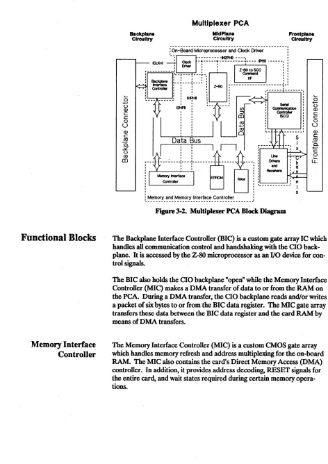
The Circuit Planes . . • . . . .. 3 - 3 Backplane Interface Circuits . . . • . 3 - 3 Midplane Circuits . . . 3 - 3 Frontplane Circuits • • • . . . • . . . .. 3 - 3 Functional Blocks . . . • • . . . 3 - 4
Memory Interface Controller . . . • • . . . • . . 3 - 4
Clock Driver . . . • . . . • . . . • . . • . . 3 - 5 Microprocessor . • • . . . • . . . • . • • .. 3 - 5 Z-SO to SCC Command Interface . . . .. 3 - 5 EPROM . . . • • . . . • . . . .. 3 - 5
RAM • . • . . • . • • • . • • . • • . . . • • • . • . . . 3-5
Serial Communications Controllers . . . .. 3 - 6
Line Drivers and Receivers . . . 3 - 6
4
Troubleshooting
Description of Self Test . • . . . 4 - 1 Results . . . 4 - 1
In Case of Failure
...0...
4 - 2Troubleshooting . . . 4 - 2
5
Component Parts
Component Parts . . . .. 5 - 1 Ordering Information . . . 5 - 2
6
Reference
Other References . . . .. 6 - 1 Glossary . . . .. 6 - 2 Safety Ground . . . .. 6 - 6 Supported Modems . . . 6 - 6 Connecting Cables (RS-232-C) . . . 6 - 7
7
Diagrams
1
Description
General Information
This manual describes the the HP 27140A Asynchronous 6-Channel Multi- . plexer (MUX) Interface. We use the terms "multiplexer", "MUX", "HP 27140A", and its full name interchangeably to describe the entire product. The terms "board", "card" and "PCA" designate the printed circuit assemb-ly as distinct from the entire product.
The HP 27140A accesses any of the computers using the Hewlett-Packard Channel Input/Output backplane standard. (Channel 110 is a Hewlett-Packard standard derming the electrical and physical characteristics for an Input/Output system.) The multiplexer supports RS-232-C and CCITT V.24 and V.28 communications standards.
The factory setting for the information transmission rate is 9600 baud. The MUX is also programmable to process rates from 50 to 19200 baud. See Chapter 2, "Installation and Configuration", for the information needed to use the six communications ports.
This multiplexer provides for Input and Output (110) through multiple modems from remote locations via telephone lines. This product has the appropriate control lines for connection to any modem which adheres to RS-232-C or CCITT V.24 and V.28. There are no modems included with
this multiplexer . The MUX also communicates with local, direct-connect
devices, and supports any mix of six peripherals while using only one card slot in the computer backplane.
Your local telephone company or your long distance carrier will be able to install conditioned telephone lines if your modems or applications require them.
Specifications
Features
Functional
Specifications
Capacity
1-2 General Information
Six full duplex asynchronous serial I/O ports with 10 wire modem control capability (satisfies European licensing requirements).
EIA RS-132-C and CCITf V.28 compatibility. Full duplex modem operation only.
Support for use as a local system console on port
o.
Programmable data rates for each channel. Programmable number of stop bits: 1, 1.5, 2. Programmable parity:. odd, even, none.Programmable character size: 5, 6, 7, or 8 data bits.
Parity, overrun, framing error check detects transmission faults. Yumware based self test helps assure card integrity.
Programmable device XON/XOFF handshaking to pace MUX output data transmission.
On-board buffering with DMA capability to send/receive data for multiple ports in a single transfer.
Channels: Six channels - full duplex.
Buffering: On card buffering with DMA capability to send/receive for multiple ports in a single transfer to reduce host CPU interrupts and increase throughput.
Transmit Buffer Size: 255 bytes per port.
Communications
Edit Functions
Interface Level:
nata Rates:
Throughput:
Modem Support:
RS-232-C and CCI'IT V.2B.
Defaults to 9600; software programmable to any of 16 transfer rates: SO, 75, 110, 134.5,150,300,600,900,1200,1800,2400, 3600, 4800, 7200, 9600, and 19,200 baud.
Supports six interactive terminal users running character mode at 19,200 baud. Other RS-232-C applications receiving and sending simultaneously should be run at 9600 baud or slower. (Refer to Table 1-1 for details on transmission rates.)
Originate mode. Auto-answer mode. Modem connection timer. Lost receiver ready timer. No-activity timer.
Host control of every card output modem line.
Communications Mode: Asynchronous, bit serial.
Break Detection: Break conditions are recognized by the card and cause interrupts to the host. The MUX can also generate break conditions as they are needed. A break is a "space" condition for two consecutive character times.
Optional Handshaking: All handshaking is optional and
programmable. The protocol characters are also programmable. Device controlled XON/XOFF is performed at the card level.
The MUX passes edit functions (i.e., backspace, character delete, etc.) to the host. They are then managed by the host operating system.
Electrical and Physical
Specifications
Direct Current
Requirements
Physical Dimensions
Environmental
Specifications
Firmware
Equipment
Supplied
1-4 General Information
Typical
+
Two aVoltage Current (Standard Deviation)
+5 1.380 A
+12 0.084 A
-12 0.125 A
Length: 17.72cm
Width: 17.70cm
1hickness: 2.95mm
Weight (card only): 270 grams
2.298 A 0.159 A 0.150 A
(7 in)
(7 in)
(0.12 in) (9.5 oz)
The MUX card is sensitive to humidity and temperature. The card
operates between 0 and SOOC and should be stored only where the
temperature will range from -40 to 7SOC. Humidity (@ 4<rC
non-condensing) should be maintained between 5% and 95%.
The PCA includes one EPROM (Erasable, Programmable, Read Only Memory) chip. The EPROM contains the on board self test and
download monitor programs. Self test is described in Chapter 4,
"Troubleshooting".; The download monitor directs the downloading of control codes for board operation and insures that they are correct and stored properly. The EPROM also provides enough on board intelligence
to use port 0 for communications with a terminal. This feature is typically
used for the system control console for the initial system boot-up.
The HP 27140A is designed for HP 9000 Series 500 computers:
Description
Multiplexer PCA RS-232-C Junction Panel Cable, PCA-to-Panel, 1 metre This Reference Manual
Part Number
27140-60001
28659-60005 28659-63002
Options and
Additional Equipment
Suggested Cables for
Use with Terminals
Suggested Cable for
Modem Installations
RS-232-C Junction
Panel
I
Note
I
The following items are also available through HP Sales and Support Of-fices if you did not order them with the system. The 10-metre extension cable connects to the standard cable for greater flexibility in installation. Use of the Test Hood is described in Chapter 4, "Troubleshooting".
27140A
Option #001: Option #019: Option #540:
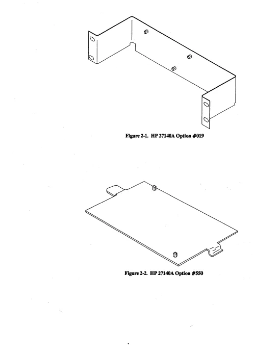
Option #550:
27140-60003
Extension cable 10 metre, pIn 28659-63004
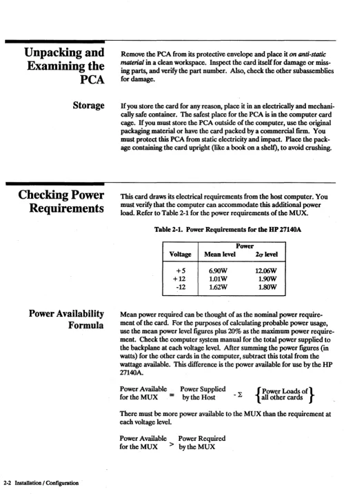
19 inch Rack Mounting Bracket Kit, pIn 5061-4962 Mounting Bracket Kit for 9040A Systems,
pIn 5061-4963
Mounting Bracket Kit for 92211R Cabinet, pIn 5001-5280
Test Hood
The following cables are designed to connect the MUX RS-232-C Junc-tion Panel to your terminals:
• HP 13242M (5 metres)
• HP 13242N (5 metres)
• HP 13242Y (5 metres)
• HP922190 (3.8 metres).
The HP 922190 cable, 5 metres long, is designed to connect the MUX to a modem.
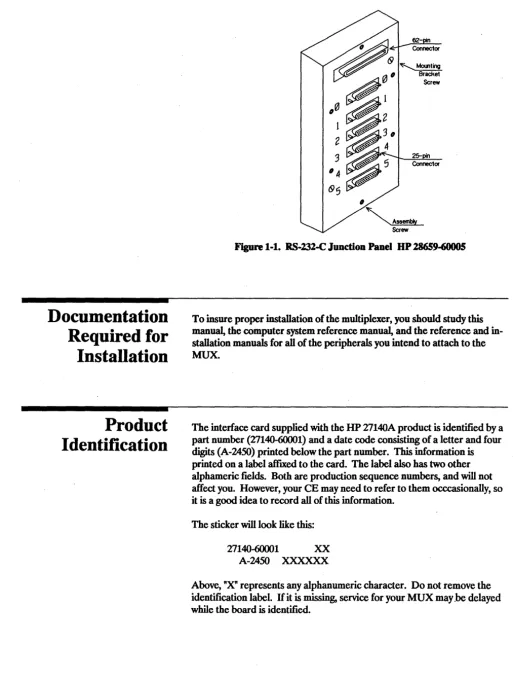
The RS-232-C Junction Panel (28659-60005) is a six-port junction box which provides serial, asynchronous interconnections between the multi-plexer card and a modem or terminal device. See Figure 1-1. This panel
has one 62-pin receptacle and six 25-pin D subminiature female connec-tors on the front.
This RS-232-C Junction Panel is considered a field replaceable unit and should be replaced on failure. Hewlett-Packard does not support user maintenance of this component. Contact your HP Sales and Support Office for additional information.
Documentation
Required for
Installation
Product
Identification
1-6 GenerallnformatioD
II
[image:14.620.43.556.78.755.2]~
ScrewFigure 1·1. RS·232-C Junction Panel HP 28659-60005
To insure proper installation of the multiplexer, you should study this manual, the computer system reference manual, and the reference and in-stallation manuals for all of the peripherals you intend to attach to the MUX.
The interface card supplied with the HP 27140A product is identified by a part number (27140-60001) and a date code consisting of a letter and four digits (A-2450) printed below the part number. This information is
printed on a label affIXed to the card. The label also has two other
alphameric fields. Both are production sequence numbers, and will not
affect you. However, your CE may need to refer to them occcasionally, so
it is a good idea to record all of this information.
The sticker will look like this:
27140-60001 XX
A-2450 XXXXXX
Above, "X" represents any alphanumeric character. Do not remove the
identification label. If it is missing, service for your MUX may.be delayed
Support Strategy
Cable Repair
User Responsibility
System Console
The HP 27140A Multiplexer Interface card is a Field Replaceable Unit (FRU). The electronic components and circuitry on the card are not repairable except under factory conditions. Exchanging boards also sig-nificantly reduces downtime compared to removing, repairing and replac-ing the original card. Whenever the PCA is replaced, remove the EPROM and retain it for insertion in the replacement card, as the new
card will not have an EPROM on it. Insure that precautions are taken to
protect the EPROM from static discharge.
Component level repair is not supported by Hewlett-Packard. Users who attempt repair at this level may invalidate their warranties. The sole ex-ception to this guideline is the EPROM. Your HP Customer Engineer
will remove it, have it tested and replace it if necessary.
The multiplexer is designed with an extremely compact cable connector. Because of the tolerances for the cable connector it is impossible to repair
or modify the board connector end of the PCA -to-Panel cable. Any
failure of the cable at the board connector end requires replacement of the cable assembly.
The junction panel end of the cable was fabricated using a conventional connector. Tables in Chapter 6, "Reference", list the pin assignments for this cable.
There are no physical adjustments to make on this card nor is any special preventive maintenance required. You may want to clean the computer
card cage occasionally. If so, your computer manual will have instructions
on this subject. In case of apparent card failure, run the self test described
in Chapter 4. If the board fails, call your HP Customer Engineer.
If the system console is attached to port 0 of the RS-232-C Junction Panel,
the resident fIrmware on this card will transmit to and receive from the
console at 9600 baud, using 8 bit ASCII characters with no parity check bit. There will be one stop bit.
Buffer Capacity
I
Note
I
1-8 General Information
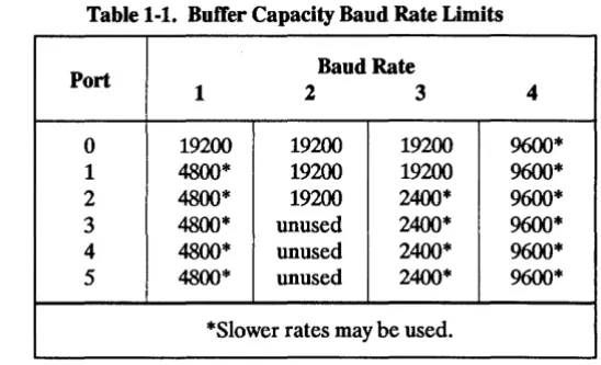
[image:16.615.238.512.218.384.2]The HP 27140A uses a 4Kbyte buffer to temporarily store data to be sent to the host computer. Because of the distinctive system used to identify each character received, this capacity provides actual character storage equal to lKbyte. Buffer space is dynamically allocated to the six ports as they require it. Thus, no one port has specific buffer address space dedi-cated to it. This buffer capacity limits the throughput of the MUX. Table 1-1 lists four possible combinations of baud rates for the HP 27140A.
Table 1-1. ButTer Capacity Baud Rate Limits
Port Baud Rate
1 2 3 4
0 19200 19200 19200 9600*
1 4800* 19200 19200 9600*
2 4800* 19200 2400* 9600*
3 4800* unused 2400* 9600*
4 4800* unused 2400* 9600*
5 4800* unused 2400* 9600*
*Slower rates may be used.
All of these speeds assume full duplex operation and near 100% utiliza-tion of channel capacity. Operautiliza-tion at higher speeds than noted may result in DATA OVERRUN errors.
When all six terminals are being used by people in interactive programs, it is unlikely that the users could overload the buffer, since human beings do not enter data rapidly enough to use the potential of 19200 baud. In this case, all six ports could be programmed to 19200.
2
I
Caution
I
Site Preparation
Installation / Configuration
Please read all of the sections of this chapter which apply to your com-puter before proceeding with the installation of your HP 27140A Multi-plexer.
Installing this PCA involves the following steps:
1. Unpacking and examining the card (temporary storage is also discussed).
2. Inserting the card into the computer card cage. 3. Testing the unit.
4. Attaching MUX-to-Junction Panel, Modem, and RS-232-C direct connect cables.
After installation, the card is configured by programmatic instructions.
Many of the components of the HP 27140A are susceptibl~ to destruction or degradation by electrostatic discharge. See the safety considerations in the front of this manaul. To handle this card, use only the edges and ex-tractor levers to avoid damage to components. /~
There is no site preparation required for this product other than proper installation of the host computer.
Using the MUX will require that several cables be attached to the RS-232-C Junction Panel. RS-232-Consideration must be given to locating the RS-232-RS-232-C Junction Panel mounting bracket so that these cables present no problems to traffic or maintenance of the computer. The RS-232-C standard limits the length of cable from the card itself to any terminal device to a total of 15 metres (SO feet).
Unpacking and
Examining the
peA
Storage
Checking Power
Requirements
Power Availability
Formula
2-2 Installation I Configuration .
Remove the PCA from its protective envelope and place it on anti-static
material in a clean workspace. Inspect the card itself for damage or miss-ing parts, and verify the part number. Also, check the other subassemblies for damage.
H you store the card for any reason, place it in an electrically and
mechani-cally safe container. The safest place for the PCA is in the computer card
cage. If you must store the peA outside of the computer, use the original
packaging material or have the card packed by a commercial firm. You must protect this PCA from static electricity and impact. Place the pack-age containing the card upright (like a book on a shelf), to avoid crushing.
[image:18.613.49.548.52.781.2]This card draws its electrical requirements from the host computer. You must verify that the computer can accommodate this additional power load. Refer to Table 2-1 for the power requirements of the MUX.
Table 2-1. Power Requirements for the UP 27140A
Power
Voltage Mean level 2alevel
+5 6.90W 12.06W
+12 1.01W 1.90W
-12 1.62W I.SOW
Mean power required can be thought of as the nominal power require-ment of the card. For the purposes of calculating probable power usage, use the mean power level figures plus 20% as the maximum power require-ment. Check the computer system manual for the total power supplied to
the backplane at each voltage level. After summing the power fIgUl'es (in
watts) for the other cards in the computer, subtract this total from the
wattage available. This difference is the power available for use by the HP
27140A.
Power Available Power Supplied
for the MUX
=
by the Host - L { all other cards Power Loads Of}There must be more power available to the MUX than the requirement at each voltage level.
Power Available Power Required
Inserting the Card
ti''''''',)
Removing the
Card
I
Note
I
If the power available is too low to meet the requirements of the MUX at each voltage level, you must augment the computer power supply, or remove another board before installing the card. Contact your HP Sales and Support Office for details.
Refer to the System Installation and Configuration Guide included with
your system for the proper placement and positioning of the card.
Before attempting to install this (or any) peA, follow the computer "shut . down" procedure and TURN OFF the computer power supply. Failure to disconnect the current could result in an electrical shock, and it may damage both the computer and the card. Any resultant damage will not be covered by warranty.
The 27140A MUX card uses friction at the backplane contacts to hold the card in place. Hold the card firmly by the extractor levers and gently push it into the track-like guides of the slot. Once the card touches the back-plane connectors (you'll notice the resistance), press it firmly into the backplane. As the card reaches its limit of travel, the free ends of the ex-tractor levers will start to fold down against the card. Press on them until the card is fully seated in the backplane.
To remove the card, grasp the free ends of the extractor levers, and pivot them toward you (away from the card cage). This will force the card out slightly from the connectors at the backplane. Continue pulling, but be careful to pull both levers evenly to avoid jamming the PCA or breaking its components. Use the same caution against static build-up and dis-charge discussed in the paragraph on unpacking the card while handling the board once you have removed it.
Repair or replacement of other electronic components could invalidate your warranty.
Testing the Unit
Attaching the
Cables
MUX-to-Junction
Panel Cable
24 Installation I Configuration
Once you have correctly installed the PCA you should test it to verify proper operation of the MUX. While self test may be run with or without the connecting cable attached to the board, you should initially run the test before attaching it. Self test is executed automatically on power up. The information you need to interpret the results of self test are found in Chapte .. 4. Basically, if the LED on the card stays off after 45 seconds, the card is working correctly.
The cables you will use are the MUX-to-Junction Panel cable and the RS-232-C cables attached to your peripheral devices. Before attaching the peripheral cables to the junction pane~ check the manuals for any specific cabling requirements.
The MUX-to-Junction cable is a 62-conductor cable with a proprietary female connection which fits the card edge connector. This fitting is black plastic with a metal ground striponthe back. The RFI grounding clip (grommet) approxinlately two inches (5 em) from the connection will help you identify it. Press this connection fumly onto the PCA mounted con-nector with the cable exiting the concon-nector on the bottom. Press the grom-met fumly into the slot on the cable grounding bus below the card cage. If
Figure 2-1. HP 27140A Option #019
Figure 2-2. HP 27140A Option #SSO
RS-232-C Cables
Configuration
[image:22.617.53.531.50.755.2]2-6 Installation I Configuration
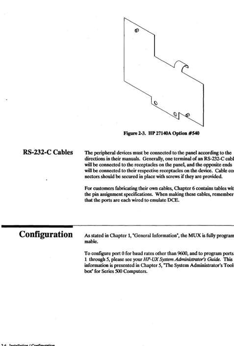
Figure 2-3. HP 27140A Option #540
The peripheral devices must be connected to the panel according to the
directions in their manuals. Generally, one terminal of an RS-232-C cable will be connected to the receptacles on the panel, and the opposite ends will be connected to their respective receptacles on the device. Cable
con-nectors should be secured in place with screws if they are provided.
For customers fabricating their own cables, Chapter 6 contains tables with the pin assignment specifications. When making these cables, remember that the ports are each wired to emulate DCE.
As stated in Chapter 1, "General Information", the MUX is fully program-mable.
To configure port 0 for baud rates other than 9600, and to program ports
1 through 5, please see your HP-UX System Administrator's Guide. This
information is presented in Chapter 5, "The System Administrator's
3
Main
Sub-assemblies
Printed Circuit
Assembly
Multiplexer-to-Panel
Cables
Functional Description
The HP 27140A Asynchronous 6-Channel Multiplexer with Modem Control is, in most cases, the primary RS-232-C interface for your com-puter. Your control of this MUX may be through a high level language, such as C or FORTRAN, a "turn-key" application program, or some other
type of program which uses the computer operating system to control the
interface. Since the user contact with the MUX is at such a high leve~ the
functional description below dermes the interface organization in terms of a few large functional blocks. This manual does not contain a component level description of the operation of the interface.
Three major sub-assemblies constitute the 27140A: the Multiplexer PCA,
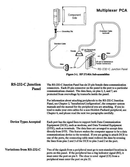
[image:23.612.59.561.52.755.2]the 6-port RS-232-C J unction Pane~ and the Multiplexer-to-Panel cables.
Figure 3-1 shows these sub-assemblies. See "Equipment Supplied" in Chapter 1 for sub-assembly part numbers.
A Channel Input/Output (CIO) PCA fits into a CIO backplane, gets its power from the backplane, and receives data from the host computer and peripheral devices. The multiplexer PCAconverts signals and data from the CIO backplane protocol to the RS-232-C protocol used by
peripherals. Conversely, the MUX also converts data from up to six RS-232-C peripherals to the CIO protocol.
These cables are used to carry signals to and from the RS-232-C Junction Panel in a single, manageable package. The cable contains six sets of wire. Each set is dedicated to one of the communication channels. The braided shield just under the cable outer jacket connects the safety ground on the card to the safety ground on the panel.
Depending on how your computer is installed, the standard MUX-to-Panel cable may go to a RS-232-C Junction MUX-to-Panel that is on the inside or the outside of the computer main cabinet. The cable 62-pin male
connec-tor plugs into the large RS-232-C Junction Panel receptacle. If the panel
must be located farther from the computer, an extension cable is available as an option.
RS-232-C Junction
Panel
Device Types Accepted
Variations from RS-232-C
3-2 Functional Description
Standard Cable
/
Component Side
Multiplexer
peA
\
ExtenSion Cable [image:24.615.45.542.64.701.2]<optionaD
Figure 3-1. UP 27140A Sub-assemblies
The RS-232-C Junction Panel has six 25-pin female data-communication connectors. Each 25-pin connector on the panel is the port to a particular
communications channel. The data lines, on pins 2, 3, and 7, are
protected from overvoltage by transorbs inside the panel.
For information about attaching peripherals to the RS-232-C Junction
Pane~ see Chapter 2, "Installatiori/Configuration", the computer system
manuals and the manual for the peripheral you are attaching. If you
in-tend to make your own cables for a non-Hewlett-Packard peripheral, see Chapter 6, and please read the next two paragraphs carefully.
Each port has the signal lines to support both Data Communication Equipment (DCE), such as modems, and Data Terminal Equipment (DTE), such as terminals. The data lines are arranged to accept data directly from DTE. This feature makes the computer appear to be a data
communications device to the terminal. If you are going to attach DCE to
one of the ports, the connecting cable must redirect the data by crossing the lines from pins 2 and 3 of the DCE to pins 3 and 2 at the port.
Two of the signals from a peripheral must go to non-standard locations in
ports on this panel. If the peripheral has a ring indicator signal (RI), it
Organization
The Circuit Planes
Backplane Interface
Circuits
Midplane Circuits
Frontplane Circuits
To understand how the MUX card circuitry is organized, it is convenient
to think of the card as being divided into three planes of circuits. While each plane would theoretically perform specific tasks, the planes actually work in concert to accomplish some operations. The three major circuits are:
• Backplane interface circuits
• Midplane circuits
[image:25.618.48.567.82.785.2]• Frontplane interface circuits
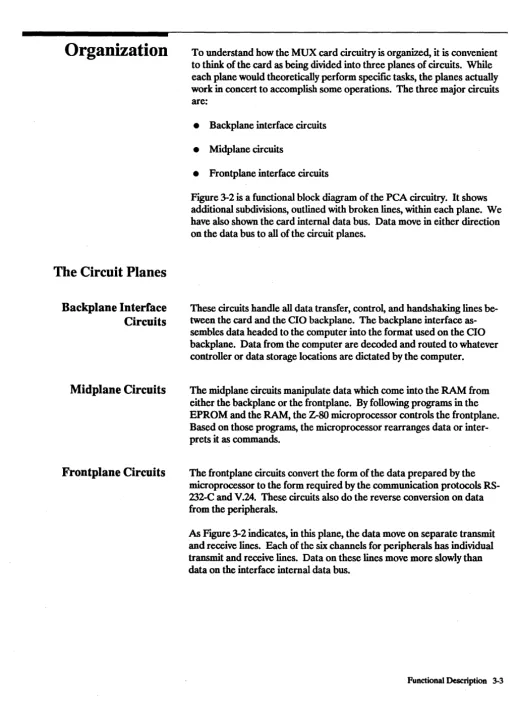
Figure 3-2 is a functional block diagram of the PCA circuitry. It shows
additional subdivisions, outlined with broken lines, within each plane. We have also shown the card internal data bus. Data move in either direction on the data bus to all of the circuit planes.
These circuits handle all data transfer, control, and handshaking lines be-tween the card and the CIO backplane. The backplane interface as-sembles data headed to the computer into the format used on the CIO backplane. Data from the computer are decoded and routed to whatever controller or data storage locations are dictated by the computer.
The midplane circuits manipulate data which come into the RAM from either the backplane or the frontplane. By following programs in the EPROM and the RAM, the Z-SO microprocessor controls the frontplane. Based on those programs, the microprocessor rearranges data or inter-prets it as commands.
The frontplane circuits convert the form of the data prepared by the microprocessor to the form required by the communication protocols RS-232-C and V.24. These circuits also do the reverse conversion on data from the peripherals.
As Figure 3-2 indicates, in this plane, the data move on separate transmit and receive lines. Each of the six channels for peripherals has individual transmit and receive lines. Data on these lines move more slowly than
data on the interface internal data bus.
Functional Blocks
Memory Interface
Controller
3-4 Functional Description
<5
+-' U (l) c: c: o U (l) c: ro 0. .::s:. u ro CO Backplane CircuitryMultiplexer peA
MidPlane
Circuitry Frontplane Circuitry
: On-Board Microprocessor and Clock Driver
-,
IClK+) 'Clock : ; : : : : : ; :~~:: :::- - - - FHI . - ----,
: Driver
:---l-~---~-• I . I I I
: Backplane : __ ~---J---! :
Interface " ' ,
, Contreller : : : :
I • I I • I I I • ,
!.. _________ , : Hf!HI :
0iPl:
'
Data Bus
, , , , , , , , , , ,
r---,-:
r---'---(/) ~ CO ro +-' ro o SerIal CornnuIicatlal Controller ISCO s
I ::
I 11
r---~----l----l---~-
--- ----: l
andO--L--_----O'_....,' : : Receivers
Memory Interface EPROM : : .... ,... n ,
RAM "
Contreller : : ___________
J
e, I
[image:26.612.62.534.58.726.2], s
Figure 3-2. Multiplexer PeA Block Diagram
<5
+-' U (l) c: c: o U (l) c: ro 0.. +-' c: ou::
The Backplane Interface Controller (BIC) is a custom gate array IC which handles all communication control and handshaking with the CIO back-plane. It is accessed by the Z-SO microprocessor as an I/O device for con-trol signals.
The BIC also holds the CIO backplane "open" while the Memory Interface Controller (MIC) makes a DMA transfer of data to or from the RAM on the PCA. Duririg a DMA transfer, the. CIO backplane reads and/or writes a packet of six bytes to or from the BIC data register. The MIC gate array transfers these data between the BIC data register and the card RAM by means of DMA transfers.
The Memory Interface Controller (MIC) is a custom CMOS gate array which handles memory refresh and address multiplexing for the on-board RAM. The MIC also contains the card's Direct Memory Access (DMA) . controller. In addition, it provides address decoding, RESET signals for
Clock Driver
Microprocessor
Z-80 to SCC Command
Interface
EPROM
RAM
The HP 27140A uses the 14.7456 MHz clock signal from the host com-puter (CLK
+ )
as a basis for each of the four on-board clock signals. These four synchronized clock signals are:• 3.6864 MHz (PHI) -- system clock for Z-SOB CPU, SCCs, the back-plane and the MIC
• 737'18 MHz (2PHI) -- drives the MIC
• 7.37'18 MHz (N2PHI) -- (inverted 2PHI) drives the Z-SO to SSC Com-mand Interface
• 1.8432 MHz (HPHI) -- drives the Request Hold Off (wait state) clock oftheMIC
The Z-SOB microprocessor commands the circuits that control the frontplane and organizes data for transmission to the computer or peripherals. The Z-SO reads its instructions on how to carry out its tasks from the EPROM or the RAM. The EPROM permanently stores the programs the Z-SO will need to get the card started.
With the programs in the EPROM, the Z-SO can control port 0 and check programs loaded into the RAM. In some computer systems, port 0 is where the system control console will be attached. The Z-SO is able to control ports 1 to 5 only after the computer loads an additional frontplane control program into the RAM. This additional program comes with your computer operating system. The microprocessor also arranges data in the RAM for DMA transfers. This saves the computer processsor time.
This interface is a PAL, Programmable Array Logic. The PAL has been programmed to allow signals on the microprocessor co~trollines to con-trol the Serial Communication Concon-trollers and associated circuits on the frontplane.
The EPROM is the permanent memory for the MUX. The self test, DMA monitor, and primary port 0 control programs are stored on the EPROM.
The RAM is a volatile memory where data and programs can be stored. The Z-SO and MIC can take exclusive control of the RAM for some data manipulations.
Serial Communications
Controllers
Line Drivers and Receivers
3-6 Functional Description
The Serial Communication Controllers (SCC) do the data format conver-sions for data going to or coming from peripherals. The
sces
also monitor most of the modem control lines. A Counter-Timer Parallel 110 controller associated with thesces
controls the SR and DM modem con-trol signals of the RS-132 ports. The Z-SO concon-trols and monitors the SCC via the Z-SO to SCC command interface.4
Description of
Self Test
Results
,*"",,,(.)
Troubleshooting
The MUX has an on-board self test to verify operation of the card. This
chapter explains how to initiate self test and how to interpret the results.
The HP 27140A card has a self-test program stored in the EPROM chip mounted on the board. The program executes each time the card is RESET, or on command from the operator. The test operates on a GOINO-GO basis and determines whether the card will reliably pass data in both directions.
There are, in fact, two self tests. The fIrSt, without the optional test hood, verifies the on-board circuitry of the EPROM itself, the RAM, operation of the Z-SO microprocessor, and resident DMA and timer chip operation. The test hood allows further testing of the Z-SO Serial Communications Controller (SCC) circuits, the line drivers and receivers. (See "Options and Additional Equipment" in Chapter 1 for test hood part number.)
The normal method of receiving the results of the self test is through the system console. In some cases, however, this may be impossible due to hardware or software failure in the system console circuit.
Never attempt to defeat an interlock system. It is there to protect you from shock and the computer from damage. (Please note that HP engineers have special tools which allow them to by-pass an interlock safely.)
In Case of Failure
Troubleshooting
4-2 Troubleshooting
If the I/O channel fails, and does not allow the results to be read from the host, an LED mounted on the board may be used to interpret the test results. If the optional test hood is in place, a second LED mounted on the hood itself also shows whether the tests were successful. Using the test hood does not change the length of time that the self test takes to run. The LED mounted on the board (and the one on the hood) will light up for approximately 2 seconds, go out and blink again if the test was ex-ecuted due to a RESET (or power on) condition. This sequence will repeat up to five times while the computer verifies backplane operations. A second method for initiating self test is through the DEVICE CLEAR! DEVICE ENABLE sequence, which will light the LED(s) for 13 to 15 seconds. In either case, if the LED fails to go out, self test has failed.
In the event the board fails the EPROM-controlled self test, repeat the operation (RESET or DEVICE CLEAR/DEVICE ENABLE) using the on board LED(s) to verify the failure. You should call your HP Customer Engineer and give him the results of the self test. This will enable him to resolve any problem more quickly.
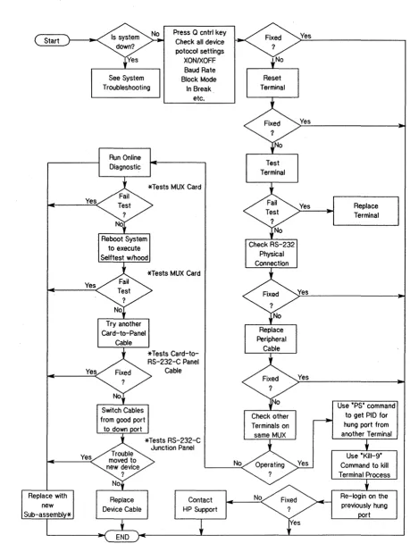
Since the MUX is the hub of a network of devices, including the host com-puter, it may appear to malfunction when another device has actually failed. When you are faced with such a failure, the troubleshooting tree in FIgUre 4-1 will help isolate the problem.
When checking the device protocol settings, you should also check the sys-tem control panel for error status messages.
When we ask you to test the terminal, remember that all Hewlett-Packard terminals have a self-test function built in. For terminals built by other manufacturers, you will have to refer to their literature to determine how to test the terminal.
When checking the RS-232-C physical connection, you should check the cable connector on the card and at the RS-232-C Junction Panel, and each peripheral cable as it leaves the junction panel. You should also check the connection at the peripheral connector. Check the continuity of the cables; rats and mice like to chew on them.
The asterisks "*" in the diagram tie the phrase "*Tests xxx" to the cell "Replace with new Sub-assembly*". You should permanently replace the sub-assembly being tested at the branch which directed you to this cell. Switching the cables between two peripherals at the panel will help deter-mine if the trouble is in the RS-232-C Junction Panel. If the trouble moves to the new port terminal, then the problem was on the computer-to-junc-tion panel side of the circuit. At this point, having eliminated the others, the junction panel is the only remaining suspect component.
If you must contact HP resources, please begin with you HP Sales and Support Office. (A list of these offices is included at the end of this
manual.) If the solution is beyond their capabilities, the Sales and Support Office will contact the appropriate HP entities to get the problem solved.
Yes
Yes
4-4 Troubleshooting
See System Troubleshooting
Run Online Diagnostic
Press Q cntrl key Check all device potocol settings
XON/XOFF Baud Rate Block Mode In Break.
etc.
*Tests MUX Card
*Tests MUX Card
Reset Terminal
Test Terminal
[image:32.613.57.516.67.685.2]Yes
Figure 4-1. Troubleshooting Tree for the UP 27140A
5
I
Note
I
Component Parts
Component Parts
Only the MUX card, the cable(s), the RS-232-C Junction Panel, and the EPROM are treated by Hewlett-Packard Company as Replaceable Parts. Users who attempt component level repair or replacement may invalidate their warranties.
[image:33.615.55.557.67.742.2]This chapter contains information for ordering component parts for the HP 27140A PCA. Figure 7-4 shows the locations of the PCA components. Table 5-1 is the listing of all component parts for the MUX in reference designation order. The following information is provided in the table. 1. Reference designation of the part.
2. The Hewlett-Packard part number. 3. Part number check digit (CD). 4. Total quantity (OTY).
5. Description of the part.
6. A five-digit manufacturer's code number of a typical manufacturer of the part. Refer to Table 5-2 for a cross reference of the manufacturers.
7. The manufacturer's part number.
Ordering
Information
5-2 Component Parts
To order component parts or to obtain information on parts, address the order or inquiry to the nearest Hewlett-Packard Sales and Support Office listed at the back of this manual.
To order a part listed in the component parts table, quote the Hewlett-Packard part number (with the check digit) and indicate the quantity required. The check digit will insure accurate and timely processing of your order.
To order a part that is not listed in the table, specify the following infor-mation:
1. Identification of the product containing the part. 2. Description and function of the part.
Table 5-1. HP 27140A Component Parts
Reference HPPart C Qty Description Mfr Mfr Part Number
Designation Number D Code
27140-60001 8 1 PCA-6CH MOD MUX 28480 27140-60001
C1 0160-4835 7 6 CAPACITOR-FXD .1UF +-10% 50VDC CER 28480 0160-4835
C2 0160-6500 7 15 CAPACITOR-FXD .0IUF +-10% 100VDC CER 02802 CAC02X7RI03K100C
C3 0160.,.4810 8 54 CAPACITOR-FXD 330PF +-5% 100VDC CER 28480 0160-4810
C4 0160-4810 8 CAPACITOR-FXD 330PF +-5% 100VDC CER 28480 0160-4810
C5 0160-4835 7 CAPACITOR-FXD .IUF +-10% 50VDC CER 28480 0160-4835
C6 0160-4810 8 CAPACITOR-FXD 330PF +-5% 100VDC CER 28480 0160-4810
C7 0160-4810 8 CAPACITOR-FXD 330PF +-5% 100VDC CER 28480 0160-4810
C8 0160-4810 8 CAPACITOR-FXD 330PF +-5% 100VDC CER 28480 0160-4810
C9 0160-4810 8 CAPACITOR-FXD 330PF +-5% 100VDC CER 28480 0160-4810
CI0 0180-1746 5 2 CAPACITOR-FXD 15UF+-I0% 20VDC TA 56289 150D156X9020B2
C11 0160-6500 7 CAPACITOR-FXD .01UF +-10% 100VDC CER 02802 CAC02X7R103K100C
C12 0160-6500 7 CAPACITOR-FXD .0IUF +-10% 100VDC CER 02802 CAC02X7RI03KI00C
C13 0160-4810 8 CAPACITOR-FXD 330PF +-5% 100VDC CER 28480 0160-4810
C14 0160-4810 8 CAPACITOR-FXD 330PF +-5% 100VDC CER 28480 0160-4810
C15 0160-4810 8 CAPACITOR-FXD 330PF +-5% 100VDC CER 28480 0160-4810
C16 0160-4810 8 CAPACITOR-FXD 330PF +-5% 100VDC CER 28480 0160-4810
C17 0160-4810 8 CAPACITOR-FXD 330PF +-5% 100VDC CER 28480 0160-4810
C18 0160-4810 8 CAPACITOR-FXD 330PF +-5% 100VDC CER 28480 0160-4810
C19 0160-4810 8 CAPACITOR-FXD 330PF +-5% 100VDC CER 28480 0160-4810
C20 0160-4810 8 CAPACITOR-FXD 330PF +-5% 100VDC CER 28480 0160-4810
C21 0160-6500 7 CAPACITOR-FXD .01UF +-10% 100VDC CER 02802 CAC02X7RI03K100C
C22 0160-4810 8 CAPACITOR-FXD 330PF +-5% 100VDC CER 28480 0160-4810
C23 0160-4810 8 CAPACITOR-FXD 330PF +-5% 100VDC CER 28480 0160-4810
C24 0160-4810 8 CAPACITOR-FXD 330PF +-5% 100VDC CER 28480 0160-4810
C25 0160-4810 8 CAPACITOR-FXD 330PF +-5% 100VDC CER 28480 0160-4810
C26 0160-4810 8 CAPACITOR-FXD 330PF +-5% 100VDC CER 28480 0160-4810
C27 0160-4810 8 CAPACITOR-FXD 330PF +-5% 100VDC CER 28480 0160-4810
C28 0160-4810 8 CAPACITOR-FXD 330PF +-5% 100VDC CER 28480 0160-4810
C29 0160-4810 8 CAPACITOR-FXD 330PF +-5% 100VDC CER 28480 0160-4810
C30 0160-6500 7 CAPACITOR-FXD .0IUF +-10% 100VDC CER 02802 CAC02X7RI03KI00C
C31 0160-4835 7 CAPACITOR-FXD .IUF +-10% 50VDC CER 28480 0160-4835
C32 0160-6500 7 CAPACITOR-FXD .0IUF +-10% 100VDC CER 02802 CAC02X7R103K100C
C33 0160-4810 8 CAPACITOR-FXD 330PF +-5% 100VDC CER 28480 0160-4810
C34 0160-4810 8 CAPACITOR-FXD 330PF +-5% 100VDC CER 28480 0160-4810
C35 0160-4810 8 CAPAC I TOR-FXD 330PF +-5% 100VDC CER 28480 0160-4810
C36 0160-4810 8 CAPACITOR-FXD 330PF +-5% 100VDC CER 28480 0160-4810
C37 0160-4810 8 CAPACITOR-FXD 330PF +-5% 100VDC CER 28480 0160-4810
C38 0160-4810 8 CAPACITOR-FXD 330PF +-5% 100VDC CER 28480 0160-4810
C39 0160-4810 8 CAPACITOR-FXD 330PF +-5% 100VDC CER 28480 0160-4810
C40 0160-4810 8 CAPACITOR-FXD 330PF +-5% 100VDC CER 28480 0160-4810
C41 0160-6500 7 CAPACITOR-FXD .0IUF +-10% 100VDC CER 02802 CAC02X7RI03KI00C
C42 0160-6500 7 CAPACITOR-FXD .01UF +-10% 100VDC CER 02802 CAC02X7R103K100C
C43 0160-4810 8 CAPACITOR-FXD 330PF +-5% 100VDCCER 28480 0160-4810
C44 0160-4810 8 CAPACITOR-FXD 330PF +-5% 100VDC CER 28480 0160-4810
C45 0160-4810 8 CAPACITOR-FXD 330PF +-5% 100VDC CER 28480 0160-4810
C46 0180-1746 5 CAPACITOR-FXD 15UF+-I0% 20VDC TA 56289 150D156X9020B2
C47 0160-4810 8 CAPACITOR-FXD 330PF +-5% 100VDC CER 28480 0160-4810
C48 0160-4810 8 CAPACITOR-FXD 330PF +-5% 100VDC CER 28480 0160-4810
C49 0160-4810 8 CAPACITOR-FXD 330PF +-5% 100VDC CER 28480 0160-4810
C50 0160-4810 8 CAPACITOR-FXD 330PF +-5% 100VDC CER 28480 0160-4810
Table S~l. UP 27140A Component Parts (continued)
Reference UP Part C Qty Description Mfr Mfr Part Number
Designation Number D Code
C51 0160-4810 8 CAPACITOR-FXD 330PF +-5% 100VDC CER 28480 0160-4810
C52 0160-4810 8 CAPACITOR-FXD 330PF +-5% 100VDC CER 28480 0160-4810
C53 0160-4810 8 CAPACITOR-FXD 330PF +-5% 100VDC CER 28480 0160-4810
C54 0160-4810 8 CAPACITOR-FXD 330PF +-5% 100VDC CER 28480 0160-4810
C55 0160-4810 8 CAPACITOR-FXD 330PF +-5% 100VDC CER 28480 0160-4810
C56 0160-4810 8 CAPACITOR-FXD 330PF +-5% 100VDC CER 28480 0160-4810
C57 0180-0228 6 1 CAPACITOR-FXD 22UF+-I0% 15VDC TA 56289 150D226X9015B2
C58 0160-6500 7 CAPACITOR-FXD .0IUF +-10% 100VDC CER 02802 CAC02X7R103KI00C
C59 0160-4835 7 CAPACITOR-FXD .1UF +-10~ 50VDC CER 28480 0160-4835
C60 0160-4835 7 CAPACITOR-FXD .1UF +-10% 50VDC CER 28480 0160-4835
C61 0160-4835 7 CAPACITOR-FXD .lUF+-10% 50VDC CER 28480 0160-4835
C62 0160-6500 7 CAPACITOR-FXD .01UF +-10~ 100VDC CER 02802 CAC02X7R103K100C
C63 0160-6500 7 CAPACITOR-FXD .01UF +-10% 100VDC CER 02802 CAC02X7R103KI00C
C64 0160-4810 8 CAPACITOR-FXD 330PF +-5% 100VDC CER 28480 0160-4810
C65 0160-4810 8 CAPACITOR-FXD 330PF +-5% 100VDC CER 28480 0160-4810
C66 0160-4810 8 CAPACITOR-FXD 330PF +-5% 100VDC CER 28480 0160-4810
C67 0160-4810 8 CAPACITOR-FXD 330PF +-5% 100VDC CER 28480 0160-4810
C68 0160-4810 8 CAPACITOR-FXD 330PF +-5% 100VDC CER 28480 0160-4810
C69 0160-4810 8 CAPACITOR-FXD 330PF +-5% 100VDC CER 28480 0160-4810
C70 0160-4807 3 2 CAPACITOR-FXD 33PF +-5% 100VDC CER 0+-30 28480 0160-4807
C71 0160-4807 3 CAPACITOR-FXD 33PF +-5% 100VDC CER 0+-30 28480 0160-4807
C72 0160-6500 7 CAPACITOR-FXD .01UF +-10% 100VDC CER 02802 CAC02X7RI03K100C
C73 0160-6500 7 CAPACITOR-FXD .0IUF +-10% 100VDC CER 02802 CAC02X7R103KI00C
C74 0160-6500 7 CAPACITOR-FXD .0IUF +-10% 100VDC CER 02802 CAC02X7RI03KI00C
C75 0160-6500 7 CAPACITOR-FXD .01UF +-10% 100VDC CER 02802 CAC02X7R103K100C
C76 0160-4810 8 CAPACITOR-FXD 330PF +-5% 100VDC CER 28480 0160-4810
C77 0160-4810 8 CAPACITOR-FXD 330PF +-5% 100VDC CER 28480 0160-4810
C78 0160-4810 8 CAPACITOR-FXD 330PF +-5% 100VDC CER 28480 0160-4810
C79 0160-4810 8 CAPACITOR-FXD 330PF +-5% 100VDC CER 28480 0160-4810
C80 0160-4810 8 CAPACITOR-FXD 330PF +-5% 100VDC CER 28480 0160-4810
CR1 1901-0620 3 2 DIODE-SWITCHING 60V 400MA 00-35 9NI71 IN4607
CR2 1901-0620 3 DIODE-SWITCHING 60V 400MA DO-35 9N171 1N4607
CR3 1901-0518 8 2 DIODE-SM SIG SCHOTTKY 28480 1901-0518
CR4 1901-0518 8 DIODE-SM SIG SCHOTTKY 28480 1901-0518
CR5 1990-0968 9 1 LED-LAMP LUM-INT=1.5MCD IF=15MA-MAX 28480 HLMP-5060
EXL2 0403-0547 6 1 EXTR-PC BD ORN NYL 1.6-MM-BD-THKNS 52111 50831-42-HS(MUX/6)
EXL2 1480-0116 8 2 PIN-GRV .062-IN-DIA .25-IN-LG STL 28480 1480-0116
EXRl 0403-0527 2 1 CIO EXT HNDL BLK 28480 0403-0527
EXR1 1480-0116 8 PIN-GRV .062-IN-DIA .25-IN-LG STL 28480 1480-0116
J1 1251-7276 0 1 CONN-POST TYPE .100-PIN-SPCG 80-CONT 28480 1251-7276
J2 1251-8205 7 1 CONN-POST TYPE .100-PIN-SPCG 72-CONT 28480 1251-8205
J2 1252-1742 5 1 CONN-POST TYPE .100-PIN-SPCG 72-CONT 22526 78228-003
Rl 0698-0082 7 4 RESISTOR 464 1% .125W F TC=0+-100 24546 CT4-1/8-TO-4640-F
R2 0757-0346 2 2 RESISTOR 10 1% .125W F TC=0+-100 28480 0757-0346
R3 0698-0082 7 RESISTOR 464 1% .125W F TC=0+-100 24546 CT4-1/8-TO-4640-F
R4 0698-0082 7 RESISTOR 464 1% .125W F TC=0+-100 24546 CT4-1/8-TO-4640-F
R5 0698-0082 7 RESISTOR 464 1% .12SW F TC=0+-100 24546 CT4-1/8-TO-4640-F
R6 0757-0405 4 1 RESISTOR 162 1% .125W F TC=O+-lOO 24546 CT4-1/8-TO-162R-F
R7 0757-0346 2 RESISTOR 10 1% .12SW F TC=0+-100 28480 0757-0346
R8 0811-3716 2 2 RESISTOR ZERO OHM 28480 0811-3716
R9 0811-3716 2 RESISTOR ZERO OHM 28480 0811-3716
[image:36.615.56.555.86.716.2]Table 5-1. UP 27140A Component Parts (continued)
Reference HPPart C Qty Description Mfr Mfr Part Number
Designation Number D Code
Ul1 1820-2862 7 2 IC RCVR TTL S BUS OCTL 27014 DS3667N
U13 1820-2862 7 IC RCVR TTL S BUS OCTL 27014 DS3667N
U14 1820-1633 8 3 IC BFR TTL S INV OCTL 1-INP 01295 SN74S240N
U15 1820-1633 8 IC BFR TTL S INV OCTL 1-INP 01295 SN74S240N
U17 27140-81003 4 1 PROG. 1820-3359 28480 27140-81003
U23 1820-1633 8 IC BFR TTL S INV OCTL 1-INP 01295 SN74S240N
U24 1820-0683 6 1 IC INV TTL S HEX 1-INP 01295 SN74S04N
U27 1820-2692 1 1 IC GATE TTL F EXCL-OR QUAD 2-INP 07263 74F86PC
U28 1820-1804 5 1 TRANSISTOR ARRAY 14-PIN PLSTC TO -116 04713 MPQ6842
U33 27140-81002 3 1 PROG. 1820-3358 28480 27140-81002
U34 1810-0122 7 2 NETWORK-RES 14-DIP 3.3K OHM X 13 73138 899-1-R3.3K
U36 27140-81001 2 1 PROG. 1818-3447 28480 27140-81001
XU36 1200-0567 1 1 SOCKET-IC 28-CONT DIP DIP-SLDR 28480 1200-0567
U38 1818-3059 1 8 IC NMOS 65536(64K) DYN RAM 150-NS 3-S 28480 1818-3059
U42 1820-2975 3 1 IC GATE-ARY CMOS S0166 C-2000
U43 1820-1144 6 1 IC GATE TTL LS NOR QUAD 2-INP 01295 SN74LS02N
U48 1818-3059 1 IC NMOS 65536(64K) DYN RAM 150-NS 3-S 28480 1818-3059
U52 1820-0684 7 1 IC INV TTL S HEX 1-INP 01295 SN74S05N
U55 1820-2649 8 1 IC- Z80B-CPU 28480 1820-2649
U57 1820-3267 8 1 IC GATE-ARY CMOS S0166 C2000 MASKED
U58 1818-3059 1 IC NMOS 65536(64K) DYN RAM 150-NS 3-S 28480 1818-3059
U68 1818-3059 1 IC NMOS 65536(64K) DYN RAM 150-NS 3-S 28480· 1818-3059
U73 1820-3331 7 3 IC-SERIAL COMMUNICATIONS CONTROLLER 07653 Z8530PS
U75 1820-3825 4 1 IC-COUNTER TIMER, PARALLEL I/O 28480 1820-3825
U78 1818-3059 1 IC NMOS 65536(64K) DYN RAM 150-NS 3-S 28480 1818-3059
U83 1820-3331 7 IC-SERIAL COMMUNICATIONS CONTROLLER 07653 Z8530PS
U85 1820-3331 7 IC-SERIAL COMMUNICATIONS CONTROLLER 07653 Z8530PS
U87 1810-0122 7 NETWORK-RES 14-DIP 3.3K OHM X 13 73138 899-1-R3.3K
U88 1818-3059 1 IC NMOS 65536(64K) DYN RAM 150-NS 3-S 28480 1818-3059
U91 1820-3321 8 8 IC RCVR DTL NAND LINE QUAD 04713 MC1489AL
U92 1820-3321 8 IC RCVR DTL NAND LINE QUAD 04713 MC1489AL
U93 1820-3321 8 IC RCVR DTL NAND LINE QUAD 04713 MC1489AL
U94 1820-3321 8 IC RCVR DTL NAND LINE QUAD 04713 MC1489AL
U95 1810-0485 5 1 NETWORK-RES 14-DIP22.0K OHM X 7 28480 1810-0485
U97 1820-3467 0 1 IC DRVR TTL ALS OR HEX 2-INP 01295 SN74ALS832N
U98 1818-3059 1 IC NMOS 65536(64K) DYN RAM 150-NS 3-S 28480 1818-3059
U105 1820-3321 8 IC RCVR DTL NAND LINE QUAD 04713 MC1489AL
U107 1820-3321 8 IC RCVR DTL NAND LINE QUAD 04713 MC1489AL
U108 1818-3059 1 IC NMOS 65536(64K) DYN RAM 150-NS 3-S 28480 1818-3059
U201 1820-3322 5 6 IC DRVR DTL COMM EIA RS-232C QUAD 04713 MC1488L
U202 1820-3322 5 IC DRVR DTL COMM EIA RS-232C QUAD 04713 MC1488L
U203 1820-3322 5 IC DRVR DTL COMM EIA RS-232C QUAD 04713 MC1488L
U204 1820-3322 5 IC DRVR DTL COMM EIA RS-232C QUAD 04713 MC1488L
U205 1820-3322 5 IC DRVR DTL COMM EIA RS-232C QUAD 04713 MC1488L
U206 1820-3322 5 IC DRVR DTL COMM EIA RS-232C QUAD 04713 MC1488L
U207 1820-3321 8 IC RCVR DTL NAND LINE QUAD 04713 MC1489AL
U208 1820-3321 8 IC RCVR DTL NAND LINE QUAD 04713 MC1489AL
9320-5509 3 2 LBL-LNE-PTR; .937-IN-WD X .312-IN-LG 80509 TABX 1505 MW4 P5
27140-60003 9 1 PCA TEST HOOD 28480 27140-60003
27140-80001 0 1 PC BOARD 28480 27140-80001
Table 5-2. Code List oC ManuCacturers
Code ManuCacturer Location
S0166 Fuji Kohki Ltdc Co Japan
01295 Texas Instrument Inc, Semicond Compnt Div Dallas, Texas 75222
02802 American Safety Razor Co, Div Philip Staunton, Virginia 24401
04713 Motorola Inc, Semi-cond Prod Phoenix, Arizona 85008
07263 Fairchild Corp Mountain View, California 94042
07653 Fidelity Chemical Products Co Newark, New Jersey 07114
22525 Dupont Connector Systems Camp HilI, Pennsylvania 17011
24546 Corning Electronics Santa Clara, California 95050
27014 National Semiconductor Corp Santa Clara, California 95052
28480 Hewlett-Packard Co, Corporate Hq Palo Alto, California 94304
52111 Airco Welding Products Union, New Jersey 07083
56289 Sprague Electric Co North Adams, Massachusetts 01247·
73138 Beckman Industrial Corp Fullerton, California 92632
80509 Avery Label Co Monrovia, California 91016
9N171 Unitrode Corp Lexington, Massachusetts 02173
6
Other References
Reference
This chapter contains a list of other technical manuals and related
docu-ments which will be of assistance to you. A Glossary is provided to clarify technical terms used throughout this manual.
Below is a list of reference books and manuals which will provide per-tinent information beyond the scope of this manual.
• Carr, Joseph J.,
Z80 Users Manual.
Reston, Virginia: Reston Publish-ing Company,. 1980.• CCITT Recommendation V.24, 1972
• CCITI Recommendation V.28, 1972
• EIA Standard RS-232-C, August 1969
• McGilton, Henry and Morgan, Rache~
Introducing the Unix© System.
New York: McGraw-Hill Book Company, 1983.
• McNamara, John E.,
Technical Aspects of Data Communication,
second edition. Bedford, Massachussetts: Digital Press, 1982
• Zaks, Rodnay,
Programming the Z80,
third revised edition. Berkeley: Sybex, 1982.Glossary
Baud
ccrrr
Conditioned Telephone Lines
Console, System
Duplex Transmission
EIA
EPROM
Modem
6-2 Reference
Unit of signalling speed expressed
as
the number of signal event changes per second. It is a function of the modulation scheme and of the transmis-sion carrier. It is rarely the same as "bits per second".Comite Consultatif Intemational de Telegraphe et de Telephone --
Interna-tional Telegraphy and Telephony Consultative Committee. A part of the International Telecommunications Union of the United Nations. Respon-sible for establishing communications protocols for the Post, Telegraph and Telephone (PTT) ministries of most countries except the U.S.A. and Canada. (See also EIA)
Using additional equipment, telephone companies can guarantee certain levels of transmission quality. This service'is called conditioning, and for AT&T, in the U.S.A., there are seven types or levels. These are graded "basic", Cl through CS, and Dl. Conditioning affects several characteris-tics of transmission, and each level affects different characterischaracteris-tics
dif-ferently, or not at all. There are also various combinations of conditioning which may be required or desirable for your application. Conditioning may be applied only to leased circuits.
The terminal which is used by the computer operator to control the run-ning of the computer.
Duplex transmission is the simultaneous, bi-directional transmission of data between two points. It is frequently called "Pull Duplex".
Electrical Industry Association. An association of electrical manufac-turers who have agreed to adhere to standards for designing and produc-ing communications equipment. The most common for modems is the RS-232-C standard to which the HP 27140A was designed. (See also CCITT)
Erasable, Programmable, Read Only Memory. A semiconductor memory device which cannot be altered by the user. Access to memory addresses which hold program code for execution by the Central Processing Unit (CPU) is completely random. It is available instantly on power up, since it is not power dependent (that is, it is non-volatile). EPROMs can be erased, usually by exposure to ultraviolet light sources.
RAM
Simplex Transmission
Transorb
V.24
V.28
Random Access Memory (RAM) is power dependent (or volatile) read and write capable memory which accepts downloaded code and then is ac-cessed by the Central Processing Unit as required for program execution. Since it is volatile, it must be refreshed continually.
In simplex transmission, data is transferred in one direction only and no provision is made for transmission in the other direction. (See also Duplex)
A voltage limiter made by pairing two zener diodes. The resulting restric-tion to voltage is bi-polar and varies according to design.
The CCITT recommended standard defming the signals and their charac-teristics for use in transmissions on international switched telephone net-works.
The CCITT recommended standard for the electrical specifications for use in transmissions on international switched telephone networks.
Table 6-1. Pia Assignment Guide for the HP 27140A
Pair Conductor Tenniaal Mnemonic
Number Color Pin Number Code
1 Blue 25 ROO
1 White 46 SOO
2 Orange 52 CSO
2 White 51 RSO
3 Green 50 DMO
3 White 48 TRO
4 Brown 47 RRO
4 White 54 SRO
5 Gray 53
lCO
5 White 49 SGO
6 Blue 56 RDI
6 Red 55 SDI
7 Orange 16 CSI
7 Red 17 RSI
8 Green 58 DMI
8 Red 37 TR1
9 Brown 57 RR1
9 Red 59 SRI
10 Gray 18
lei
10 Red 38 SGI
11 Blue 39 RD2
11 Black 60 SD2
12 Orange 42 CS2
12 Black 21 RS2
13 Green 41 DM2
13 Black 61 TR2
14 Brown 40 RR2
14 Black 19 SR2
15 Gray 20 IC2
15 Black 62 SG2
[image:42.615.65.546.56.718.2]Table 6-1. Pin Assignment Guide for the HP 27140A
Pair Conductor Terminal Mnemonic
Number Color Pin Number Code
16 Blue 15 RD3
16 Yellow 36 SD3
17 Orange 12 CS3
17 Yellow 33 RS3
18 Green 13 DM3
18 Yellow 35 TR3
19 Brown 14 RR3
19 Yellow 32 SR3
20 Gray 11 IC3
20 Yellow 34 SG3
21 Blue 05 RD4
21 Purple 26 SD4
22 Orange 44 CS4
22 Purple 23 RS4
23 Green 43 DM4
23 Purple 01 TR4
24 Brown 04 RR4
24 Purple 45 SR4
25 Gray 24 IC4
25 Purple 22 SG4
26 Blue 10 RD5
26 Pink 31 SD5
27 Orange 28 CS5
27 Pink 07 RS5
28 Green 29 DMS
28 Pink 30 TR5
29 Brown 09 RRS
29 Pink 27 SRS
30 Gray 06 IC5
30 Pink 08 SG6
Safety Ground
6-6 Reference.
Supported
Modems
The electrical safety or earth ground, and the signal ground . are wholly
separate. The signal ground is carried in a dedicated conductor for each
port. The electrical ground is common for all ports and is wired from pin
1 at each port to pin 1 in the RS-232-C panel 62-pin connector. This pin is
then connected to the cable metallic shield, which, in turn, is connected to
the computer chassis ground.
As explained in Chapter 1, the MUX complies with RS-232-C and CCITT V.24 standards for communications. Table 6-2 classifies the supported modem lines. Both RS-232-C and CCITT V.24 identify a circuit
irrespec-tive of point of view. The mnemonics used in this manual are identified
as
seen from the computer end of the circuit.
Each of the six channels of the multiplexer controls and monitors seven modem control lines. Various designations for the two data lines, the sig-nal ground, and these control lines are correlated in Table 6-1. Table 6-3 lists the pin assignments for the RS-232-C cable ports on the junction panel. All six ports are wired the same way, internal traces route the
[image:44.617.44.555.37.747.2]sig-nal to the proper pins on the 62-pin conector at the top of the panel.
Table 6-2. Modem Unes Supported by the UP 27140A
RS·231-C CCITT Mnemonic Description I/O
V.l4 Code
BB 104 RD Received Data I
BA 103 SD Send Data 0
CB
106
CS Clear to Send ICF 109 RR Received Line Signal Detector I
CC 107 DM Data Set Ready (Data Mode) I
CE 125 IC Ring Indicator I
CA 105 RS Request to Send 0
CD 108.2 TR (Data) Terminal Ready 0
CHICI 111/112 SR Select Rate
Connecting
Cables
(RS-232-C)
Table 6-3. Port Pin Assignment for UP 28658-60005 RS-232-C Junction Panel
Common Mnemonic Port
Code Code Pin Number
FO Shield 1
RD RO 2
SO SO 3
OCO RR 4,5
OTR TR 6
SO SO 7
RTS RS 8
RI IC 9
OSR OM 20
ers
CS 22SR SR 23
Special cables for attaching terminals and modems to the multiplexer are ordered separately through your Hewlett -Packard Sales and Support Office.
Table 6-4. Special Cables for Connection to Terminals HP13242M
HP13242N
HP13242Y
HP92219G
Sm, 25-pin male to 25-pin male; all conductors wired end-to-end Sm, 25-pin male to 25-pin male;
11, 19 switched, other conductors wired end-to-end Sm, 25-pin male to 25-pin male;
conductors 1-3, 7 wired end-to-end 3.8m, 25-pin male to 25-pin male; conductors 1-8, 11, 12, 19,20,22, 23, 25 wired end-to-end
~ Reference
Table 6-5. Suggested Cable for Modem Installations HP92219Q 5 m, 25-pin male to 25-pin male;
conductors wired as follows:
Computer End Data Set End
Pin Number Pin Number
1 1
~
33 2
4 8
6 20
7 7
8 4
9 22
20 6
22 5
7
Diagrams
[image:47.615.85.566.71.771.2]HP 27140A Multiplexer diagrams presented here are: Figure 7-1 - Schematics
• Sheet 1 - Backplane Interface Circuit • Sheet 2 - Microprocessor Circuit • Sheet 3 - Memory Interface Circuit
• Sheet 4 - Serial Communications Controller • Sheet 5 - Frontplane Interface Circuit Figure 7-2
• Locator diagram for 62-pin connector Figure 7-3
• Locator diagram for 25-pin connector on RS-232-C panel Figure 7-4
• Locator diagram for components of PCA (2714O-60001)
T 8
o
UI5
.. II-I'"
""-lIn • I ' "
J
; - - -
..
I l l . ... ...,!!....J I 1.11 r
...
III
....
..
.IT•
,
..
...
III Ifl"