Bit Error Rate Calculation Method for
Multiple-hop Relay Systems
Vu Van Son
Le Quy Don Technical University, Bac Tu liem, Ha Noi, Vietnam [email protected]
Abstract—Nowaday, multiple-input multiple-output (MIMO) relay systems have been discussed in several published papers. When a link between any transreceiver is bad, it becomes a bottleneck and affects the performance of whole system. In order to increase the performance of system, the large number of relay was proposed as well as distance between transceiver and transmit power of transmitter were optimized. However, the distance and the transmit power can not always controlled, moreover increasing the number of relay is increasing the bit error rate (BER) of system. Thus, in this paper we propose the method to calculate the BER of whole MIMO multiple-relay system and then discuss the best number of relays in the sense of high performance.
Index Terms—BER of whole system, multiple-hop MIMO relay system, BCH code.
I. INTRODUCTION
In recent years, multiple-input multi-output (MIMO) technology using multiple antennas at both the access point (base station) and user terminal sides has become a popular research field of next-generation mobile communication systems. The increase of the system channel capacity under finite frequency bandwidth has made the MIMO system unique and efficient in data transmission.
In terms of the scientific underpinnings, MIMO research can be divided into three following areas, namely, 1) array antennas and adaptive signal processing for the implemen-tation of antenna configurations and control methods, 2) in-formation theory and coding schemes (space-time coding) for the implementation of an efficient data transmission, and 3) radio wave propagation for the modeling of MIMO channel [1]-[6].
The MIMO channel capacity can be decreased when the distance between a base station and an user terminal is much larger than the base station and user terminal scatter radius, this leads to a wave-guiding structure with a small rank of the MIMO matrix, even though the signals between antenna elements are uncorrelated. This effect has been termed ”keyhole” or ”pinhole” (hereafter, we call it keyhole). In the keyhole environment, the multi-stream transmission becomes impossible, and speed, high-reliability transmission cannot be expected [7]-[9].
the number of relays for the best performance. The rest of paper is as follows. Section 2 explains the system model, and then the BER calculation method is proposed in Section 3. The calculation result and discussion on the proposed method is presented in Section 4. Section 5 concludes the paper.
II. MULTIPLE-HOPMIMORELAY SYSTEM
A. Concept of system
The detail of system model is described in [13], however in order to help readers easily follow the work, it is breafly represnted once again.
Tx RS Rx
1
2
M
1
2
N 1
K1 K
1
1
K2
RS2 RSm
m
1
d0 d1 dm
[image:2.595.63.299.269.426.2]d
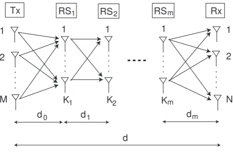
Fig. 1. Concept of multiple-hop MIMO relay system
Fig. 1 shows m relays intervened multi-hop MIMO relay system. Here, Ki (i = 0· · ·m+ 1) denotes the number of the antenna elements at the Tx, the Rx and each relay node.di (i= 0· · ·m)represents the distance between each transceivers. The distance between the Tx and the Rx is fixed as d. The signal is transmitted from the Tx to the RS1. At the RS1, the signal is decoded, encoded and transmitted to theRS2. Similarly, the signal is transmitted over and over until the signal reaches to the final receiver. We assumed the transmit power of the Tx (ET x) and the total transmit powers of relay node (ERS) are fixed regardless of the number of relay nodes and the number of antenna elements at each relay. The transmit power of each relay node is denoted byEi. Moreover, the transmit power of each relay is equally divided into each antenna element. In other site, as described in Section I, if the number of antenna elements at one relay is smaller than the other, this relay will be the bottleneck of system and the channel capacity of the system will be restricted by this relay. Since in this paper we consider the distance and transmit power, the number of antenna elements at each relay is assumed to be the same as that of theT x and the
Rxand be denoted by M.
Let Hii+1 denotes a Ki+1×Ki channel matrix between the RSi and the RSi+1. Since the path loss is taken into
consideration, Hii+1 is the composite matrix. We model
Hii+1 as
Hii+1= p
lii+1Hwii+1, i = 0,· · ·,m, (1)
whereHwii+1 is a matrix with independent and identically
distributed (i.i.d.), zero mean, unit variance, circularly symmetric complex Gaussian entries, and lii+1 represents the path loss between the RSi and the RSi+1. The path loss is described in detail in the following section. On the other hand, we assume the time-division-multiple-access (TDMA) algorithm is applied to control the trans-mission of each relay node. The allocation time for each relay in unit time is denoted byti,P
m
i=0ti= 1. Moreover, in order to explain controlling of distance and transmit power clearly, the treating of allocation time is left to the future work, in this paper allocation time of each relay node is assumed to be the same, ti= m1+1.
B. Path loss
Since there are a lot of obstacles, such as huge building, in propagation environment, the path loss is necessary to consider being attenuated by the reflection. The power of signal is reduced when the reflection is occurred. An amount of the reduction by one time of reflection is called reflection factor. It is natural that the reflection factor is changed according to matter of obstacles, the angle of reflections and so on. However, in this paper, the reflection factor of all reflections is assumed to be the same and denoted by a. The path loss between each transceivers is described in fig. 2. The path loss in this case is expressed as [11], [14]
li= (
λarefi 4πdi
)2, (2)
where refi is the number of reflection while a signal is transmitted between RSi and RSi+1. In addition, in order to obtain the number of reflection, the propagation environment coefficient Wi is defined as the average dis-tance from a reflection point to the next reflection point. In other words, it is the average of line-of-sight (LOS) distance between RSi andRSi+1. Therefore, the number of reflection between each transceivers can be expressed as refi = Wdii. Consequently, the path loss in (2) can be rewritten as
li = (
λa
di Wi
4πdi
)2. (3)
C. Signal to noise ratio
The transmission in multi-hop relay system is assumed to be controlled accurately. Therefore, when the signal Si−1 is transmitted from the RSi−1, the received signal at the RSi is expressed as [11], [12], [13]
Si =Hi−1i p
Pi−1Si−1+ni. (4)
Here, Pi =diag(pi1, pi2,· · ·, piKi)is the transmit power
matrix and be assumed to be subject to a constraint
T r(Pi) =
ET x (i= 0),
Ei (i6= 0),
whereT r(·)andpijdenote the trace and transmit power of
jth antenna element ofRSi, respectively. ni is the noise vector with i.i.d., zero mean, σ2 variance. The transmit power of every antennas in the same relay node was assumed to be equal.
pi1=pi2=· · ·=piKi = Ei
M.
In order to avoid that some nodes become the bottleneck and to obtain high channel capacity, the channel capacity of each node should be equal. Consequently, the received SNR of each node is necessary to be equal.
SN Ri =SN Rj, f or i6=j, i, j= 0· · ·m, (5) here,
SN R0 =
ETxl0
M σ2 , (6)
SN Ri =
Eili
M σ2, with i= 1· · ·m. (7) III. BEROF MULTIPLE-HOPMIMORELAY SYSTEMS
A. BER of every hop
The BER after modulation is as follows [15]
pi=αerfc( s
SN Ri
M β ) i= 0· · ·m (8)
Where erfc is the complementary error function,α, βare the factor based on the modulation scheme and summa-rized in Table I.
TABLE I
FACTORSα, βOF SEVERAL MODULATION SCHEMES
Modulation scheme α β index
BPSK 1/2 1 1
QPSK 1/2 2 2
8PSK 1/3 1/sin2(π/8) 3
16QAM 3/8 10 4
64QAM 7/24 42 6
256QAM 15/64 170 8
In order to improve the quality of service (QoS) of system, the channel code is applied. In this work, we investigate the effect of BER at every hop on QoS of whole system whether the QoS of every hop. Therefore, any channel code can be used as an example to analyze of performance and the wellknown (63, 57) Bose -Chaudhuri - Hocquenghem (BCH) is applied. The other parameter of BCH code as shown in Table II can be used
instead of (63, 57), the result is discussed in the following section. Due to application of the BCH code, the BER after decoding at the RSi is described as follows [16].
BERi= m X
j=t+1
m j
pji(1−pi)m−j, (9)
where m and t denote the block length and the error correction capability of BCH code, respectively.
TABLE II PARAMETER OFBCHCODE
m h t m h t m h t
7 4 1 63 39 4 127 92 5
15 11 1 36 5 85 6
7 2 30 6 78 7
5 3 24 7 71 9
31 26 1 18 10 64 10
21 2 16 11 56 11
16 3 10 13 50 13
11 5 7 15 43 14
6 7 127 120 1 36 15
63 57 1 113 2 29 21
51 2 106 3 22 23
45 3 99 4 15 27
8 31
Herehdenotes the number of information bits in every block code. Thus, the code rate,r, becomes r= mh.
B. BER of multiple-hop MIMO relay system
b b b b
-b -b -b
TX RS RS RS
-b RX
BER
BER m-1 BER
BER
BER m-1
BER
m
1-BER
1-BER 1-BER
1-BERm-1 1-BERm-1
1-BERm BER
m 1-BERm b 0
0
1
1 1
1
[image:3.595.335.523.275.418.2]1 2 m
Fig. 2. State transition diagram of an information bit b
represented as follows.
BER =
m X
i=0
(BERi m Y
j6=i
(1−BERj)) (10)
+
m X
i6=j6=k
(BERiBERjBERk m Y
l6=i,j,k
(1−BERl))
+· · ·
However, the BER of any link is much smaller than 1, therefore we can ignore three (3) or over power to BER and the BER of whole system is rewriten by
BER=
m X
i=0
BERi−2 m X
i6=j
BERiBERj. (11)
IV. PERFORMANCE EVALUATION
In order to evaluate the calculation method of BER in the previous section, the BER of system is calculated base on system parameters in Table III. The calculation result of QPSK and 8PSK modulation schemes is represented in Fig. IV.
TABLE III SYSTEM MODEL
Transmit power of TXPtx 100[mW]
Total transmit power of RSsPrs 100[mW]
Number of antennas M 4
Noise powerσ2 -102[dBm] Distance from source to destination d 3000[m] Propagation environment coefficientWi 1000[m] Reflectioni factor a -8 [dBm]
0 5 10 15 20 25 30
10-3 10-2 10-1
Number of relays: m
BER
8PSK
[image:4.595.70.301.156.237.2]QPSK
Fig. 3. BER of system
Understandably, the BER of QPSK is smaller meaning better than that of 8PSK, however we would like to focus on the optimal number of relays in the sense of the best BER of whole system. In case of QPSK, the optimal number of relays is five (5) whereas it is nine (9) in case of 8PSK. The reason of existing of optimal number of relay is as follows. For any modulation scheme, if the number of relays is small, the distance between transceiver is long, therefore the SNR is low and then the BER at every relay is bad. However, if the number of relays is over it’s optimum, the transmits power of every transmitter is low, and then the BER of every relay also is bad. Moreover, the BER of whole system approximates the sum of BER at every receiver. As a result the BER of whole system is bad when the BER of every relay becomes worse.
V. CONCLUSION
In this paper, we examined the performance of multiple-hop MIMO relay systems with the decode-and-forward method and derive the equation to calculate the BER of whole system. The relation between BER and the number of relays was discussed and the optimal number of relays that has the minimal BER of whole system is analyzed. The calculation result of only QPSK and 8PSK modulation scheme with (63,57) BCH code was represented, however the proposed method can calculate for further modulation schemes and code words.
However, in this paper, the channel capacity as well as the delay weren’t taken into consideration. All factors, such as BER of whole system, delay, channel capacity will be investigated to find out the optimal number of relays, modulation scheme and code word in our future work.
REFERENCES
[1] K.Miyashita, T.Nishimura, T.Ohgane, Y.Ogawa, Y.Takatori, and K.Cho, ”High data-rate transmission with eigenbeam space division multiplexing(E-SDM) in a MIMO channel,” Proc.IEEE VTC 2002-Fall, vol.3, pp.1302-1306, Sept. 2002.
[2] J.B.Andersen, ”Array gain and capacity for known random channels with multiple element arrays at both ends,” IEEE J.Set.Areas Commun., vol18, no.11, pp.2172-2178, 2000.
[3] J.F.Kepler, T.P.Krauss, and S.Mukthavaram, ”Delay spread mea-surements on a wideband MIMO channels at 3.7GHz,” 2002 IEEE VTC-Fall, Vancouver, Sept. 2002.
[4] D.S.Shiu, G.J.Foschini, M.J.Gans, and J.M.Kahn, ”Fading correla-tion and its effect on the capacity of multielement antenna systems,” IEEE Trans. Commun., vol48, no.3, pp.502-513, 2000.
[5] D.Chizhik,G.J.Foschini,M.J.Gans,and R.A.Valenzuela, ”Keyholes, correlations, and capacities of multielement transmit and receive antennas,” IEEE Trans. Wireless Commun., vol.1, no.2, pp.361-368, 2002.
[6] D.Gesbert, H.Bolcskei, D.A.Gore, and A.J.Paulraj, ”MIMO wireless channel: Capacity and performance prediction,” Proc. GLOBE-COM, vol.2, pp.1083-1088, Nov/Dec. 2000.
[7] B.Wang, J.Zhang, and A.host-Madsen, ”On the capacity of MIMO relay channel,” IEEE Trans.Inf.Theory, vol.51, no.1, pp.29-43, Jan. 2005.
[9] V.Tarokh, N.Seshadri, A.R.Calderbank, ”Space-time codes for high data rate wireless communication: Performance critrion and code constraction,” IEEE Trans. Inf.Threory, vol.44, no.2, pp.744-765, 1998.
[10] Makoto Tsuruta, Tetsuki Taniguchi, and Yoshio Karazawa, ”On statistical Distribution of Eigenvalues of channel correlation ma-trix in MIMO multi-Keyhole environment,” IEICE Trans.Commun, vol.E90-B, no.9 Sept.2007.
[11] Pham Thanh hiep, Kohno Ryuji, Ono Fumie, Optimizing Distance, Transmit Power and Allocation Time for Reliable Multi-Hop Re-lay System, EURASIP Journal on Wireless Communications and Networking, 2012
[12] Pham Thanh Hiep, Ryuji Kohno, Water-filling for full-duplex multiple-hop MIMO relay system, EURASIP Journal on Wireless Communications and Networking 2014, 2014:174, 2014
[13] Pham Thanh Hiep, Vu Van Son, Nguyen Huy Hoang, Channel Capacity Delay Tradeoff for Two-Way Multiple-Hop MIMO Relay Systems, In proceeding of The 12th IEEE VTS Asia Pacific Wireless Communications Symposium (APWCS), Singapore, 2015. [14] Naoki Kita, Wataru Yamada, Akio Sato, ”Path loss prediction model for the over-rooftop propagation environment of microwave band in suburban areas,” (in Japanese) IEICE Trans.Commun, vol.J89-B, no.2, pp.115-125, 2006.
[15] J.G.Proakis, ”Digital Communication”, McGraw-Hill.3rdEdition,
1995