i
WEARABLE EXOSKELETON SYSTEMS
BASED-ON PNEUMATIC SOFT ACTUATORS
AND CONTROLLED BY PARALLEL
PROCESSING
Hassanin Shaker Husein Al-Fahaam
Autonomous Systems and Robotics Centre
School of Computing, Science & Engineering
University of Salford, Salford, UK
Submitted in Partial Fulfilment of the Requirements of
the Degree of Doctor of Philosophy
ii
PUBLICATIONS
1- Al-Fahaam, H., Davis, S., & Nefti-Meziani, S. (2016). Power Assistive and Rehabilitation Wearable Robot based on Pneumatic Soft Actuators. Paper presented at the Methods and Models in Automation and Robotics (MMAR), 2016 21th ieee International Conference in Międzyzdroje, Poland.
2- Al-Fahaam, H., Davis, S., & Nefti-Meziani, S. (2016). Wrist rehabilitation exoskeleton robot based on pneumatic soft actuators. Paper presented at the International Conference for Students on Applied Engineering (ISCAE), , Newcastle upon Tyne, UK.
3- Al-Fahaam, H., Davis, S. and Nefti-Meziani, S., 2018. The design and mathematical modelling of novel extensor bending pneumatic artificial muscles (EBPAMs) for soft exoskeletons. Robotics and Autonomous Systems, 99, pp.63-74.
4- Hassanin, A.F., Steve, D. and Samia, N.M., 2017, September. A novel, soft, bending actuator for use in power assist and rehabilitation exoskeletons. In 2017 IEEE/RSJ International Conference on Intelligent Robots and Systems (IROS) (pp. 533-538). IEEE.
5- Al-Fahaam, H., Nefti-Meziani, S., Theodoridis, T. and Davis, S., 2018. The Design and Mathematical Model of a Novel Variable Stiffness Extensor-Contractor Pneumatic Artificial Muscle. Soft robotics, 5(5), pp.576-591.
6- Al-Fahaam, H., Davis, S., Nefti-Meziani, S. and Theodoridis, T., 2018. Novel soft bending actuator-based power augmentation hand exoskeleton controlled by human intention. Intelligent Service Robotics, 11, pp.247-268.
iii
CONTENTS
PUBLICATION II
CONTENTS III
LIST OF FIGURES VIII
LIST OF TABLES XIV
ABBREVIATIONS XV
PARAMETERS AND VARIABLES XVIII
ACKNOWLEDGEMENTS XIX
ABSTRACT XX
1 INTRODUCTION 1
1.1 Overview 1
1.2 Research Motivation 2
1.3 Aims and Objectives 2
1.4 Methodology 4
1.5 List of Contributions 4
1.6 Organisation of The Thesis 7
2 UPPER-LIMB POWER-ASSISTIVE AND/OR REHABILITATION ROBOTS 9
2.1 Introduction 9
2.2 Upper-Limb Anatomy 10
2.2.1 Human Shoulder Joint Motion 11
2.2.2 Human Elbow Joint Motion 11
2.2.3 Human Wrist Joint Motion 11
2.2.4 Human Hand Fingers Joints Motion 12
2.3 Power Assistive and/or Rehabilitation Robots 13
2.3.1 Power Assistive and/or Rehabilitation Robots using Electric Actuators 13
2.3.2 Power Assistive and/or Rehabilitation Robots using Hydraulic Actuators 16
2.3.3 Power Assistive and/or Rehabilitation Robots using Pneumatic Soft Actuators 19
iv
3. SOFT ACTUATORS 26
3.1 Introduction 26
3.2 Soft Actuator Techniques 27
3.2.1 Shape-Memory Alloys (SMAs) 27
3.2.2 Ionic Polymer-Metal Composites (IPMCs) 30
3.2.3 Dielectric-Elastomer Actuators (DEAs) 33
3.2.4 Pneumatic Elastomeric Actuator 34
3.3 Pneumatic Artificial Muscles 37
3.3.1 Construction 38
3.3.2 Operation 39
3.4 PAM Properties 39
3.5 Types and Classification 41
3.5.1 McKibben Muscle 41
3.5.2 Sleeved Bladder Muscle 41
3.5.3 Netted Muscles 42
3.5.4 Pleated PAM 43
3.5.5 Parallel Bladders artificial muscles 43
3.5.6 Concentric Bladders artificial muscles 44
3.6 Modelling 44
3.6.1 Geometrical Model of PMA 45
3.6.2 PAMs’ Phenomenological Model 46
3.6.3 Curved PMA Model 46
3.6.4 Empirical Model of PMA 47
3.7 Control 47
3.7 PAMs Applications 49
3.7 Conclusion 50
4. THE DESIGN AND MATHEMATICAL MODEL OF A NOVEL VARIABLE STIFFNESS EXTENSOR-CONTRACTOR PNEUMATIC ARTIFICIAL MUSCLE
(ECPAM) 52
4.1 Introduction 52
4.2 Contraction Pneumatic Artificial Muscles 53
v
4.4 Novel Extensor-Contractor Pneumatic Artificial Muscles (ECPAM) 59
4.4.1 Design and Construction of the ECPAM 60
4.4.2 Kinematics Analysis of ECPAM 63
4.4.3 Modelling the Output Force of the ECPAM 66
4.4.4 Experimental Verification of the ECPAM Output Force Model 67
4.4.5 Stiffness of the ECPAM 71
4.6 Stiffness and Position (length) Control of the ECPAM 73
4.7 Conclusions 81
5. THE DESIGN AND MATHEMATICAL MODELLING OF NOVEL EXTENSOR-BENDING PNEUMATIC ARTIFICIAL MUSCLES (EBPAMS) 83
5.1 Introduction 83
5.2 Extensor-Bending Pneumatic Artificial Muscles 84
5.3 Kinematic Analysis of the Proposed EBPAM 89
5.4 Modelling the Output Force of the Proposed EBPAM 92
5.5 Enhancements to the Mathematical Model based-on Radial Expansion Pressure 95
5.6 Enhancements to the Mathematical Model based on Actual Diameter 104
5.7 Enhancements to the Mathematical Model based on Total Volume 105
5.8 Conclusion 111
6. POWER ASSISTIVE AND AUGMENTATION WEARABLE ROBOT BASED
ON SOFT ACTUATORS 115
6.1 Introduction 115
6.2 Power Assistive Soft Glove 116
6.2.1 The Glove Characteristics 116
6.2.2 Output Force of the Proposed Prototype 118
6.2.3 Sensing 118
6.2.4 Proposed Solution for the Release Movement Problem 119
6.2.5 Proposed Control Algorithm 120
6.3 Power Augmentation Hand Exoskeleton based-on Human Intention 121
6.3.1 The Proposed Control Algorithm with Experimental Results 125
6.3.2 The Position Controller System 126
vi
6.3.2.2 The Fuzzy Logic Controller of the Position Controller 127
6.3.3 The Force Controller System 129
6.3.4 The Validation of the Proposed Exoskeleton and its Controller 134
6.4 Conclusion 139
7. UPPER-LIMB REHABILITATION EXOSKELETONS 140
7.1 Introduction 140
7.2 Hand Rehabilitation Exoskeletons 141
7.2.1 Hand Rehabilitation Exoskeletons (Version 1) 141
7.2.2 Hand Rehabilitation Exoskeletons (Version 2) 142
7.2.2.1 The Novel Controllable Stiffness Bending Actuators 144
7.2.2.2 The Proposed Exoskeleton Glove 145
7.2.2.3 The Proposed Controller System 145
7.2.3 Hand Rehabilitation Exoskeletons (Version 3) 156
7.2.3.1 The Proposed Variable Stiffness Soft Actuators 157
7.2.3.2 The Proposed Exoskeleton Glove 158
7.3 Forearm Rehabilitation Exoskeleton 162
7.4 Elbow Rehabilitation Exoskeleton 163
7.4.1 Modifications to the Elbow Rehabilitation Exoskeleton Actuation System 169
7.5 Wrist Rehabilitation Exoskeletons 170
7.5.1 Modifications to the Wrist Rehabilitation Exoskeleton Actuation System 173
7.6 Conclusion 176
8. PARALLEL PROCESSING BASED ON ON-CHIP CONTROLLERS FOR A
TOTALLY PORTABLE EXOSKELETON 177
8.1 Introduction 177
8.2 Field-Programmable Gate Array (FPGA) 178
8.2.1 FPGA DE0-NANO 179
8.2.2 Fuzzy logic controller on FPGA DE0-NANO 179
8.2.2.1 Fuzzification Stage 181
8.2.2.2 Inference-Engine Stage 183
8.2.2.3 Defuzzification Stage 184
vii
8.2.2.5 Pulse width modulation generator 185
8.2.2.6 Finite State Machine (FSM) 185
8.2.2.7 Clock Divider 185
8.3 Portable Air Supply 185
8.4 Totally Portable Rehabilitation System 186
8.5 Conclusion 188
9. CONCLUSION AND FUTURE WORK 190
9.1 Conclusion 190
9.2 Future Work 194
BIBLIOGRAPHY 196
viii
LIST OF FIGURES
Figure 1.1: Stages of Research Methodology 5
Figure 2.1: Human upper-limb anatomy 10
Figure 2.2: Shoulder joint movements 11
Figure 2.3: Elbow joint movements 12
Figure 2.4: Wrist joint movements 12
Figure 2.5: The human fingers and their joints 13
Figure 2.6: Power Assistive and/or Rehabilitation Robots using Electric Actuators 16
Figure 2.7: Power Assistive and/or Rehabilitation Robots using Hydraulic Actuators 18
Figure 2.8: Exoskeletons 19
Figure 2.9: Two Joints Power Assisted Glove 20
Figure 2.10: Power-assist glove 21
Figure 2.11: Power Assist System for a Manual Worker 22
Figure 2.12: Soft Gloves 23
Figure 3.1: Examples of muscular hydrostats and hydroskeletons 27
Figure 3.2: Working mechanism of SMAs 28
Figure 3.3: SMA actuators 29
Figure 3.4: SMA robotic applications 30
Figure 3.5: Operation of IPMCs 31
Figure 3.6: IPMC actuators 32
Figure 3.7: IPMC robotic applications 32
Figure 3.8: Robotic applications based on DEAs 34
Figure 3.9: Working mechanism of a pneumatic elastomeric actuator 35
Figure 3.10: A pneumatic elastomeric actuator showing bending motion 35
Figure 3.11: A legged robot using a pneumatic elastomeric actuator 36
Figure 3.12: An untethered fish robot using pneumatic elastomeric actuators 37
Figure 3.13: The PMA Construction 38
Figure 3.14: Operation of PAM 39
Figure 3.15: Antagonistic set-up 40
Figure 3.16: McKibben Muscle 41
Figure 3.17: Sleeved Bladder Muscle 42
ix
Figure 3.19: Pleated Pneumatic Artificial Muscle 43
Figure 3.20: Parallel Bladders artificial muscle 43
Figure 3.21: Concentric Bladders artificial muscle 44
Figure 3.22: Phenomenological Model 46
Figure 3.23: Similarity between a PAM and a mechanical spring 47
Figure 3.24: Control strategies diagram 47
Figure 3.25: PAMs Applications 50
Figure 4.1: The contraction artificial muscle with no-load at different pressures 54
Figure 4.2: No-load displacement characteristic of the contraction muscle with increased
applied pressure 54
Figure 4.3: Experiment setup to calculate the stiffness of the PAM 55
Figure 4.4: The experimental results of the contraction muscle change in length with
different attached loads at specific amounts of supplied pressure 55
Figure 4.5: The contraction muscle stiffness in relation with increasing the supplied
pressure 56
Figure 4.6: The Extensor artificial muscle with no-load at different pressures 57
Figure 4.7: No-load displacement characteristic of the extensor muscle with increased
applied pressure 57
Figure 4.8: The experimental results of the contraction muscle change in length with
different attached loads at specific amounts of supplied pressure 58
Figure 4.9: The extensor muscle stiffness in relation with increasing the supplied pressure 58
Figure 4.10: Construction and operation of the novel ECPAM 61
Figure 4.11: The experimental results of the relation between the ECPAM and increasing
the supplied pressure for the inner and outer muscles independently 62
Figure 4.12: The general geometry of PAM 63
Figure 4.13: Kinematics of the ECPAM 64
Figure 4.14: Experiment setup to calculate the extension and contraction force of the
ECPAM 68
Figure 4.15: The Experimental results of the output force of the ECPAM with its
mathematical model 69
Figure 4.16: The Experimental results of the output force of the ECPAM with its
mathematical model with consideration of correction factor 70
Figure 4.17: Stiffness experimental results for the ECPAM at length 16cm 72
x
Figure 4.19: MATRIX 3/3 750 series solenoid valve 75
Figure 4.20: The solenoid valve driver circuit 75
Figure 4.21: The pressure sensor circuit 75
Figure 4.22: The membership functions for the inputs and outputs for the Fuzzy controllers
of the proposed stiffness and position controller of the ECPAM 76
Figure 4.23: The Fuzzy controllers rules surfaces of each Fill and Vent outputs 77
Figure 4.24: Stiffness-position controller results at actuator length 15cm and two different
stiffness 78
Figure 4.25: Stiffness-position controller results at actuator length 16cm and two different
stiffness values 79
Figure 4.26: Stiffness-position controller results at actuator length 17cm and two different
stiffness values 80
Figure 5.1: EPAM length related to the supplied pressure 85
Figure 5.2: EBPAM pressurised by different amounts of pressure 85
Figure 5.3: EBPAM bending angle with the supplied pressure 86
Figure 5.4: M2 with its characteristics 87
Figure 5.5: M3 with its characteristics 88
Figure 5.6: Bending muscle geometry 90
Figure 5.7: Radii inside curved muscle 92
Figure 5.8: EBPAM output force direction 93
Figure 5.9: Test rig used to measure muscle force at a range of bending angles 95
Figure 5.10: Measured and modelled force for muscle M1 at 90°, 135° and 45° bend angle 96
Figure 5.11: Measured and modelled force for muscle M2 at 90°, 135° and 45° bend angle 97
Figure 5.12: Measured and modelled force for muscle M3 at 90°, 135° and 45° bend angle 98
Figure 5.13: Pressure needed to inflate the bladder tube 99
Figure 5.14: Pressure needed to inflate rubber 99
Figure 5.15: Final results of the output force for M1 in consideration with 𝑃𝑟 101
Figure 5.16: Final results of the output force for M2 in consideration with 𝑃𝑟 102 Figure 5.17: Final results of the output force for M3 in consideration with 𝑃𝑟 103 Figure 5.18: Final results of the output force for M1 in consideration with 𝑡𝑎 106
xi
Figure 5.21: The frustum of cone geometry with its parameters 109
Figure 5.22: The proposed extensor bending muscle new geometry with its parameters 109
Figure 5.23: Final results of the output force for M1 in consideration with 𝑉𝑙 112 Figure 5.24: Final results of the output force for M2 in consideration with 𝑉𝑙 113 Figure 5.25: Final results of the output force for M3 in consideration with 𝑉𝑙 114
Figure 6.1: Proposed soft glove; (a) The design and (b) The real prototype 117
Figure 6.2: Glove sensors 118
Figure 6.3: Control system 120
Figure 6.4: Proposed control flowchart 122
Figure 6.5: Hand EMG signals 123
Figure 6.6: The proposed power augmentation exoskeleton 124
Figure 6.7: The flowchart of the proposed control algorithm 126
Figure 6.8: The block diagram of the proposed position controller system 126
Figure 6.9: Results of the neural network identifier and the error of the targets and outputs 127
Figure 6.10: The membership functions for the inputs and outputs for the Fuzzy controller
of the proposed position controller 128
Figure 6.11: Fuzzy controller rules surface for each fill and vent output of the proposed
position controller 129
Figure 6.12: The experimental results of the position controller system 130
Figure 6.13: The proposed force controller 131
Figure 6.14: The membership functions for the inputs and outputs for the Fuzzy controller
of the proposed force controller 132
Figure 6.15: Fuzzy controller rules surface for each fill and vent output of the proposed
force controller 132
Figure 6.16: The experimental results of the force controller system 133
Figure 6.17: The validation experiment of the proposed prototype at grasping bending
angle approximately 120o 135
Figure 6.18: EMG signals analysis of grasping an object with a 120o bending angle of the
human hand 137
Figure 6.19: The validation experiment of the proposed prototype at grasping bending
angle of approximately 90o 138
Figure 6.20: EMG signals analysis of grasping an object with a 90 bending angle of the
human hand 139
xii
Figure 7.2: EMG signals of pinching load 143
Figure 7.3: EMG signals of grasping load 143
Figure 7.4: Patients with finger functionality disabled 143
Figure 7.5: The novel controllable stiffness bending actuator 144
Figure 7.6: Rehabilitation glove based on controllable stiffness bending muscles 145
Figure 7.7: Soft controller gloves 146
Figure 7.8: The hardware controller system 147
Figure 7.9: The fuzzy controller system for each actuator 147
Figure 7.10: Membership function of the fuzzy controller 148
Figure 7.11: The surface of the fuzzy controller 148
Figure 7.12: Hand rehabilitation movements controlled by a therapist’s hand 149
Figure 7.13: Hand rehabilitation controller results 150
Figure 7.14: The Matlab application foreground 151
Figure 7.15: Offline controllers results 152
Figure 7.16: The glove validation (Thumb finger) with step setpoint 153
Figure 7.17: The glove validation (Thumb finger) with sinusoidal setpoint 154
Figure 7.18: The glove validation (Index finger) with step setpoint 154
Figure 7.19: The glove validation (Index finger) with sinusoidal setpoint 155
Figure 7.20: The glove validation (Middle finger) with step setpoint 155
Figure 7.21: The glove validation (Middle finger) with sinusoidal setpoint 156
Figure 7.22: Hand movements 156
Figure 7.23: Partially variable stiffness soft actuator 158
Figure 7.24: Fully variable stiffness soft actuator 159
Figure 7.25: The proposed exoskeleton glove version 3 160
Figure 7.26: Typical hand rehabilitation exercises 161
Figure 7.27: The proposed forearm soft exoskeleton 162
Figure 7.28: The forearm supination using the soft exoskeleton 163
Figure 7.29: The forearm pronation using the soft exoskeleton 163
Figure 7.30: Elbow exoskeleton 164
Figure 7.31: Elbow medical bands with flex bend sensors 164
Figure7.32: Online controller for the elbow exoskeleton 165
Figure 7.33: The online controller results of the elbow exoskeleton 165
Figure 7.34: Offline elbow rehabilitation application 165
xiii
Figure 7.36: The Elbow exoskeleton validation (45o bending angle) with step setpoint 167
Figure 7.37: The Elbow exoskeleton validation (90o bending angle) with step setpoint 167
Figure 7.38: The Elbow exoskeleton validation (135o bending angle) with step setpoint 168
Figure 7.39: The glove validation (Thumb finger) with sinusoidal setpoint 168
Figure 7.40: Vertical and horizontal elbow rehabilitation exercises 169
Figure 7.41: The BBPAM operation 170
Figure 7.42: Kinematics of Wrist Motion 171
Figure 7.43: The proposed wrist soft exoskeleton 172
Figure 7.44: The rehabilitation movements of the proposed wrist soft exoskeleton 173
Figure 7.45: The ABPAM operation 174
Figure 7.46: Wrist rehabilitation exoskeleton based on ABPAM 175
Figure 7.47: Wrist rehabilitation exercises based on the new version of the wrist
rehabilitation prototype 175
Figure 8.1: FPGA chip 179
Figure 8.2: The DE0-Nano Board 180
Figure 8.3: Block diagram of DE0-Nano Board 180
Figure 8.4: Fuzzy logic controller (FLC) system 181
Figure 8.5: Complete VHDL design 181
Figure 8.6: Trapezoidal membership-degree 182
Figure 8.7: Flowchart of the fuzzification process 183
Figure 8.8: Air compressor design 186
Figure 8.9: Air compressor electronic circuit 187
xiv
LIST OF TABLES
Table 4.1: A summary of ECPAM’s stiffness results 73
Table 5.1: M1, M2 and M3 characteristics 86
Table 5.2: The average error as a percentage of the maximum actuator force with and
without consideration of Pr 100
Table 5.3: The average error as a percentage of the maximum actuator force with and
without consideration of ta 105
Table 5.4: The average error as a percentage of the maximum actuator force with and
xv
ABBREVIATIONS
ABPAM All Directional Bending Pneumatic Muscle Actuator
BBPAM Bidirectional Bending Pneumatic Muscle Actuator
BF Big Fill
BV Big Vent
CM Carpometacarpal
CPU Central Processing Unit
CVA Cerebrovascular Accidents
DC Direct Current
DEA Dielectric-Elastomer Actuators
DIP Distal Interphalangeal
DOF Degree Of Freedom
EBPAM Extensor Bending Pneumatic Artificial Muscle
ECPAM Extensor-Contractor Pneumatic Artificial Muscle
EMG Electromyography
EPAM Extensor Pneumatic Artificial Muscle
FEM Finite Element Model
FPGA Field-Programmable Gate Array
FSM Finite State Machine
IP Interphalangeal
IPMC Ionic Polymer-Metal Composite
M1 Muscle Number One
M2 Muscle Number Two
M3 Muscle Number Three
MAX Maximum amplitude
MP Metacarpophalangeal
NB Negative Big
NiTi Nickel-titanium
xvi
OCC On-Chip Controller
PAM Pneumatic Artificial Muscle
PB Positive Big
PD Proportional Derivative
PI Proportional Integral
PID Proportional Integral Derivative
PIP Proximal Interphalangeal
PMA Pneumatic Muscle Actuator
PMDPM Parallel Manipulator Driven by Pneumatic Muscle
PPAM Pleated Pneumatic Artificial Muscle
PS Positive Small
PWM Pulse Width Modulation
RMS Root Mean Square
SCI Spinal Cord Injuries
SD Standard deviation
SF Small Fill
SMA Shape-Memory Alloy
SNR Signal-to-Noise Ratio
SV Small Vent
VHDL High-Level Hardware Description Language
Z Zero
ZF Zero Fill
xvii
PARAMETERS AND VARIABLES
𝐿𝑜 Muscle Length Without Pressurization [m]
𝐿𝑛 Muscle Length Under Pressure [m]
∆L Change In Length [m]
L Muscle Length [m]
D Muscle Diameter [m]
θ Braid Angle [deg.]
b Sleeve Strand Length [m]
n Sleeve Strands Number
𝐷𝑐 Curved Muscle Diameter [m]
α Bend Angle Of The Muscle [deg.]
𝑟𝑜 Inner Radius Of Bending Muscle [m]
𝑟𝑛 Outer Radius Of Bending Muscle [m]
𝐿𝑐 The Bending Actuator Length [m]
𝜃𝑚𝑎𝑥 The Maximum Braid Angle [deg.]
𝑊𝑖𝑛 The Input Work [J]
𝑃′ Internal Absolute Air Pressure [Pa]
𝑃𝑜 Environment Pressure [Pa]
P Relative Differential Air Pressure [Pa]
𝑆𝑖 Actuator Inner Surface [m2]
𝑑𝑙𝑖 Inner Surface Displacement Vector [m]
𝑑𝑠𝑖 The Area Vector [m2]
𝑑𝑉𝑐 Actuator Volume Change [m3]
𝑉 Volume [m3]
xviii
𝑊𝑜𝑢𝑡 Output Work [J]
𝐹 Force [N]
𝑃𝑟 Radially Expand Lost Pressure [Pa]
𝑃𝑎 Actual Pressure [Pa]
𝐾𝑟 Linearized Radial Actuator Elasticity [KPa m ]
𝐷𝑜 Actual Bending Muscle Diameter [m]
𝑡𝑠 Sleeve Thickness [m]
𝑡𝑏 Bladder Thickness [m]
𝑡𝑎 Total Muscle Border Thickness [m]
𝐷𝑎 Muscle Actual Diameter [m]
𝑉𝑎 Bending Muscle Actual Volume [m3]
h Height [m]
r Radius Of The Lower Base [m]
R Radius Of The Upper Base [m]
𝑉𝑙 Deformation Volume [m3]
𝐿𝑙 Deformation Length [m]
d Actuator End Cap Diameter [m]
𝑉𝑡 Total Volume [m3]
xix
ACKNOWLEDGEMENTS
Undertaking this PhD has been a truly life-changing experience for me and it would
not have been possible without the support and guidance that I received from many people.
I would like to thank the Ministry of Higher Education in my country, Iraq, as well
as the University of Basrah, especially my department of Computer Engineering, who have
initiated, administrated and sponsored my study throughout this scholarship.
I wish to express my sincere thanks to my supervisor, Dr. Steven T. Davis, for his
constructive feedback, guidance and the freedom given to me in research matters.
Furthermore, I would like to convey my gratitude to the director of the Autonomous
Systems and Robotics Centre at the School of Computing, Science and Engineering, Prof.
Samia Nefti-Meziani, for her support and kindness.
Last but not least, I would like to express my deepest gratitude to my family and
friends. This dissertation would not have been possible without their warm love, continued
xx
ABSTRACT
Human assistance innovation is essential in an increasingly aging society and one
technology that may be applicable is exoskeletons. However, traditional rigid exoskeletons
have many drawbacks. This research includes the design and implementation of
upper-limb power assist and rehabilitation exoskeletons based on pneumatic soft actuators.
A novel extensor-contractor pneumatic muscle has been designed and constructed.
This new actuator has bidirectional action, allowing it to both extend and contract, as well
as create force in both directions. A mathematical model has been developed for the new
novel actuator which depicts the output force of the actuator. Another new design has been
used to create a novel bending pneumatic muscle, based on an extending McKibben
muscle and modelled mathematically according to its geometric parameters. This novel
bending muscle design has been used to create two versions of power augmentation gloves.
These exoskeletons are controlled by adaptive controllers using human intention. For
finger rehabilitation a glove has been developed to bend the fingers (full bending) by using
our novel bending muscles. Inspired by the zero position (straight fingers) problem for
post-stroke patients, a new controllable stiffness bending actuator has been developed with
a novel prototype. To control this new rehabilitation exoskeleton, online and offline
controller systems have been designed for the hand exoskeleton and the results have been
assessed experimentally. Another new design of variable stiffness actuator, which controls
the bending segment, has been developed to create a new version of hand exoskeletons in
order to achieve more rehabilitation movements in the same single glove. For Forearm
rehabilitation, a rehabilitation exoskeleton has been developed for pronation and supination
movements by using the novel extensor-contractor pneumatic muscle. For the Elbow
rehabilitation an elbow rehabilitation exoskeleton was designed which relies on novel
two-directional bending actuators with online and offline feedback controllers. Lastly for
upper-limb joint is the wrist, we designed a novel all-directional bending actuator by using
the moulding bladder to develop the wrist rehabilitation exoskeleton by a single
all-directional bending muscle. Finally, a totally portable, power assistive and rehabilitative
1
Chapter 1
Introduction
1.1 Overview
Human upper-limb robotic apparatuses can be broadly catergorised into two types:
prosthesis and orthosis. Prosthesis is an artificial body part, such as a hand or leg, that
disabled people can wear to replace a missing body part in order to help them in their daily
activities. Orthosis is an orthopaedic device that can be utilised to straighten alignment,
provide support to disabled individuals, or to provide a functionality improvement for
movable human body segments. In addition, orthosis devices are outside the human body
and provide a suitable external force to support the desired movement of the human limb
without considering individual joint movements of the limb. The most recent kind of
orthosis is the wearable robot, which is generally worn by the person. The joints and
connections of the wearable robot have lineal harmonisation with the individual joints and
limbs, respectively. Moreover, the robot axes are aligned with the anatomic axes of the
human limb. Wearable robots have been extensively researched in the fields related to
rehabilitation, assistance robots, human force augmentation, impairment evaluation, and
impedance exercises. Power assistive and rehabilitation robots have significantly increased
in number to assist physically weak, elderly individuals and disabled people who have
neurological damage, in order to improve their quality of life and independence. The
exoskeleton plays a significant role in providing comfort and safety for the wearer. The
physical human–robot interaction includes various aspects, such as transmission of power,
actuation, uniqueness, the degree of freedom (DOF), dexterity, compliance and kinematic
2
is in direct contact with patients and elderly individuals. It also needs to be a lightweight
device so that it can be portable and can be used at home without any clinical assistance. In
addition, it should be small and soft so as to be flexible in daily independent use. All of
these features are found in the pneumatic soft muscles used to build exoskeletons and
therefore many researchers depend on these soft actuators to manufacture power assistive
and/or rehabilitation wearable robots. Upper-limbs are the most common examples of
neurological weakness or damage because the worker’s hand is in direct contact with
machines and repetitive movements at work cause neurological damage, which then
produces a reduction in ability to control upper-limb muscles.
1.2 Research Motivation
In the future, with the increasing numbers of elderly people and the decreasing
birth-rate, there might not be sufficient working individuals in the different fields, such as
for medical well-being, cultivation and industry. In particular, the expansion of the elderly
population and the shortfall of caregivers will be an interesting challenge. To manage this
issue, it may be necessary to develop a device or robot to provide assistance to elderly
individuals, disabled persons, nurses, manual workers, caregivers, and so on. Human
assistive technology has now become a major concern and researchers in mechatronics and
robotics have become more interested in the relationship between the machine and the
human. Furthermore, rehabilitation and physical therapy are proven successful methods for
regaining the ability to control body motion for individuals with physical injuries,
neurological damage and different kinds of disabilities. The most widely recognised are
hand disabilities, because the manual worker’s hand is in direct contact with machines and
repeated motions at work can cause neurological damage which then produces a reduction
in capability to control hand muscles. All of these reasons have inspired and motivated
research into upper-limb power assistance and/or rehabilitation robots to solve these
problems.
1.3 Aims and Objectives
This research aims to develop power assistive and/or rehabilitation exoskeletons
based on pneumatic artificial muscles for human upper-limb segments (hands, fingers,
wrist joints and elbow joints). These exoskeletons, with novel actuators, mathematical
3
single device suitable for any person to wear), with high output force but safe for human
interaction.
To achieve these targets the following objectives are set:
1- Develop a novel Extensor-Contractor pneumatic artificial muscle.
2- Develop a kinematic analysis for the novel Extensor-Contractor actuator.
3- Develop a mathematical model for the novel Extensor-Contractor actuator output
force.
4- Design a novel soft bending actuator based on the extensor McKibben muscle.
5- Develop a kinematic analysis for the novel bending actuator.
6- Develop a mathematical model for the novel bending actuator output force and
enhance this mathematical model to decrease the error between the model and the
experimental results.
7- Construct a power assistive glove to provide augmentation force for the fingers
which is controlled by human intention; this glove could be used for elderly or
partially disabled individuals or for force augmentation for manual workers with
heavy work.
8- Design and construct a novel, fully soft (materials and actuation) rehabilitation
exoskeleton glove, fit for any adult and capable of assisting all hand rehabilitation
motions.
9- Develop and build a novel soft wearable robot for wrist power assistive
rehabilitation purposes; this device should be portable and capable of performing
all wrist movements including Flexion/Extension, Radial/Ulnar deviation and
circular movements.
10-Design and construct a novel soft wearable device for elbow and forearm power
assistive rehabilitation; this device should have the ability to assist the elbow
Flexion/Extension movements and forearm pronation and supination movements.
11-Design and implement a totally portable rehabilitation system based on parallel
processing controllers on-chip, with a small and lightweight air compressor as an
air pressure supply for the pneumatic rehabilitation system.
12-Critically evaluate the suitability of the soft exoskeleton system for safe human
4
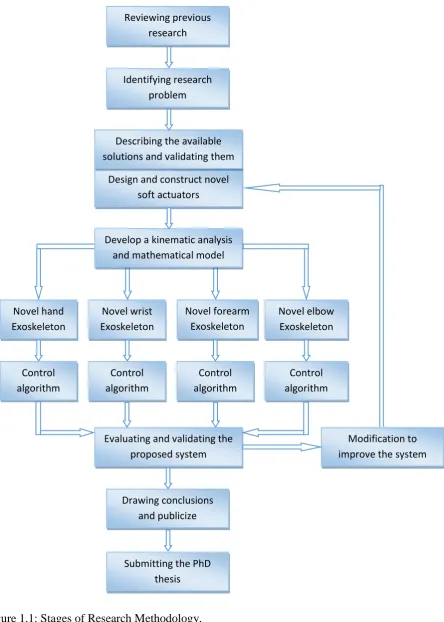
1.4 Methodology
The methodology that will be adopted in order to complete the present project will
involve the following steps: (Figure 1.1 shows the research methodology and its key steps).
1- Reviewing previous research: previous research which is related to power assistive
and/or rehabilitation devices and soft actuators or any relevant field has been
reviewed to understand the project area and construct a clear understanding about
the whole design system. This review has also provided us with good knowledge on
the different areas of research in the soft wearable robot systems.
2- Identifying the research problem: the first step in the research was identifying the
research problem by reviewing previous work and specifying the drawbacks in the
previous exoskeleton systems.
3- Describing the available solutions and validating those that are essential for
improving the performance of the wearable system.
4- Designing and constructing novel soft actuators.
5- Developing a kinematic analysis and mathematical model for these actuators.
6- Developing a novel soft exoskeleton design for each upper-limb segment.
7- Developing a suitable controller system for each exoskeleton part.
8- Evaluating and validating the proposed designs: the proposed design will be
evaluated by implementing an experimental evaluation of the system to assess its
effectiveness.
9- Ongoing modification of the design system based on the evaluation, to improve the
system performance and to optimise its design.
10-Finalising conclusions, publishing results and submitting a PhD thesis for
examination.
1.5 List of Contributions
1- Design and construct a novel extensor-contractor pneumatic artificial muscle
(ECPAM).
• This new actuator has bidirectional action allowing it to both extend and contract, as well as create force in both directions, with controllable
5
Figure 1.1: Stages of Research Methodology.
Novel wrist Exoskeleton Novel hand Exoskeleton Novel forearm Exoskeleton Novel elbow Exoskeleton Design and construct novel
soft actuators Control algorithm Control algorithm Control algorithm Control algorithm
Evaluating and validating the proposed system
Modification to improve the system
Drawing conclusions and publicize
Submitting the PhD thesis
Develop a kinematic analysis and mathematical model
Reviewing previous research
Identifying research problem
6 • A mathematical model has been developed for the new novel ECPAM
which describes the actuator output force.
• A stiffness position controller has been developed to control the stiffness of
the actuator (ECPAM) at specific lengths. Verification was conducted
using the controller and the average stiffness and position errors were
found to be less than 5%.
2- Design and construct novel extender bending pneumatic artificial muscles
(EBPAMs).
• Create kinematics analysis for EBPAM depending on its geometrical
parameters.
• Develop a novel axial output force mathematical model for EBPAMs, with
an average percentage error of 15.81% between experimental results and
our mathematical model.
• Enhance our mathematical model based on the loss of radial expansion pressure of the proposed actuators in order to obtain an average percentage
error reduction of 45.21% for our last model in previous point.
• Enhance our last mathematical model based on actual muscle diameter in
order to have an average percentage error reduction of 29.81% for our last
model in previous point.
• Enhance our last mathematical model based on the total muscle actual volume in order to have an average percentage error reduction of 22.64%
for our last model in previous point.
3- A new design for a power assistive glove for partially disabled individuals with a
novel solution for release movement problems after assistive has occurred.
4- A new design for a power augmentation glove for partially disabled or healthy
individuals with a novel hybrid, cascaded position/force intelligent control system,
based on human intention.
5- A fingers rehabilitation glove has been developed to bend the fingers by using our
novel bending muscles.
• To solve the zero position (straight fingers) problem for post-stroke patients, a new controllable stiffness bending actuator has been developed
7 • Online and offline controller systems have been designed for the hand
exoskeleton and the results have been assessed experimentally.
6- New designs of variable stiffness actuators to control the bending segment have
been developed to create a new version of hand exoskeletons in order to achieve
more rehabilitation movements in the same single glove, such as hook and table
fists.
7- A forearm rehabilitation exoskeleton has been developed for pronation and
supination movements.
8- The elbow rehabilitation exoskeleton is designed based on our novel bending
actuators with online and offline feedback controllers.
9- A novel two-directional bending actuator has been developed based on moulding a
bladder from elastic liquid materials. This bending actuator has been used to
enhance the elbow exoskeleton so as to make it capable of performing the
rehabilitation exercises vertically and horizontally with a controllable stiffness.
10-A wrist exoskeleton has been developed in order to perform the wrist rehabilitation
movements.
11-The novel all-directional bending actuator has been developed based on the
moulding bladder technique. This actuator is used to develop a new version of the
wrist rehabilitation exoskeleton.
12-Design and implementation of a totally portable rehabilitation system based on
parallel processing controllers on-chip.
1.6 Organisation of the thesis
This thesis is organised into nine chapters so as to present the different aspects of
the research that has been undertaken to complete the goals described above.
Chapter 1: Introduction : - This chapter presents a general overview of the power assistive
and rehabilitation exoskeleton. It then illustrates the research motivation, aims and
objective for this PhD research. It also explains the research methodology and lists
the thesis’ contributions.
Chapter 2: Upper-Limb Power-Assistive and/or Rehabilitation Robots : - This chapter
presents a review of previous research in the power assistance and rehabilitation
8 Chapter 3: Soft Actuators : - This chapter presents background information on soft
actuators, especially traditional PAMs, and discusses their numerous advantages
over other actuation technologies. Furthermore, current applications of PAM
actuators are briefly considered, along with the modelling efforts that have been
used thus far to predict the behaviour of these devices. Given the current state of
PAM technology and its analysis, motivation is established to develop novel PAM
actuators for new applications.
Chapter 4: The Design and Mathematical Model of a Novel Variable Stiffness
Extensor-Contractor Pneumatic Artificial Muscle (ECPAM) : - This chapter presents the
design of a novel Extensor-Contractor Pneumatic Artificial Muscle (ECPAM).
Furthermore, it contains the kinematics analysis of ECPAM with a mathematical
model for these actuators.
Chapter 5: The Design and Mathematical Modelling of Novel Extensor-Bending
Pneumatic Artificial Muscles (EBPAMs) : - This chapter presents the design of
novel Extensor Bending Pneumatic Artificial Muscles (EBPAMs) for soft
exoskeletons. Additionally, this chapter describes the design of the kinematic
analysis and mathematical model for these actuators.
Chapter 6: Power Assistive and Augmentation Wearable Robot Based on Soft Actuators : -
This chapter presents the design of soft, wearable gloves for power assistance and
augmentation based on pneumatic soft actuators.
Chapter 7: Upper-Limb Rehabilitation Exoskeletons : - This chapter presents the design
and construction of hand, forearm and wrist rehabilitation devices.
Chapter 8: Parallel Processing based on On-Chip Controllers for a Totally Portable
Exoskeleton : - This chapter presents the design and implementation of a totally
portable rehabilitation system based on parallel processing controllers on-chip.
Chapter 9: Conclusion and Future Work: - This chapter concludes the entire research and
9
Chapter 2
Upper-Limb Power-Assistive and/or
Rehabilitation Robots
2.1 Introduction
Robots are increasingly relied upon to promote efficient and enhanced living in
modern day society. It can lead to a major improvement in quality of life if a robot assists
and supports physically disabled and elderly individuals in their daily lives; for example, in
social participation, rehabilitation, nursing, agriculture, medical welfare and so on.
Furthermore, it is an increasing challenge to overcome the scarcity of caregivers for people
in need of care. Elderly and disabled individuals need to be able to live independently if
they so desire. In addition, rehabilitation and physical therapy are effective ways of
regaining the ability to control body movement for people with neurological damage,
physical injuries and other causes of disability. The most common are hand disabilities
because the worker’s hand is in direct contact with machines and repetitive movements at
work cause neurological damage which then produces a decrease in the ability to control
hand muscles. All the above reasons have inspired the invention of numerous kinds of
power assistance and rehabilitation robots to solve these problems.
This chapter describes the human upper-limb anatomy by demonstrating the joints
and movements of eachsegment in the upper-limb. A classification has been made for the
power assistive and/or rehabilitation devices depending on their actuation type, such as
10
review of previous research, drew conclusions from the literature review and discussed the
pros and cons of previous research and what the challenges were in this field.
2.2 Upper-Limb Anatomy
The human upper-limb consists of three parts: hand, forearm and upper-arm (see
Figure 2.1 a). The human hand consists of two segments: finger joints and wrist joints (see
Figure 2.1 b); each finger has three joints.
Figure 2.1 c shows shoulder and elbow segments. The shoulder segment has three
bones: the humerus, scapula and clavicle. The humerus is the longest bone in the
upper-limb of humans, extending from the shoulder to the elbow. The scapula, or shoulder blade,
consists of two flat triangular bones, each forming the back part of a shoulder in humans.
The clavicle, or collarbone, consists of two slender bones, each articulating with the
sternum and a scapula and forming the anterior part of a shoulder. The elbow is the bend or
joint of the human arm between the upper arm and forearm. The wrist is the carpus or
[image:30.595.147.462.410.722.2]lower part of the forearm where it joins the hand.
Figure 2.1: Human upper-limb anatomy (R. Gopura, D. Bandara, K. Kiguchi, & G. Mann,
11
2.2.1 Human Shoulder Joint Motion
The shoulder complex is the largest joint of the upper-limb and has three DOF
movements, as shown in Figure 2.2. Generally, there are three shoulder joint movements:
flexion (forward and upward movement of the humerus on the glenoid in the sagittal
plane)/extension (upward movement of the humerus on the glenoid in the sagittal plane
towards the rear of the body) (see Figure 2.2 a), abduction (elevation of the humerus on the
glenoid in the frontal (coronal) plane)/adduction (movement of the humerus on the glenoid
in a medial direction, usually accompanied with some degree of shoulder flexion) (see
Figure 2.2 b) and internal rotation (rotation of the humerus on the glenoid in a medial
direction)/external rotation (rotation of the humerus on the glenoid in a lateral direction)
(see Figure 2.2 c).
Figure 2.2: Shoulder joint movements (R. Gopura, D. Bandara, K. Kiguchi, & G. K. Mann,
2016b).
2.2.2 Human Elbow Joint Motion
The elbow is the middle joint of the arm between the wrist and the shoulder joints
and has two DOFs, as shown in Figure 2.3. Generally, the elbow joint has two movements:
flexion/extension (see Figure 2.3 a) and supination/pronation (see Figure 2.3 b).
2.2.3 Human Wrist Joint Motion
The wrist is the last joint before the fingers and the first after the elbow joint. It has
two DOF movements, as shown in Figure 2.4. Generally, the wrist joint has two
12
movements: flexion/extension (see Figure 2.4 a) and radial/ulnar deviation (see Figure 2.4
b).
Figure 2.3: Elbow joint movements (Gopura et al., 2016b).
Figure 2.4: Wrist joint movements (Gopura et al., 2016b).
2.2.4 Human Finger Joint Motion
Figure 2.5 shows the human fingers and their joints: index, middle, ring and pinky
fingers each contain three joints. The largest joint at the root of the finger is called the MP
joint (metacarpophalangeal joint). The middle joint of each finger is the PIP joint
(proximal interphalangeal joint). The terminal joint is called the DIP joint (distal
interphalangeal joint). The thumb also has three joints: the root joint at the back of the
palm is the CM joint (carpometacarpal joint). The middle joint has the same name as the
root joints in the fingers: the MP joint. Finally, the IP joint (interphalangeal joint) is the
name of the terminal joint of the thumb.
(a)
(b)
13
Figure 2.5: The human fingers and their joints.
2.3 Power Assistive and/or Rehabilitation Robots
During the last two decades, power assist and/or rehabilitation robots have been
attracting more interest (Rocon & Pons, 2011). There is abundant research in this field and
we can classify this research by the type of actuators used. The most common actuator
categories are: electric, hydraulic and pneumatic soft actuators.
2.3.1 Power Assistive and/or Rehabilitation Robots using Electric
Actuators
Electric actuators are gadgets controlled by engines that transform electrical energy
into mechanical torque. Due to no oil is included, electrical actuators are thought to be one
of the cleanest and most easily available types of actuators. There are numerous types of
electric actuators and their function is dependent on the motor that they use. Electric
actuators are commonly used to manufacture wearable robots for power assistance and
rehabilitation, and the following research studies are some examples of that:
Frisoli et al. (2005) designed an exoskeleton to support the human shoulder
movements and the elbow flexion/extension motions. This exoskeleton has 5 DOFs
actuated by 4 DC motor groups and the motor groups’ mass is approximately 40% of the
whole exoskeleton mass. The prototype has been optimised to solve the problem of high
mass and high stiffness in exoskeletons by using lightweight units, such as special carbon
fibre mechanical components (see Figure 2.6 a).
Nef, Mihelj, Colombo, and Riener (2006) presented an upper-limb exoskeleton
called ARMin. This device provides 6 DOF movements for the rehabilitation patients in
14
motors to reach the desired force and position for each rehabilitation movement. ARMin
has been tested with five patients for more than 30 hours and the test results were
extremely successful (see Figure 2.6 b).
Ball, Brown, and Scott (2007) developed a rehabilitation robot for stroke patients
called MEDARM. This exoskeleton is capable of providing 6 DOFs for shoulder and
elbow joints, actuated by electric motors with cables and belts to improve the
power-to-weight ratio of their exoskeleton. MEDARM provides most shoulder movements and one
for the elbow joint, and it can independently monitor and control all of its 6 DOFs (see
Figure 2.6 c).
Retolaza, Pujana-Arrese, Cenitagoya, Basurko, and Landaluze (2008) presented a
power assistive upper-limb exoskeleton device to support the manual worker in the
workplace, especially during routine or repetitive movements. Their design was developed
to amplify the shoulder and elbow motions with 5 DOFs actuated by a combination of
conventional electric motors and pneumatic artificial muscles (see Figure 2.6 d).
Ren, Park, and Zhang Sr (2009) developed a whole upper-limb exoskeleton for
fully paralysed stroke patients, especially for the hand and fingers gripping movement.
This exoskeleton has 10 DOFs with DC motors to serve the purpose of diagnosis,
treatment, training and outcome evaluation. Experimental results proved that this device
provides more accurate diagnosis results than the clinician (see Figure 2.6 e).
Rahman, Ouimet, Saad, Kenne, and Archambault (2010) designed a wearable robot
for rehabilitation purposes called ExoRob for the human shoulder and elbow joints.
ExoRob is an exoskeleton robot that has 2 DOFs to support the internal/external rotation
motion for the shoulder joint and the flexion/extension for the elbow joint. The researchers
also focused on the mathematical model and the control algorithm of their design. A
kinematic model type and nonlinear sliding mode controller were used (see Figure 2.6 f).
Ivanova, Bulavintsev, Ryu, and Poduraev (2011) proposed a 7 DOFs exoskeleton
placed on a wheelchair to serve elderly and disabled people. Their design was
manufactured to provide assistive movements for shoulder and elbow joints to perform the
activities of daily living efficiently. Many tests have been done to examine the mechanism
control performance of this prototype; the results were extremely encouraging (see Figure
15
Ergin and Patoglu (2012) introduced an exoskeleton device to the rehabilitation
exercises for shoulder and elbow segments called ASSISTON-SE. ASSISTON-SE, using
independent active control and designed to amplify the force movements of both passive
translational movements of the centre of the glenohumeral joint. Implementation details for
their prototype have been provided, as well as the results of numerous experiments done
for their prototype, to prove the ability of this device to track movements of the shoulder
girdle (see Figure 2.6 h).
J. A. Martinez, Ng, Lu, Campagna, and Celik (2013) designed and presented the
implementation and specifications of the forearm and wrist rehabilitation device for stroke
patients. This device provides 3 DOF movements for the wrist joint and forearm segment
to support pronation/supination, flexion/extension, and adduction/abduction joint motions.
Using three Maxon DC brush motors for actuation, the design focused on the safety
requirements by using mechanical rubber parts and an easily accessible emergency stop
switch (see Figure 2.6 i).
Yamamoto et al. (2014) developed a rehabilitation robot for supporting patients
when performing their rehabilitation exercises. This design is capable of detecting human
intentions and supports any movement of the wrist joint. This device is also small and
lightweight so that patients can use it in a clinic or at home. Actuator units receive a
biological signal from the muscles to decide which movement the patient needs (see Figure
2.6 j).
Xiang et al. (2015) presented a one DOF wrist and forearm rehabilitation device for
stroke patients. This device is capable of providing different training modes and creating a
virtual-reality game for the patient to perform during the training. The device had been
examined by two stroke patients and one chronic patient with left hemiplegia, and the
results were successful. The robot is reconfigurable to each rehabilitation mode and it is
portable (see Figure 2.6 k).
S. Chen et al. (2016) presented a rehabilitation robot called NTUH-ARM to rehabilitate the
human upper-limb. This robot has 7 DOFs actuated by FAULHABER DC motors to
perform most upper-limb rehabilitation exercises. Two 6-axis force/torque sensors have
been used to provide a movement capture for the monitor and the controller. This device
16
results were examined by physical therapists, also revealing promising results (see Figure
[image:36.595.85.535.118.487.2]2.6 l).
Figure 2.6: Power Assistive and/or Rehabilitation Robots using Electric Actuators: (a) The
arm exoskeleton (Frisoli et al., 2005); (b) ARMin exoskeleton (Nef et al., 2006); (c)
MEDARM system (Ball et al., 2007); (d) Exoskeleton Prototype IKO (Retolaza et al.,
2008); (e) A 8+2 DOF Robot (Ren et al., 2009); (f) Exoskeleton Robot (Rahman et al.,
2010); (g) Prototype of The 7-DOF (Ivanova et al., 2011); (h) Solid Model of
ASSISTON-SE (Ergin & Patoglu, 2012); (i) Wrist Gimbal (J. A. Martinez et al., 2013); (j) The
Prototype Rehabilitative Training Robot (Yamamoto et al., 2014); (k) CAD drawing of
The Robot (Xiang et al., 2015); (l) NTUH-ARM (S. Chen et al., 2016).
2.3.2 Power Assistive and/or Rehabilitation Robots using Hydraulic
Actuators
Hydraulic actuators consist of a cylinder or liquid engine that uses pressure driven
energy to facilitate mechanical operations. The mechanical movement produces an output
(c) (d)
(e) (f) (g) (h)
(i) (j) (k) (l)
17
involving linear, rotary or oscillatory movement. Because the fluids are approximately
incompressible, they take a long time to generate speed and force and, likewise, slow back
down. However, they can apply a large force. The hydraulic actuators are widely used to
create exoskeletons for power assist and rehabilitation, and the following studies are some
examples of that:
Mistry, Mohajerian, and Schaal (2005) proposed an experimental prototype to
study the human upper-limb in 3D motion. This prototype has a 7 DOFs hydraulically
actuated exoskeleton robot arm to examine the behaviour of human upper-limb motor
control. An independent PD servo controller has been used at each joint to create an
efficient control structure to fit most human upper-limb movements. Force field
experiments have been done to test the effectiveness of this device and the results were
promising (see Figure 2.7 a).
Pylatiuk et al. (2009) presented an elbow flexion orthosis device for rehabilitation
purposes with one DOF for the elbow joint. The major advantages of this device are that it
is lightweight, portable, safe and inexpensive to facilitate a patient’s independent usage at
home or at a clinic etc. A flexible fluidic actuation system has been used to actuate this
prototype. Surface EMG electrodes are used to control elbow flexion and extension
movements. The system is also designed to provide the extra elbow flexion force that
enables the patient to carry an additional load, such as a glass of water (see Figure 2.7 b).
Vitiello et al. (2013) proposed a powered elbow exoskeleton designed for
poststroke physical rehabilitation, ensuring maximum safety and comfort to the patient.
They used lightweight mechanical materials to minimise the pressure on the skin. This
device has 4 DOFs to drive elbow flexion and extension movements. These DOFs are
actuated hydraulically by using two cylinders and tendons to a suitable control for the joint
movements under rehabilitation training conditions (see Figure 2.7 c).
Polygerinos, Galloway, Sanan, Herman, and Walsh (2015) designed a power
assisted glove for full finger assistance for the activities of daily life. The glove is
manufactured in elastomeric and inextensible materials so as to be lightweight and to
create soft actuators that conform to the patient’s fingers and are able to create enough
hand grasp force. A fluidic pressure controller, which depends on human intentions, is used
to actuate and control the glove. The patient’s intention is detected by monitoring the EMG
18
Otten et al. (2015) developed a hydraulically powered self-aligning upper-limb
exoskeleton for identifying the reflex properties of the shoulder and elbow joints in stroke
patients. Powerful hydraulic motors are used to actuate this rehabilitation device and to
generate high torques and power using lightweight actuators. This exoskeleton is also used
for diagnostic purposes to diagnose the level of muscle/neurone damage in the upper-limb
(see Figure 2.7 e).
Polygerinos, Wang, Galloway, Wood, and Walsh (2015) presented a soft glove to
assist the rehabilitation exercises for functional grasp pathologies. The prototype employs
soft actuators consisting of moulded elastomeric chambers with fibre reinforcements that
produce suitable curvatures at finger joints under fluid pressurisation. A closed-loop
controller is used to regulate the pressure inside the actuators. This device is completely
portable with a rechargeable battery (see Figure 2.7 f).
Figure 2.7: Power Assistive and/or Rehabilitation Robots using Hydraulic Actuators: (a)
Exoskeleton Robot (Mistry et al., 2005); (b) Components of a Fluidically Driven Elbow
Training System Prototype (Pylatiuk et al., 2009); (c) NEUROExos (Vitiello et al., 2013);
(d) The fabricated soft robotic glove prototype (Polygerinos, Galloway, et al., 2015); (e)
LIMPACT (Otten et al., 2015); (f) The prototyped soft and lightweight robotic hand
assistive device (Polygerinos, Wang, et al., 2015).
(a) (b) (c)
(f) (e)
19
2.3.3 Power Assistive and/or Rehabilitation Robots using Pneumatic Soft
Actuators
Pneumatic soft actuators are actuators motored by air pressure created from soft
materials, such as rubber tubes acting as a bladder and braided sleeves. They are the safest
actuators for direct human interaction because they are lightweight and contain no rigid
parts.
Noritsugu, Yamamoto, Sasaki, and Takaiwa (2004) presented a power assistive
wearable glove to assist in making hand-gripping activities easier and safer in day to day
life (see Figure 2.8 (a)). McKibben type pneumatic artificial muscles (PAMs) were used,
placed on the front of the glove surface, one for each finger and two muscles for the palm
(thumb side), one on the back and the other one on the face of the hand. Curved type
PAMs are used by reinforcing one side of the muscle then, when pressurised, the muscle
will be curved on the reinforced side. This device used the expiration switch (like video
games controller switches) as the input signal since the expiration switch is generally
easily used by disabled patients. This work was developed by Sasaki, Noritsugu, and
Takaiwa (2005a) to manufacture a power assistive device for the wrist joint by also using a
PAMs rotary type soft actuator (see Figure 2.8 (b).
Figure 2.8: Exoskeletons: (a) Power Assist Glove (Noritsugu et al., 2004); (b) Assisting
Scene (Sasaki et al., 2005a); (c) Power Assist Splint (Noritsugu, 2005); (d) ASSIST
[image:39.595.189.423.460.697.2]20
This type of pneumatic soft actuator consists of a rubber tube, two silicone rubber
tubes and polyester bellows, which are reinforced with fibre to produce bending
movements. In order to develop this study, Noritsugu (2005) extended the previous wrist
assist device into an upper-limb splint to produce assistive power for the wrist and elbow
joints (see Figure 2.8 (c)). A power assistive device for the elbow joint was driven by a
contraction curved PAM attached to the elbow through a supporter, and the assistive force
was controlled by adjusting the pressure inside the muscle. Moreover, a control technique,
which takes into account a human aim, is proposed by Sasaki et al. (2005b) (see Figure 2.8
(d)). In the proposed technique, a focal point of pressure, calculated from the contact force
between the lower arm and appliance, is utilised as a human aim info signal and the
adequacy of the device is assessed utilising EMG.
A new design for power assistive wearable gloves has been developed by
Noritsugu, Takaiwa, and Sasaki (2008) using two joint muscles for each finger except the
[image:40.595.86.538.382.641.2]thumb (see Figure 2.9 (a)).
Figure 2.9: (a) Two Joints Power Assisted Glove (Noritsugu et al., 2008); (b) Power-Assist
Glove (Toya, Miyagawa, & Kubota, 2011).
Two curved type PAMs with different diameters are connected in series on the
back of each finger. The muscle with the smaller diameter is placed on the terminal two
21
by a split air supply. The advantage of this technique is its capability of controlling the
finger joints separately and to provide more movement types for assistance and
rehabilitation. Similar to this, a design with two joints for each finger has been made by
Toya et al. (2011), but this device used soft materials moulded to create the bending type
artificial muscles (see Figure 2.9 (b)). The controller of this design depends on human
intention as the input by using bending sensors attached to the muscles. In addition, the
movements are divided into only three modes: power grip, precision grip, and tip pinch;
the controller predicts the mode by matching the grasping angles with the stored database.
Another new design of a hand power assistive wearable robot was developed by
Kadowaki, Noritsugu, Takaiwa, Sasaki, and Kato (2011) (see Figure 2.10).
Figure 2.10: Power-assist glove (Kadowaki et al., 2011).
The design of this wearable robot is completely made up of soft materials, inspired
by McKibben's muscles. Each muscle has two bladders: a rubber one and one comprising a
balloon covered by woven elastic. These muscles are placed on the back of the hand, one
for each finger, except that the thumb has two muscles. PI controllers were used to decide
22
Estimated timing is used to perform the release movement after the gripping movement.
They tried to use the EMG signals to control the release movements but they faced a
problem due to the similarity between the EMG signals from the fingers and the wrist joint
movements. Improvements to the controller algorithm of this robot have been achieved by
(Sasaki, Noritsugu, Takaiwa, & Konishi, 2014). A neural network controller is used
(Self-Organizing Maps) to recognise the different EMG signals from the wrist and the fingers
during a release movement. However, this method assumed that the fingers and the wrist
move independently (if the fingers are moving, the wrist is fixed and vice versa).
The power assistive wearable robot is not only for disabled or elderly people, but
also for assisting with heavy manual work, such as nursing staff moving disabled patients
from/to hospital beds. Kobayashi, Suzuki, Nozaki, and Tsuji (2007) proposed a muscle suit
consisting of the upper-limb soft exoskeleton to provide muscular support for a manual
worker (see Figure 2.11 (a)).
Figure 2.11: (a) Power Assist System for a Manual Worker by using a Muscle Suit
(Kobayashi et al., 2007); (b) The power-assist robot arm (Kadota, Akai, Kawashima, &
Kagawa, 2009).
(a)
[image:42.595.145.467.357.704.2]