International Journal of Emerging Technology and Advanced Engineering
Website: www.ijetae.com (ISSN 2250-2459,ISO 9001:2008 Certified Journal, Volume 3, Issue 9, September 2013)
82
Performance Analysis for Different Multiple Antenna
Techniques in LTE
Hasib Md. Abid Bin Farid
1, Md. Shoaib Hasan
2 1Lecturer, Department of Electrical and Electronic Engineering, Ahsanullah University of Science and Technology, 141-142 Love road, Tejgaon I/A, Dhaka, Bangladesh.
2Specialist at Central Operation in Robi Axiata Ltd.
Abstract—Multiple antenna technique which is commonly referred as MIMO is an emerging technology in the field of wireless and radio network. The Long Term Evolution (LTE) standard for mobile broadband employs this MIMO technique in its transmission modes which were defined in release 8. The advantage of using MIMO is the improved performance in terms of cover-age, spectral efficiency, reduced power consumption and peak throughput. In LTE downlink, PDSCH channel can use several MIMO techniques which includes transmit diversity, spatial multiplexing and beamforming. The antenna configuration in transmitting and receiving side may be 2x2, 2x4 or 4x4. However the performance of transmission modes varies with the variation of multipath channel, UE speed and UE location within a cell. So, it is necessary to analyze their performance by considering the above facts. In this paper, the performance evaluation for transmission modes in downlink PDSCH channel is done for single antenna, transmit diversity and open loop spatial multiplexing (OLSM) by interpreting the simulation outcome.
Keywords— MIMO, Transmission Modes, Transmit Diversity, Spatial Multiplexing, SISO, Round Robin, Proportional Fair, Scheduling.
I. INTRODUCTION
The 3gpp Long Term Evolution (LTE) is designed to meet high speed data & voice support along with multimedia broadcast services. Some requirements on this new cellular technology are all-IP network, support of scalable bandwidth (i.e. 1.25, 2.5, 5, 10, and 20 MHz), low latency, multi antenna configuration, unbroken integration with existing system, peak download data rates etc. The user will be able to attain download data rate of 50 Mbps and uplink data rate of 50 Mbps while the bandwidth is 20MHz in both cases. [1] For downlink data transmission LTE employs the orthogonal frequency division multiplexing (OFDM) and for uplink it uses SC-OFDM. There are six downlink channels which are PBCH, PFCICH, PDCCH, PHICH, PDSCH and PMCH. In our work, the PDSCH channel is taken into consideration. This channel can use several MIMO techniques (spatial multiplexing, transmit diversity and beamforming) to improve the throughput and data rate.
The common MIMO configuration is 2x2, it can also be 4x2 but it is not likely to be 4x4 in the near future. Under PDSCH, seven transmission modes are defined in release 8. All the transmission modes excluding mode 1 use MIMO techniques. PDSCH can be configured among one of those modes. The choice of transmission mode may depend on the instantaneous radio channel conditions and may be adapted semi-statically.
The performance of transmission modes may vary significantly with the nature of signal propagation, multipath environment and UE speed. Though the effect of UE speed in the performance is already discussed in [2], some critical points will be incorporated in this paper, the effect of distance (between UE & eNodeB) and multipath channel on the transmission mode performance with respect to multiple-input multiple-output (MIMO) antenna technologies through the system level simulations are also considered. Ideal condition (free space channel for testing purpose) is also considered in the evaluation phase.The outcome of this work will be helpful in defining a proper switching condition for PDSCH channel, as it switches among the transmission modes depending on the instantaneous radio channel condition.
II. TRANSMISSION MODES
The following section briefly describes the transmission modes which are simulated for evaluation purpose.
A. Single antenna at eNodeB
This mode uses a single antenna at eNodeB. No diversity is created in transmitted signals.
B. Transmit Diversity
International Journal of Emerging Technology and Advanced Engineering
Website: www.ijetae.com (ISSN 2250-2459,ISO 9001:2008 Certified Journal, Volume 3, Issue 9, September 2013)
83 So, multipath environment (i.e. urban area) it should give good performance. To increase the diversity effect an antenna-specific coding (SFBC) is applied to the signals before transmission. It is open-loop schemes as feedback from the UE is not required. Rank is always 1 in transmit diversity as it is defined for 2 or 4 transmit antennas and one data streams. This scheme gives better performance in case of the user equipment (UE) moving fast.
C. Spatial multiplexing
Spatial multiplexing allows multiple antennas to transmit multiple independent streams. Instead of increasing diversity, multiple antennas are here used to increase the data rate or the capacity of the system. Assuming a rich multipath environment, the capacity of the system can be increased linearly with the number of antennas when performing spatial multiplexing.
i.. Open-Loop Spatial Multiplexing
Open-loop spatial multiplexing has the structure that the feedback of a rank indicator (RI) in other to determine the transmission layer of UE is sent to an enhanced NodeB (eNodeB) and the feedback of a phase matrix indicator (PMI) which is the codebook matrix index for precoding is not sent.[1] It is suitable for the data channel of UE which is moving fast. Though it is stated that both the transmit diversity and open-loop spatial multiplexing is suitable for fast moving UE, practically for low SNR range transmit diversity provides better throughput. So for low SNR transmit diversity is preferred.
ii. Closed-Loop Spatial Multiplexing
It takes advantages of both spatial multiplexing and beam-forming. UE obtains the feedbacks of a RI and a PMI to eNodeB.[1] UE continuously sends feedback to the eNodeB and the selection of precoding matrix and beamforming vector depends upon this feedback. In case of fast moving UE this mode is not preferred. Because the UE is changing its position frequently and thus it impose a heavy burden on uplink. So it is suitable for the data channel of UE which is located the center of a cell.
III. DOWNLINK RESOURCE ALLOCATION
LTE uses OFDMA for downlink transmission. In this case, a time-frequency resource grid is considered using sub-carriers in the frequency axis and symbols in the time axis. A resource element represents one sub-carrier and one symbol resource in the time-frequency resource grid.
Data is allocated to the UEs in terms of Resource Blocks (RB). In time, the length of a RB is one slot which is equal to 0.5 ms. With 15 kHz sub-carrier spacing.
The number of symbols in one slot is 6 and 7 for normal cyclic prefix and extended cyclic prefix respectively. In frequency, the length of a RB is 180 kHz. The number of carriers in the 180 kHz span is 12 for 15 kHz sub-carrier spacing.
The eNodeB allocates different RBs to a particular UE in either localized or distributed way. The eNodeB uses DCI format 1, 1A, 1B, 1C, 1D, 2, 2A or 2B on PDCCH to convey the resource allocations on PDSCH for the downlink transmission [2]. The eNodeB uses one of the following three types of resource allocation for a particular UE [4].
Resource Allocation Type 0
Resource Allocation Type 1
Resource Allocation Type 2
The scheduler at eNodeB attempts for appropriate apportionment of the resources among UEs. The Channel Dependent Scheduling can be made in both time and frequency domains. In this case, the scheduling adapts to channel variations and link adaptation is achieved. A user with better channel quality is given more resources as the user can make good use of these resources leading to higher cell throughput. The channel dependent scheduling allows transmitting at fading peaks.
The Channel Dependent Scheduling (CDS) requires that sufficient information on uplink and downlink channel conditions is made available with the eNodeB. In order to perform Channel Dependent Scheduling (CDS) in frequency, the information about the radio channel needs to be frequency specific. The eNodeB can configure a more frequency specific information but it requires usage of more resources for this information. Also, the eNodeB can configure the availability of the information more frequently in time so that it can represent the variation of radio channel better but again at the cost of more resources for this information.
The UE reports CQI (Channel Quality Indicator) which helps eNodeB estimate the downlink channel quality. The eNodeB can configure if the CQI report would correspond to the whole downlink bandwidth or a part of it which is called sub-band. CQI reporting for different sub-bands requires more uplink resources. The eNodeB can configure CQI reporting in the following ways [4].
Wideband Reporting: The CQI reported corresponds to the whole downlink bandwidth
eNodeB Configured Sub-Band Reporting
International Journal of Emerging Technology and Advanced Engineering
Website: www.ijetae.com (ISSN 2250-2459,ISO 9001:2008 Certified Journal, Volume 3, Issue 9, September 2013)
84 The channel dependent scheduling leads to higher cell throughput and on the other hand, the scheduling should maintain some fairness among the users in their resource allocations. There is a tradeoff between fairness and cell throughput. The scheduler can exercise various methods as shown below in order to address this tradeoff.
Round Robin (RR): The scheduler assigns resources cyclically to the users without taking channel conditions into account. This is a simple procedure giving the best fairness. But it would offer poor performance in terms of cell throughput.
Maximum C/I: The scheduler assigns resources to the user with the best channel quality. This offers excellent cell throughput but it is not fair.
Proportional Fair (PF): The scheduler can exercise Proportional Fair (PF) scheduling allocating more resources to a user with relatively better channel quality. This offers high cell throughput as well as fairness satisfactorily. Thus, Proportional Fair (PF) scheduling may be the best option.
Scheduling for Delay-Limited Capacity:Some applications have very tight latency constraints and so, their QoS require certain guaranteed data rate independent of the fading states. This guaranteed data rate is called delay-limited capacity. The scheduler can allocate resources considering such special requirements.
IV. SIMULATION
LTE system level simulator [2, 5] was used with parameters are showed in the Table I. 20 UEs are placed randomly in one sector of a cell. For analyzing the performances of transmission modes in various scenarios, two UE are taken. One is near the eNodeB and one is far from eNodeB. The throughputs of this two UE are analyzed for transmission modes 1, 2, 3 for the urban, rural channel models. Later part performance with round robin and proportional fair scheduling has been observed for four UEs at various distances from the eNodeB. The throughput has been determined for transmission modes 1 and 2 for rural propagation model.
TABLEI
SIMULATION PARAMETERS
Parameters Assumptions
Transmission bandwidth
2.0GHz
Inter-site distance 5MHz
Thermal noise density 500m
Simulation length 5000 TTI
UE speeds of interest 5km/hr& 120km/hr
UEs position 20UEs/sector, located in target sector only.
BS Antenna pattern
( ) ⌈ (
) ⌉
BS antenna gain 15 DBi [1]
Scheduler Roundrobin, Proportional Fair
CQI 7
Thermal noise density -174dBm/Hz
nTX x nRX antennas 2 x 2
TX mode 1,2,3,4
eNodeB TX power 43dBm[1]
Subcarrier averaging algorithm
EESM
Up link delay 3TTIs
Macroscopic pathloss model settings environment
Urban, rural
International Journal of Emerging Technology and Advanced Engineering
Website: www.ijetae.com (ISSN 2250-2459,ISO 9001:2008 Certified Journal, Volume 3, Issue 9, September 2013)
85
A. Simulation Results of Transmission Modes
[image:4.612.318.553.144.505.2]Here two UE taken are depicted bellow:
Figure 1. Mapping and position of UE corresponding to eNodeB. Only the effect of eNodeB 5 is taken into consideration.
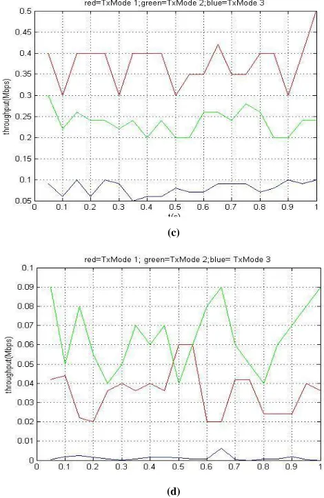
(a)
(b)
(c)
(d)
Figure 2. (a) Comparison between three transmission modes for pathloss model- Rural, UE near eNodeB. (b) Comparison between three transmission modes for pathloss model- Rural, UE far eNodeB. (c) Comparison between three transmission modes for pathloss model- Urban, UE near eNodeB.(d) Comparison between three transmission modes for pathloss model- Urban, UE far eNodeB.
[image:4.612.49.291.351.711.2]International Journal of Emerging Technology and Advanced Engineering
Website: www.ijetae.com (ISSN 2250-2459,ISO 9001:2008 Certified Journal, Volume 3, Issue 9, September 2013)
86
B. Simulation results of different Scheduling methods
[image:5.612.319.577.149.499.2]Mapping of UE and eNodeB within the Cell:
Figure 3. The comparative distance between eNodeB and UE. Red dot represents eNodeB (Center).
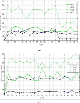
Here Solid Lines- SISO; Dot-Dash Lines- Transmit Diversity; Green- Proportional Fair; Blue- Round Robin.
(a)
(b)
(c)
(d)
Figure 4. (a) Simulation result for UE position 1, (b) Simulation result for UE position 2, (c) Simulation result for UE position 3, (d)
Simulation result for UE position 4.
[image:5.612.43.299.375.706.2]International Journal of Emerging Technology and Advanced Engineering
Website: www.ijetae.com (ISSN 2250-2459,ISO 9001:2008 Certified Journal, Volume 3, Issue 9, September 2013)
87
V. CONCLUSION
In this paper, the effect of transmission mode 1,2 and 3 in various multipath channel models is analyzed. In case of rich multipath environment like urban channel model, the transmission mode 1 should be near the vicinity of eNodeB for better performance and throughput. Transmission mode 2 become dominant as the UE moves away from eNodeB. In case of rural area and poor multipath environment, transmission mode 2 is recommended in the vicinity of base-station and eNodeB. The performance of transmission mode 3 will become dominant with the increase of distance between eNodeB and UE. For rural area, the cell size is large comparing with the urban case. LTE ensures that the users located at the edge of the cell will receive data with an increased rate, capacity & reliability [6]. To implement this Beamforming Technique is deployed and it is the best mode for users staying far from eNodeB. In this paper, the performances of round robin and proportional fair scheduling methods for two different downlink transmission modes in LTE is also analyzed. Transmit diversity gives better performance for various UE locations within the cell because of its robustness in fading scenarios. However, for different transmission modes, it is found that proportional fair gives very good data rate in most cases. Although round robin gives better individual data rate when the UE is located too far away from eNodeB, the absolute value of this data rate is not that high. Thus, the resources are not then properly utilized and so, proportional fair may still be a better choice. Round robin treats the UE with the best fairness but proportional fair can maintain a balance between fairness and throughput.
However, as the results show, the UE is able to improve SNR and make good use of resources when transmit diversity is used. The performance of cell edge users using transmit diversity manifest that the use of round robin scheduling in the cell may not lead to significant sacrifice of cell throughput if transmit diversity is used. Further research is still possible beyond the outcomes presented in this paper. It is required to define obvious threshold which will trigger the switching among various transmission modes.
REFERENCES
[1] Stefania Sesia, Issam Toufik and Matthew Baker, “LTE- the UMTS long term evolution: from theory to practice ,” 2009 John Wiley & Sons, Ltd. ISBN: 978-0-470-69716-0.
[2] LTE System Level Simulator v1.0r295 by Institute Of communication and Radio Frequency Engineering,Vienna University of Technology,Vienna.
[3] Harri Holma and Antti ToskalaI, “LTE for UMTS - OFDMA and SC-FDMA Based Radio Access,” 2009 John Wiley & Sons, Ltd. ISBN: 978-0-470-99401-6.
[4] 3GPP Technical Specification 36.213, „Evolved Universal Terrestrial Radio Access (E-UTRA); Physical Layer Procedures‟, www.3gpp.org .
[5] LTE Link Level Simulator v1.0_ r620 by Institute Of communication and Radio.
[6] Md. Tawhid Kawser, “ Easy Description of LTE Protocols.”. [7] M. Schwartz, Mobile Wireless Communications. Cambridge Univ.