© 2016, IRJET | Impact Factor value: 4.45 | ISO 9001:2008 Certified Journal
| Page 1735
“Implementation of electric driven wheel mounted vehicle steering
system using microcontrollers”
Bhadrappa.H.R
1,H.V.Govindaraju
2, Dr. P. Venkatratnam
31
6
thSem, Mtech in VLSI Design & Embedded System, VTU regional Centre, UTL Technologies, B’lore-22
2Associate Professor, Department of E&EE, Dr. Ambedkar Institute of Technology, B’lore-56
3
Professor, Department of E&CE, VTU Extension Centre, UTL Technologies Ltd, B’lore-22
---***---
Abstract
: Advanced internal combustion engine driven vehicles to utilize power steering, automatic transmission, and differentials which are being continuously improved to meet the safety, pollution norms of the day and improved passenger comfort. But by their nature, the design adds to the complexity of the mechanical design and inefficiency. The endless quest for higher fuel efficiency continues to conserve the scarce petroleum resources.In this project, an electronic steering system is proposed and implemented which converts the differential speed of the in-wheel electric motors into direction control of the vehicle path along the road. Electronic steering eliminates the transmission and its linkages between the engine and the wheels, where the torque is needed for the motion of the vehicle. This decoupling and generation of power at the point of use results in safe, pollution free, silent and efficient vehicle. The driver is not burdened on the steering of the vehicle. The mechanical, electrical and hydraulic steering systems stand eliminated and the proposed steering system is more suited for today's autonomous vehicles.
In the proposed system Pulse Width Modulator controls H-Bridge to change the supply voltage applied to In-Wheel motor
Key Words: steering, differential speed, in-wheel, H-Bridge
1. Introduction:
For a car driven by wheel mounted electric motor the speed and torque of each motor can be controlled independently. Closed loop control method has been proposed to assist the improvement of the steering system. Two dimensional characteristics of the steering system indicate the relation between the torque of individual motor and angle of the steering wheel. This data is to design the speed of the vehicle at a different condition and turning of the vehicle for different speed of the each motor. Compared with the conventional (Ackerman) steering system vehicle, the differential speed steering shows its advantage over the simple construction. Steering process normally depends on the velocity/speed
of four wheels; the mechanical differential can be removed and replaced by an electronic control system that depends on the steering wheel angle
.
With the consideration of environmental and petroleum fuel issues major driving forces are in the development of electrical energy vehicles. Electricity in one of the alternative fuel for the driving force or the vehicle system. Parallely consider the power steering used in hydraulic or an electric motor driven steering systems uses the electric power which reduces the battery efficiency and as well as backup time for the EV’s.2. Traditional Steering System
Ackerman-Jeantand [4] mode of the steering system is as shown in the Fig-1 width and length of the simulated vehicle running at speed N m/h is W and L from the centre of the body are measured. If δ is steering angle of the front wheels, according to the Ackerman-Jeantand traditional mode of steering, turning radius R can be given by R = L
tanδ
Fig-1 Ackermann-Jeantand model
3. Differential speed steering system
© 2016, IRJET | Impact Factor value: 4.45 | ISO 9001:2008 Certified Journal
| Page 1736
introduced. Differential speed Steering system betweenthe right and left wheels is utilized as a part of the development control of vehicles. With an advent from the In-Wheel motor, the same method is suitable to take a similar control for the four-wheel independent driving vehicle. The direction of the four-wheel independent driving electric vehicle is changed by increasing or decreasing the speed of wheels at different velocities. This sort of steering framework makes the vehicle hearty and basic which gives another approach to understanding the way control of electric vehicle as appeared in Fig-2
Fig-2 Ackerman & differential steering
In a new type of electric vehicle which has in wheel electric motor configuration the four wheel system by the use of the differential speed of each wheel. This type of electric vehicle employs four wheels and actually used the motor drivers traction force controlled independently. This has an advantage which reduces mechanical linkages between each motor which leads to reducing the overall weight of the machine. Therefore, the Electronic differential speed power steering system[9][11] can be designed with more compactness, and operated with high efficiency and less maintenance requirement.
In order to realize the differential speed steering a physical model for four-wheel independent electric driven vehicle is constructed. In this model, the four wheels are driven by an individual motor and keeping the same movement of the vehicle. The vehicle is moving on a ground and dependably in contact with the surface. The physical dimensions of the constructed vehicle are shown in table 2.
Test plan
Modeling of the Body Measurements of Data
Braking and Acceleration
Steering system (Electronic Differential)
Calculating the speeds of left and right wheels by sensing the steering angle
Controlling the driving torque and speed of the two pairs in-wheel traction motors
Table.2Physical Parameters of The Simulated Vehicle
Body Length L 93mm
Body Width W 170mm
Body Hight H 72mm
Radius of wheel 36mm
Weight of body 2.06kg
4. Kinematic model of vehicle Steering
Say
𝑣
Rand𝑣
Lare linear velocities with respect to ICCof the vehicle. The turning radius of the vehicle can be determined from the triangles as shown in Fig-3. The radius of the vehicle path turn can be calculated from similar triangles as shown. The speed of wheel 𝑣= 2πr T where T is the time it would take to complete one full turn around ICC. The angular velocity𝜔 = 2𝜋/𝑇 and typically has the unit radians per second.
Fig-3 Kinematic model of vehicle Steering
Combining the equations for𝑣and ω we get =2π
T = 2πr
rT =
𝑣
r and consequently ω r = 𝑣.
Note that plugging in R and
𝑣
Ofor both left and rightwheel result in the same ω, hence, the following equations can hold
ω R +W
© 2016, IRJET | Impact Factor value: 4.45 | ISO 9001:2008 Certified Journal
| Page 1737
ω R −W
2 =
𝑣
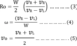
L… … … . . . (2)Where R is the distance between ICC and the midpoint of the wheel axis, and l is the length of the wheel axis Solving equations (1) and (2) for ω and R yields
Ro =
W
2
𝑣
R+
𝑣
R𝑣
R−
𝑣
L… … … … (3)
ω =
𝑣
R−
𝑣
LW … … … . . (4)
𝑣
o =𝑣
R
+
𝑣
L2 … … … . . (5)
Where ω, Ro and
𝑣
o are the yaw rate, turning radius and linear speed in the longitudinal direction of the vehicle.From the above equations (3) (4) and (5) the actual turn radius will be
Ro =W
2
ωRr (1 + λR) + ωLr(1 + λL)
ωRr 1 + λR − ωLr(1 + λL)… (6)
After considering longitudinal slip of wheels, then the actual yaw rate is given by
o =ωRr 1 + λR − ωLr(1 + λL)
W
5. Microcontroller Implementation
The small, low power loss high efficiency and high response microcontroller to drive the motors is selected arduino based ATMEG328P find suitable for this as embedded chip.
Here the project involves an Electronic steering system[11] is to remove the mechanical linkages to the steering wheel and convert to pure electronically controlled steering. Hub drive offers some useful properties and advantages of EVs over conventional vehicles like regenerative braking, being silent and pollution free. Increased Efficiency of the vehicle.
Fig-4 Block diagram of project
The hardware modules used in this project are Arduino UNO board microcontroller, DC motor drivers. Sensor unit is the main part which senses the voltage change in the potentiometer. The ATmega328P controller takes an input of sensing signal to operate DC motor driver to increase or decrease the speed of DC Motor. PWM control method of speed control of DC motor. The output of the sensor gives the information related to the speed of each motor. Percentage of PWM values are displayed on LCD unit.
L293D is a four-way high current half-driven-H driver integrated circuit. It is designed to provide bidirectional current up to 600mA and operating voltages from 4.5 V to 36 V. It is equipped with separate Input-Logic Supply Internal ESD Protection and also thermal Shutdown. This device operated to drive loads like a solenoids, relays, dc motors, stepping motor etc.
It has four driver circuits, each are enabled, when an associated enable is high. Then corresponding outputs are active. When an enable input is low, the drivers are disabled and corresponding outputs are inactive. The pair of drivers are suitable for reverse direction with proper input data.
Algorithm for steering system
Step1 look for steering angle and rotation direction
Step2 estimate the differential speed
Step3 estimate the time response for
differential speed
Step4 apply an electrical signal to the motor Repeat the above steps
6. Results and discussions
Analyzing of kinematics relation at the time of a differential speed steering system. Turning radius of the vehicle at different speed on either side is nonlinear. Here the group of values of a simulated kinematic model was tabulated in table 3.
[image:3.595.84.235.178.269.2]Fig-6 shows that the analysis carried out in matlab for turning radius of the vehicle at each step of 50 of steering angle.
Table 3 simulated test results of kinematic vehicle
Steering angle
Radius of rotation
Speed NR
Speed NL
ΔN = NR - NL
00 No RADIUS 19 19 0
STEERING SENSOR
ACCELARATION DECELARATION
SPEED SENSOR
DRIVER L293D
IN WHEEL MOTOR
AT M E G A 3 2 8 P
[image:3.595.36.260.631.751.2]© 2016, IRJET | Impact Factor value: 4.45 | ISO 9001:2008 Certified Journal
| Page 1738
50 6.27M 18.5 19.5 1
100 1.44M 18 20 2
150 0.89M 17 22 5
200 0.66M 16 24 8
250 0.45M 15 25 10
300 0.35M 12.5 27 14.5
350 0.24M 10 28 18
400 0.19M 9 29 20
450 0.12M 8.5 30 21.5
500 -- 8 31 23
550 -- 6 33 27
Fig-5 analysis of turning radius of vehicle corresponds to steering angle in simulink.
When the vehicle takes turn path, the longitudinal slip of the right and left wheels will be different. If the speed of the inner wheel is lesser than the running speed due to deceleration, or If the speed of the outer wheel is higher than the running speed due to acceleration. The longitudinal slip λ will be more than 0 in the inner wheel, and less than 0 in the outer wheel.
Assume that the two wheels on either side of the vehicle run at the same speed which is same as a vehicle. To achieve differential steering, the speed of each side of wheel changed. The turning direction of the vehicle can be determined by the side at which it has a higher speed. Let us define ΔN = NR -NL, the path of the vehicle will be left when ΔN > 0, if the path of the vehicle is right when ΔN < 0. To get required difference of speed, the idea of direction control will be implemented by following methods.
1) Speed of outer wheel is increased,
2) Decreasing the inner wheel speed, and
3) Increasing speed of outer and decreasing the speed of
inner wheels at the same time.
Fig-6 Turning radius of the vehicle corresponds to NR-NL.
Generally, for the safe view of the vehicle, the speed is necessary to be reduced or keeping in steady during the steering period. So the later two methods by reducing the speed of inner wheel will be taken into account in almost situations. Four turning path of the vehicle under different conditions are shown in Fig-7. It can be found the radius is increased corresponds to the decrease in the ΔN.
Fig-7 Turning radius of vehicle corresponding to ΔN.
7. Conclusion
Embedded controller system has been developed using ATMEGA328P and Sensors. For the demonstration purpose, a small physical model of four In-wheel independent driven electric vehicle has been constructed. In this model, the four wheels are driving by an independent In-wheel motor is controlled by small 10Kohm 10turn potentiometer as a steering wheel.
The sensor is used for controlling of four-wheel independent driven electric vehicle; hence, this method will be suitable for saving petroleum resources.
10 15 20 25 30 35 40 45 50 55
0 5 10 15 20 25
R
a
d
iu
s
o
f
v
e
h
ic
le
p
a
th
© 2016, IRJET | Impact Factor value: 4.45 | ISO 9001:2008 Certified Journal
| Page 1739
By utilizing the benefits of the independent In-wheelmotor driving electric vehicle it can replace the low efficiency (20%) diesel/petrol engine into In-Wheel electric driven wheel having an efficiency of about 80-85% With above discussions, all mechanical linkages with respect to the steering system are replaced by a lightweight electronic system.
In-wheel Electric motors are used instead of diesel or petrol engine, compared with the weight of diesel/petrol engine and four tires, the weight of the four In-wheel Electric motors are lightweight.
The fuel tank is replaced by a battery which is comparatively same weight when the tank is full.
With all the above discussions and analysis we can conclude that the in-wheel motor driven electric vehicle having less cost and more efficiency
8. Reference:
[1] Design and Implementation of an Electric Drive System for In-Wheel Motor Electric Vehicle. R.Nejat Tuncay, 1 Ozgur Ustun, 1 Murat Yilmaz, 3Can Gokce, 3Utku Karakaya. 978-1-61284-247-9/11/2011 IEEE
[2] Li Zhai, Electronic differential speed steering control for four in-wheel motors independent drive vehicle 21-, 780 – 783, 25 June 2011
[3] Danwei Wang Feng Qi, Trajectory Planning for a Four-Wheel-Steering Vehicle-IEEE, 3320 - 3325 vol.4 0-7803-6576-3 May 21-26, 2001
[4] Xiaodong Wu, Min Xu, and Lei Wang- Differential Speed Steering Control for Four-Wheel Independent Driving Electric Vehicle, 2013 IEEE international symponium 28-31 may 2013
[5] P. He1,a, Z. Dong1,b, S. Liang1, c, Z. Qi1, 2, d and H. Qiu A Novel Design of All-wheel Independent Steering Using Regenerative In-wheel motors for a Four In wheelmotor Drive Electric Vehicle Pages: 51 55 -2012, 28-30th Nov -2012, Auckland, New-Zealand [6] “Electric Power Steering with Permanent Magnet
Synchronous Motor Drive Used in Automotive Application Mr. R. G. Shriwastava,Dr.M.B.Diagavane ”978-1-61284-379-7 /11, 2011 IEEE
[7] Driving force Power Steering for the Electric Vehicles with Motorized Wheels. Li-Qiang Jin, Chuan-Xue Song,
Chang-Jian Hu. Department of Automotive
Engineering. 978-1-4244-2601-0/09/2009 IEEE [8] Modeling and Motion Stability Analysis of
Skid-Steered Mobile Robots. Hongpeng Wang, Junjie Zhang, Jingang Yi, Dezhen Song, Suhada Jayasuriya, and Jingtai Liu, 978-1-4244-2789-5 IEEE
[9] A Kind of Embedded Electric Power Steering System Based on DSP LF2407Microcontrollers for the drive train in hybrid and electric vehicles Xiong Jianqiao, Tang Xiaoqi,and Chen Jihong - white paper by texas instruments.
[10] Torque Distribution Algorithm for an Independently Driven Electric Vehicle Using a Fuzzy Control Method, Jinhyun Park 1, Houn Jeong 1, In Gyu Jang 2 and Sung-Ho Hwang 1,* Energies 2015, 8, 8537-8561; doi:10.3390/en8088537