Implementation of a Controller Unit for an Intelligent
Ventilation System (IVS) for a BTS Room
Sadeque Reza Khan
Lecturer, Dept. of EEE Prime University Dhaka, Bangladesh
Ahmed Al Mansur
Lecturer, Dept. of EEE Prime University Dhaka, Bangladesh
S.M. Ferdous
Lecturer, Dept. of EEE American International University-Bangladesh, Dhaka
ABSTRACT
Bangladesh is currently facing 1500 MW of power shortage causing serious dislocation in all spheres of life including production in fields and factories as well as in the section of cellular communication. As a result of giving support to the increasing customers the operators are improving their network by building new BTS all over the country which requires a great deal of electricity support. So to save the electricity and make the use of air conditioner less a system called Intelligent Ventilation System (IVS) is developed. An IVS is an electronic instrument that records data from the environment condition and take decision how the room temperature should be controlled. This research work deals with the design and construction of a ventilation system using the PIC16F877A which includes 10 bit Analog to Digital Converter (ADC) for data conditioning and a 256 byte EEPROM for data storing. Here we use a 4X20 line Liquid Cristal Display (LCD) for display section as well.
General Terms
ADC, Air Conditioner, BTS, Fan, LCD, Microcontroller.
Keywords
HSM20G, Intelligent Ventilation System, LM35DZ.
1.
INTRODUCTION
Bangladesh has been facing electricity shortage for many years. In last few years this problem has exceeded the common people's patient [1] . People are facing heavy load shading problem. In this hot summer people have to stay ten to twelve hours without electricity. If the authority keeps run for one hour another one hour they have to stay without electricity. One of the major steps that our Goverment has taken to solve this electricity problem is that they will not provide any power from the grid to any new BTS rooms of any Celluler operator companies like Grammen Phone, Robi, Airtel etc. They have to develop their own power station either by using generator or by developing solar plants. Now a days most of the BTS room thats the celluler operators are installing with a generator and 48 volt battery backup. So they alternate the source like they use generator for 6 hours and battery for next 6 hours to fullfil their power requrements. But it is not possible to operate an Air Conditioner (AC) by using a generator or battery for a long term. But AC is the most important part of a BTS room as the BTS room has to maintain a quite vaccum condition to keep it dust free and this creats heat like 50 to 60 degree celcius. This temperature is harmful for the equipments of a BTS room as those are very sophisticated and the room temperature must be maintained less than 40 degree celcious[2]. So to solve this problem and make the use of AC less, “ROBI” one of the leading celluler
[image:1.595.316.553.316.564.2]operator of Bangladesh has designed a system called “Intelligent Ventilation System” or IVS [3][4]. Basically, IVS is a Microcontroller based electronics device that maintains the overall environment of a BTS room by controlling a Fan unit, a Filter unit and an AC by observing the room temperature, room humidity and battery voltage level of a BTS room.
Fig 1: Total Intelligent Ventilation System Proposed by Robi
2.
PROPOSED SYSTEM
The Intelligent Ventilation System is made up of the following major components, control unit, fan unit, filter unit, and air conditioner. Figure 1 shows the proposed Intelligent Ventilation System.
2.1
Control unit
2.2
Fan Unit
This equipment does two things, first it opens a louver using a twelve volt DC motor and luvor is controlled by two limit switch. Next it runs 2 or 4 Fan according to the controlling signal coming from the controller.
2.3
Filter Unit
Filter unit also initially opens a luvor same as Fan Unit. Next it maintains dust free air circulation of the room.
2.4
Air Conditioner
It is not a real part of an IVS but it is also controlled by the IVS controller Unit. Now-a-days some sights does not contain an AC as well.
3.
HARDWARE DESIGN
3.1
Power Supply Section
[image:2.595.314.547.125.335.2]All the BTS rooms contain rectifier which provides 48 volt DC. So It is necessary to convert this 48 voilt DC to 5 volt DC which is not generally possible wihout any SMPS(Switch Mode Power Supply). So a small power supply has developed for these BTS room products, shown in fig 2. It can also be defined as a small version of SMPS [5].
Fig 2: Power Supply section of IVS
3.2
Reset Section
The most important part of this whole controller is the reset section. Because it is working as an external watchdog timer for the microcontroller.
3.3
Main Controller Section
The objective of this system design is to give the analog voltage as input, to the analog input channel of the IC. The input voltage is then converted to digital by the ADC of the PIC16F877A [6], [7]. It is also necessary to store the preset values in the EEPROM of the IC to compare it with the current data collected from ADC . The microcontroller will receive analogue voltage from its 5 A/D channel ports . The LCD is connected with one of the output port of the microcontroller. 4 setting switch is connected with 4 pins of the input port. The ports were so programmed that they scans to check if the switch was pressed or not when first time any one entering into the device and it continues this for 5 seconds then continues the main program and starts to show different ADC values and preset values in the LCD connected to the output port of the microcontroller.
3.4
Sensor Section
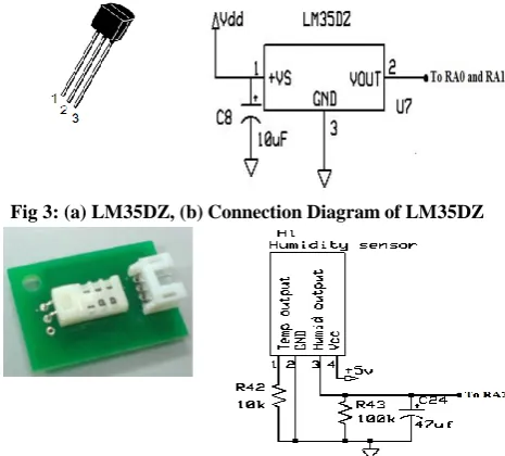
Two types of sensors are used in this circuit: 1.Two temperature sensors, 2. One humidity sensor. There are two
temperature. Humidity sensor is used to mesaure BTS room humidity. LM35DZ [8] is used as temperature sensor, shown in fig 3(a) and HSM20G [9] is used as humidity sensor, shown in fig 3(c). Both these two sensor give linear data.
Fig 3: (a) LM35DZ, (b)Connection Diagram of LM35DZ
Fig3: (c)HSM20G, (d) Connection Diagram of HSM20G
3.5
Battery Voltage Monitor System
Battery voltage level monitoring is one of the important part of this device. So it is possible to monitor the battery voltage level of a BTS room by using the given circuit, shown in fig 4 (a).
Fig 4: (a) Battery Voltage Monitoring section, (b) 5KΩ multiturn
3.6
Display Section
[image:2.595.56.285.333.464.2]We use 4X20 Line LCD(Liquid Crystal Display) in this project. LCD is now a very common choice for graphical and alphanumeric displays [10]. Figure 5 shows a 4X20 line LCD.
[image:2.595.325.552.427.512.2] [image:2.595.338.518.606.698.2]3.7
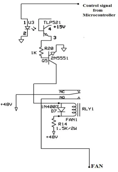
Fan Driving Section
[image:3.595.343.512.73.296.2] [image:3.595.66.268.120.414.2]This section is used to provide 48 volt DC voltage to the Fan unit of IVS. Here we design to give 48 volt individually to all 4 fans. Figure 6 shows the fan driving section.
Fig 6: Fan driving Section
3.8
AC Driving Section
[image:3.595.330.522.354.476.2]To drive AC a Solid State Relay is used which can drive upto 80 amperes of starting current. A solid state relay (SSR) is an electronic switching device in which a small control signal controls a larger load current or voltage [11]. Figure 7 shows a Solid State Relay.
Fig 7: Solid State Relay
3.9
Alarm Section
There can be three fault generated from the system. They are Fan Fault, Louver Fault and Low Battery voltage. For these three fault only one alarm that is “IVS Fault’’ must be given by the main controller to the alarm box of the BTS room through a relay contact. Figure 8 shows a alarm section.
Fig 8: Alarm Section
3.10
Motor Driving Section
[image:3.595.317.547.504.700.2]To open the hood of the louver a 12 Volt DC motor of atleast 10 RPM is used and this motor is drived by the main controller. Figure 9 shows the motor driving section.
Fig 9: Motor Driving Section
4.
OVERALL SYSTEM
[image:3.595.84.248.514.590.2]In IVS Controller the Sensors and other ADC components are connected in Port A of the Microcontroller PIC 16f877A[12], [13]. Setting switches and motor driving sections are
connected in Port B. Display and alarm sections are connected in Port C. Fan and AC driving sections are connected in Port D. Louver fault sensing section is connnected in Port E of controller IC. Figure 11 shows the overall connection diagram of IVS.
5.
RESULT
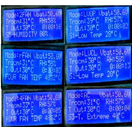
[image:4.595.313.535.72.225.2]The complete hardware of the intelligent ventilation system is shown in fig 11. The fan unit of an IVS, louver of fan and filter unit is shown in fig 12 and fig 13 respectively. Finally the different display outputs are shown in fig 14.
Fig 11: Complete Hardware of IVS Controller
[image:4.595.54.286.239.408.2]Fig 12: Fan Unit of a IVS
Fig 13: Louver of Fan and Filter Unit
[image:4.595.314.535.252.464.2] [image:4.595.55.274.466.627.2]6.
FLOW CHART
Fig 15: Conceptual logic diagram of IVS
The flow chart represents the complete logic of Intelligent Ventilation System (IVS) controller shown in fig 15. The controller responds with the change of temperature and humidity of a BTS room and it runs two fans or four fans following a louver open signal according to the logical sequence. If it fails to maintain the BTS temperature and
7.
CONCLUSION
The target of this work is to develop a ventilation system for BTS room cost efficiently and accurately. From the results of the performance study, we can say that the developed system works properly and can provide economic benefits. One target of the system is to watch the condition of a BTS room and take some decission automatically. A microcontroller chip 16F877A is used in the controller and it has a 10 bit ADC module also. So, the system can read the necessery data from the environment accurately. The LCD used in this system can display the ADC data at different environmental conditions . It also display the applied modes by the controller. The other target of the system is to provide economic benefit to its users. Cheap and available instruments are used to design the system. And it is also playing an important role to save some electricity for a country. So, it is affordable for developing country like Bangladesh. The efficiency of the system is satisfactory. The A/D converter module has a high resolution, so accuracy of the system is nearly perfect. The overall performance of the system is satisfactory and successful.
8.
REFERENCES
[1] Electricity shortage is a serious problem in Bangladesh [Online]. Available: http://www. hotneus.com
[2] MOBILECOOL/FCB, Available at:
http://www.advancedcoolingtech.com/products/FCB-EN_US.pdf
[3] Roby of Bangladesh reduces CO2 emission by 30 percent in 2010, by Michael Kuehner. http://telecomlead.com/blog-main.php?id=34&blgid=8
[4] Green Telecom, available at:
http://www.ekantipur.com/the-kathmandu-post/2011/03/26/money/green-telecom/219899.html [5] SMPS, 15 December 2011 [Online]. Available:
http://en.wikipedia.org/wiki/SMPS
[6] PIC16F87XA Data Sheet: 28/40/44-Pin Enhanced Flash Microcontrollers, © 2003, Microchip Technology Incorporated.
[7] PIC Tutorial Hardware- PIC Vietnam [Online].
Available: http://www.picvietnam.com/download /Nigel%tutorial.pdf
[8] LM35DZ Available: http://www.alldatasheet.net/ datasheet -pdf/pdf/8875/NSC/ LM35DZ.html
[9] HSM-20R Humidity Sensor Module, Available: http://www.justmystage.com/home/bellseki/HSM-20G.pdf
[10] Matrix multimedia E-Blocks, 2011 Available: http://www.matrixmultimedia.com/E-Blocks hardware .php
[11] Solid State Relay, December 2011 [Online]. Available:http://en.wikipedia.org/wiki/Solid_state_relay [12] PIC Flowcode, [Online] . Available: http://www.matrix
-multimedia.com/ flowcode3a-x.php.