Design of 1-Dimentional FIR Filter using Modified
Widrow-Hoff Neural Network
Amit Mishra
Jaypee University of Engineering and Technology Guna, Madhya Pradesh, India
Khushboo Pachauri
Jaypee University of Engineering and Technology Guna, Madhya Pradesh, India
Zaheeruddin
Jamia Millia Islamia (A Central University) New Delhi, India
ABSTRACT
This paper is intended to provide an alternative optimization ap-proach for the design of one-dimensional finite impulse response filter based on modified Widrow-Hoff neural network. This tech-nique is based on minimization of weighted square-error function in frequency domain. Design guidelines and implementation ap-proach was presented along with the proof of convergence theorem for the stability of neural network algorithm. Few examples which include single and multiband digital finite impulse response filters are presented; comparisons to existing methods are made. Compu-tational complexity of various neural-based methods are also com-pared. As simulation results illustrates, the proposed neural net-work based method is capable of achieving an excellent perfor-mance for digital filter design.
Keywords:
FIR filter, weigted square-error function, modified Widrow-Hoff neural network, convergence theorem.
1. INTRODUCTION
Linear phase finite impulse response (FIR) digital filters are fre-quently used in signal processing applications because of their generalized stability and freedom from phase distortion. The problem of designing linear phase FIR filters has been studied extensively and solved in a number of different ways [1]−[4]. Much effort has been spent on designing filter based on win-dowing methods and frequency sampling [5]. The winwin-dowing method is the earliest and simplest approach of FIR filter de-signing. In this approach, a truncated ideal low pass filter having a certain bandwidth is generated, and then a chosen window is applied to achieve certain stop band attenuation. The use of win-dows offers very little design flexibility e.g. in low pass filter de-sign, the pass band edge frequency generally cannot be specified exactly since the window smears the discontinuity in frequency. In frequency sampling method, evenly spaced samples of a de-sired frequency response are created, and the IDFT is computed to obtain an impulse response. This method is useful for the design of non-prototype filters where the desired magnitude re-sponse can take any irregular shape but has drawback i.e. the fre-quency response obtained by interpolation is equal to the desired frequency response only at the sampled points whereas at the other points, there will be a finite error present. Because both the methods can not accurately control border frequencies of pass band and stop band in the practical application and are based on
fixed formulation and not iterative, as a result, many researchers have presented some optimal design approaches.
Optimal FIR filter techniques were initiated in early 1970s. Mainly Remez Exchange Algorithm was the basis of these tech-niques and it has built for FIR filters. The algorithm proposed by Parks and McClellan [6], [7] uses the Remez Exchange method to find the optimal approximation for the magnitude response. After that, many algorithms have been developed based on Lin-ear Programming (LP) [8], [9], Quadratic Programming and Heuristic methods in Artificial Intelligence (AI) Tools, such as Neural Networks [10]−[15].
Remez Exchange Algorithm and linear Programming are opti-mum in the sense that these methods achieve both a given dis-crimination and a specified selectivity with a minimum length of the filter impulse response. Unfortunately both the schemes are computationally intensive as the filter length is increased. The weighted least-square (WLS) methods [16], [17] show much flexible utilization for any type of filter design analytically but these approaches are typically based on linear algebra methods that requires computationally intensive matrix inversion. In this paper, an efficient method based on neural networks pro-posed for the design of linear phase FIR filters. The design prob-lem was formulated based on the approximation of magnitude response using modified weighted Widrow-Hoff neural network architecture.
In Sect. 2, motivation and some properties of modified Widrow-Hoff neural network are briefly reviewed in order to perform the filter design problem along with the linear transformation abil-ity of proposed network. Then a convergence theorem and algo-rithm to implement the FIR digital filters using ANN is proposed along with a comparison of computational complexity of pro-posed method with other neural network based models in Sect. 3. In Sect. 4, the designed examples and simulated results are described to demonstrate the effectiveness of the proposed algo-rithm. Finally, the conclusions are stated in Sect. 5.
2. FILTER DESIGN USING MODIFIED WIDROW-HOFF NEURAL NETWORK (MWHNN)
The standard Widrow-Hoff neural network described as ADA-LINE (ADAptive LInear NEuron) is based on Least Mean Square (LMS) algorithm.
Table 1. The parameters of the four types of filter
Type I II III IV
s s=0 s=0 s=1 s=1
N Odd Even Odd Even
M N−1
2 N 2 N−1 2 N 2
n0 0 1 1 1
an
h(M), n= 0 2h(M−n), 1≤n≤M
2h(M−n),
1≤n≤M
2h(M−n),
1≤n≤M
2h(M−n),
1≤n≤M ϕn(ω) cos(nω) cos(n−12)ω sin(nω) sin(n−
1 2)ω
a linear transfer function, then the transformation from the input vector to the output vector is a linear transformation. This makes our proposed model suitable for filter design with the capability of linear transformation [18].
2.1 Motivation of Filter Design
The frequency response of a linear phase digital filter [5] is given as
H(ω) =
N−1
X
n=0
h(n)e−jωn=e−jωN2−1ejsπ2A(ω), (1)
whereh(n) (n = 0to N−1)is the impulse response, ωis frequency,Nis the filter length, and
s=
0, ifh(n)is symmetric
1, ifh(n)is antisymmetric
The freuency response of real-valued amplitude responseA(ω)
can be expressed as the general form,
A(ω) =
M
X
n=n0
anϕn(ω) (2)
whereanandϕn(ω)are the filter coefficient vector and appro-priate trigonometrical function respectively.
These parameters can be divided into four types of filters, ac-cording to whether the filter length is even or odd and whether the impulse response is symmetric or antisymmetric. All the re-sults are shown in Table 1. From Eq. (2),A(ω)for type I filter [5] can be expressed as
A(ω) =
M
X
n=n0
anϕn(ω) = M
X
n=n0
ancos(nω) (3)
whereM=N−1
2 andn0=0. Now, sample uniformlyA(w)in fre-quency axis to get its discrete valuesA(wl).
A(ωl) = M
X
n=0
ancos(nωl) =aΦn(ωl) (4)
whereA(ωl) is the magnitude response corresponding to the sampling point atwlandLis the number of point sampled be-tween 0 toπi.e.wl∈[0−π]. The sampling point(ωl)can be expressed asωl=Llπ, wherel= 0,1, . . . L. The trigonometric function matrixΦn(ωl)can be evaluated
as-Φn(ωl) =b=
1 cos(ω1) . . . cos(nω1)
1 cos(ω2) . . . cos(nω2) ..
. ... ... ...
1 cos(ωL) . . . cos(nωL)
(5)
Now, Eq. (4) can be written as
A(ωl) =bTa (6)
The error response is expressed as
ek=Ad−A(ωl) (7) whereAdis desired magnitude response.
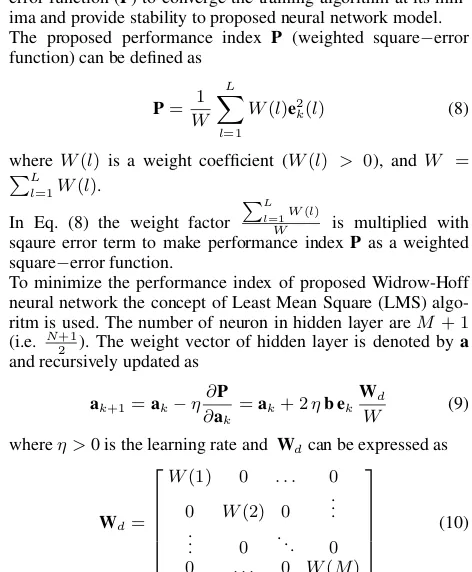
In this work, the performance index is chosen as weighted square error function (P) to converge the training algorithm at its min-ima and provide stability to proposed neural network model. The proposed performance index P (weighted square−error function) can be defined as
P= 1 W
L
X
l=1
W(l)e2k(l) (8)
whereW(l) is a weight coefficient (W(l) > 0), andW =
PL l=1W(l).
In Eq. (8) the weight factor
PL l=1W(l)
W is multiplied with sqaure error term to make performance indexPas a weighted square−error function.
To minimize the performance index of proposed Widrow-Hoff neural network the concept of Least Mean Square (LMS) algo-ritm is used. The number of neuron in hidden layer areM + 1
(i.e. N2+1). The weight vector of hidden layer is denoted bya
and recursively updated as
ak+1=ak−η
∂P ∂ak
=ak+ 2ηb ek
Wd
W (9)
whereη >0 is the learning rate and Wdcan be expressed as
Wd=
W(1) 0 . . . 0 0 W(2) 0 ...
..
. 0 . .. 0
0 . . . 0 W(M)
(10)
The termWd
W in Eq. (9) is a weight factor which depends on the selection of weight coefficient vectors using Eq. (18).
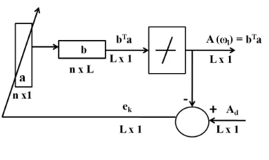
2.2 Proposed Neural Network Model
The proposed model for FIR digital filter design is shown as in Fig. 1, whereaand bare the input vector and weight matrix of the NN model respectively.A(ωl)is the amplitude response of the model andek is the error of network, whereAdrepresents the desired magnitude response. Here,Landnare the number of points sampled at frequency axis and required number of hid-den neuron in the ANN model respectively.
During training phase the errorekis evaluated as the difference of desired and current amplitude response of the neural network and using error back propagation algorithm the weights are up-dated with appropriate choice of learning rateη.
3. CONVERGENCE AND COMPUTATIONAL
COMPLEXITY ANALYSIS
[image:2.595.309.545.270.556.2]sec-Table 2. Computational complexity involved in NN based models
Operation−→ Integer Integer Sigmoid
Algorithm↓ multiplication addition function
Conventional Least−square method [16] ≈n2L – –
Bhattacharya and Antoniou method [10] 2nL(1 +n) +n(2L+ 1) 2nL(1 +n) +n(2L+ 1) n+ 2L+n(2L+ 1)
Yuo-Dar Jou method [14] n(1 +n) n(1 +n) n
Neural network optimization method [19] n(1 +n) n(1 +n) n
Proposed algorithm n(n) n(n−1) –
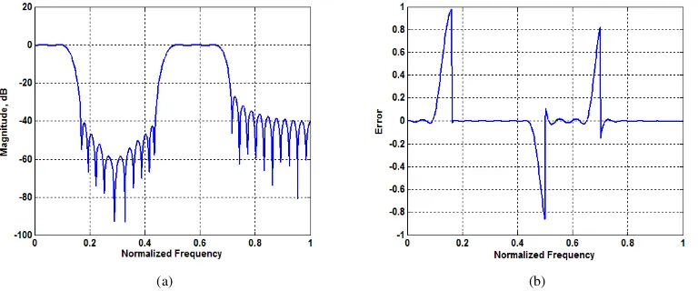
[image:3.595.96.509.105.370.2](a) (b)
Fig. 2. Design of low-pass FIR filter using modified Widrow-Hoff NN with filter lengthN=31,ωp=0.3π,ωs=0.3π, and sampling gridL=180.
(a) Amplitude response, (b) Designed error response (Normalized toπ)
Fig. 1. Proposed modified Widrow-Hoff Neural Network (MWHNN) model
tion a proof of convergence theorem is presented to show the convergence and stability of the proposed neural network algo-rithm. The computational complexity involved in various neural network based models is also discussed.
3.1 Convergence Theorem
THEOREM 1. Algorithm of the neural network is convergent, if learning rate satisfies 0< η < 2W
(N+1)W(l), whereW(l)>0, Nis odd integer,N−1is the order of FIR filter and N+12 is the number of hidden neurons used in neural network.
PROOF. Lets define performance index P as a Lyupunov function shown in Eq. (8).
Therefore,4Pcan be expressed as
4P=Pk+1−Pk=
1 W
L
X
l=1
W(l)e2k+1(l)−e 2 k(l)
, (11)
wherel=1, 2,. . . L.
The term4ek(l)can be expressed as
4ek(l) =
∂ek(l)
∂a
T
4a (12)
from Eq. (9), we get,
4a=−η 2
WW(l)ek(l) ∂ek(l)
∂a (13)
Therefore Eq. (12) can be expressed as
-4ek(l) = −η
2
WW(l)ek(l)
∂ek(l)
∂a
T
∂ek(l)
∂a
= −η 2
WW(l)ek(l)k ∂ek(l)
∂a k 2
(14)
wherek · k=P| · |2is the square of Euclidean norm. From Eq. (11)
4P = 1 W
L
X
l=1
W(l){ek(l) +4ek(l)} 2
−e2 k(l)
= 4 W2
L
X
l=1
W2(l)e2 k(l)k
∂ek(l)
∂a k 2
−η+η2 1 WW(l)k
∂ek(l)
∂a k 2
(15)
From Eq. (15), if
−η+η2 1 WW(l)k
∂ek(l)
∂a k 2
[image:3.595.63.546.410.819.2] [image:3.595.71.266.438.554.2](a) (b)
Fig. 3. Design of high-pass FIR filter using modified Widrow-Hoff NN with filter lengthN=41,ωs=0.3017π,ωp=0.3994π, and sampling grid
L=180. (a) Amplitude response, (b) Designed error response (Normalized toπ)
(a) (b)
Fig. 4. Design of multiband FIR filter using modified Widrow-Hoff NN with filter lengthN=65,ωp={0≤ω≤0.1π} ∪ {0.5π≤ω≤0.66π},
ωs={0.16π≤ω≤0.44π} ∪ {0.7π≤ω≤π}, and sampling gridL=501. (a) Amplitude response, (b) Designed error response (Normalized to
π)
the term4P≤0and algorithm is convergent. Therefore accord-ing to Eq. (4) and (7)
k∂ek(l) ∂a k
2 = k∂ek(l)
∂A(ωl)
∂A(ωl)
∂a k 2
=
M
X
i=0
|Φn(ωl)|2=
N+ 1
2 (17)
by substituting the value ofk∂ek(l) ∂a k
2from Eq. (17) to (16), we
get0< η < 2W (N+1)W(l).
The derivative of performance index4P ≤ 0, if learning rate satifies0 < η < (N+1)2WW(l), and the algorithm converges. If 4P= 0, from Eq. (13) and (15) we have4a= 0, therefore the NN model is stable and hence, theorem is proved completely.
3.2 Selection of Weight coefficient Vector
The appropriate values of weight coefficient vector improve the performance of ANN filter design therefore selection of weight vector is the key step of proposed algorithm and should be
cho-sen in the same range as shown in Eq. (18).
W(ωl) =
ωp≥1, in the pass-band
ωp edge≥1, on the pass-band edge
ωs edge≥1, on the stop-band edge
ωt= 1, in the transition-band
ωs≥1, in the stop-band
(18)
The values of weight coefficient vectors (W(ωl)) are selected more than unity to minimize the ripples present in pass band and stop band of magnitude response of filter. The transition band does not demand any ripple minimization therefore weight coefficient are kept unity in this region. The ripples are minimized during updation of weight vector (ak+1) of hidden layer of modified Widrow-Hoff Neural Network using Eq. (9).
The following algorithm summarize the proposed design of FIR filter using modified Widro-Hoff Neural Network.
<step 1>Set initial iteration numberk = 0, stop criterionε, learning rateηaccording to convergence theorem and weight coefficient vectorW(ωl)using equation Eq. (18).
<step 2>Sample the desired magnitude responseAduniformly on the frequency sample point atωl= Llπ, wherel=1,2,. . . L.
[image:4.595.104.488.325.485.2]<step 4>produce amplitude response A(ωl)of neural network. Compare it with desired responseAdand compute errorekand performance indexPusing Eq. (7) and (8).
<step 5>Update the weight vectoraof the network according to Eq. (9).
<step 6>Check the stop criterion. IfP≤ε, condition satisfied, we terminate the design process. Otherwise, setk=k+ 1and go to step 4 for the next iteration.
3.3 Computational Complexity
In Table 2, a complexity comparison of different schemes and algorithms is summarized, wheren andL are the number of neurons (filter coefficients) and number of frequency points on desired response (sampling grid) respectively.
[image:5.595.66.275.333.398.2]The neural network based models proposed by Bhattacharya [10], Yuo-Dar Jou [14] and Zhao [19] are used feedback neu-ral network, compacted feedback neuneu-ral network and continu-ous Hopfield neural network respectively. Table 2 shows that the proposed method requires a less number of computation as com-pared to other techniques.
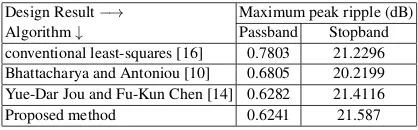
Table 3. Performance comparison for lowpass FIR filter design
[image:5.595.66.274.442.495.2]Design Result−→ Maximum peak ripple (dB) Algorithm↓ Passband Stopband conventional least-squares [16] 0.7803 21.2296 Bhattacharya and Antoniou [10] 0.6805 20.2199 Yue-Dar Jou and Fu-Kun Chen [14] 0.6282 21.4116 Proposed method 0.6241 21.587
Table 4. Performance comparison for highpass FIR filter design
Design Result−→ Maximum peak ripple (dB) Algorithm↓ Passband Stopband Parks-McClellan Transformation [6] 0.0985 37.99 Neural network optimization [19] 0.0981 38.13 Proposed method 0.0954 38.49
4. SIMULATIONS AND COMPARISONS
In this section, Matlab programs are used to design three examples of 1-Dimentional FIR digital filters, including the least-squares using the implementation of MWHNN to evaluate the performance of the proposed technique. The weight coef-ficient vector is set according to Eq. (18) so as to obtain least square approximation in each example.
Example-1. (Low-pass filter): The desired amplitude re-sponse Ad is a low-pass FIR filter with unity gain in the pass-band{0≤ω≤ωp= 0.30π}, zero gain in the stop-band {ωs= 0.30π≤ω≤π}with a sampling frequency ofπ. The filter length is chosen to beN=31 (i.e. type I filter) with sam-pling grid ofL=180 [14]. The MWHNN iterates for 1000 times to converge to a low-pass filter with learning rateη=0.1. Fig. 2 illustrates the amplitude response of the low pass FIR filter. Table 3 shows the performance comparison of the low-pass filter design with conventional least-squares [16], Bhattacharya [10], You-Dar Jou [14], and the proposed method.
Example-2.(High-pass filter): For this simulation a high-pass FIR filter with zero gain in the stop-band
{0≤ω≤ωp= 0.3017π}, unity gain in the pass-band {ωs= 0.3994π≤ω≤π}with a sampling frequency of π is selected as an example from literature [19]. The filter length is chosen to beN=41 (i.e. type I filter) with sampling grid of
L=180. The MWHNN iterates for 1000 times to converge to a high-pass filter with learning rateη=0.1. Fig. 3 illustrates the amplitude response of the low pass FIR filter. Table 4 shows the performance comparison of the high-pass filter design with H. Zhao [19], Parks-McClellan transfromation [6] and the proposed method.
Example-3.(Multiband filter): The desired amplitude response
Adis a 65−tap multiband filter with unity gain in the pass-band region ωp = {0≤ω≤0.1π} ∪ {0.5π≤ω≤0.66π}, zero gain in the stop-band regionωs = {0.16π≤ω≤0.44π} ∪ {0.7π≤ω≤π}. The filter length(N)and sampling grid(L)
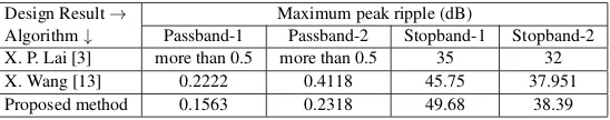
are chosen as 65 and 501 respectively [13]. The MWHNN iterates for 2000 times to converge to a multiband filter with learning rateη=0.1. Fig. 4 illustrates the amplitude response of the multiband filter. Table 5 shows the performance comparison of the multiband filter design results with X. P. lai [3], X. Wang [13] and the proposed method.
From all three examples, It is evident that the proposed network shows a better convergance to a optimal solution and it’s performance is superior to other methods.
5. CONCLUSIONS
The proposed MWHNN based approach is an alternatively com-putationally effective, weighted least square technique for de-signing FIR digital filters. Few examples are simulated and com-pared on the basis of maximum peak ripples in passband and stopband of FIR filter. Furthermore, the required number of neu-rons in MWHNN is independent of the sampling grid in the frequency domain and approximately proportional to the filter length. Therefore, higher order filter can further be designed ef-ficiently by using the proposed neural network approach.
6. REFERENCES
[1] S. Sunder, “An efficient weighted least-squares design of lin-ear phase nonrecursive filters,”IEEE Trans. Circuits Syst. II, 4th ed. vol. 42, no. 5, pp. 359–361, 1995.
[2] M. Okuda, M. Ikehara and S. Takahashi, Fast and stable least-squares approach for the design of linear phase FIR fil-ters, IEEE Signal Process. Lett., vol. 46, no. 6, pp. 1485-1493, (1998).
[3] X. P. Lai, “Constrained Chebyshev Design of FIR filters,” IEEE Trans. Circuits Syst. II, vol. 51, no. 3, pp. 143–146, 2004.
[4] S. C. Pei, and H. S. Lin, Minimum-Phase FIR filter de-sign using real cepstrum, IEEE Trans. Circuits Syst. II, Exp. Briefs, vol. 53, no. 10, pp. 1113-1117, (2006).
[5] J. G. Proakis and D. G. Manolakis,Digital Signal Process-ing, 4th ed. Pearson Prentice Hall International, Inc, 1996. [6] L. R. Rabiner, J. H. McClellan, and T. W. Parks, “FIR digital
filter design techniques using weighted Chebyshev approxi-mation,”Proc. IEEE, vol. 63, pp. 595–610, 1975.
[7] P. Zahradnik and M. Vlcek, Analytical design method for optimal equiripple comb FIR filters, IEEE Trans. Circuits Syst. II, Exp. Briefs, vol. 53, no. 2, pp. 112-115, (2005). [8] H. D. Tuan, T. T. Son, H. Tuy and T. Nguyen, “New
linear-programming-based filter design,”IEEE Trans. Circuits Syst. II, Exp. Briefs, vol. 52, no. 5, pp. 276–281, 2005.
[9] A. T. Chottera and G. A. Jullien, A linear programming approach to recursive digital filter design with linear phase, IEEE Trans. Circuits Syst., vol. 29, pp. 139-149, (1982). [10] D. Bhattacharya, and A. Antoniou, “Real time design of
Table 5. Performance comparison for multiband FIR filter design Design Result→ Maximum peak ripple (dB)
Algorithm↓ Passband-1 Passband-2 Stopband-1 Stopband-2 X. P. Lai [3] more than 0.5 more than 0.5 35 32 X. Wang [13] 0.2222 0.4118 45.75 37.951 Proposed method 0.1563 0.2318 49.68 38.39
[11] D. Bhattacharya, and A. Antoniou, Design of equiripple FIR filter using feedback neural network, IEEE Trans. Cir-cuits Syst-II, vol. 45, no. 4, pp. 527-531, (1998).
[12] Yue-Dar Jou, Least-squares design of digital differentiators using neural networks with closed-form derivations, IEEE Signal Process. Lett., vol. 12, no. 11, pp. 760-763, (2005).
[13] X. Wang, Xianzhi Meng and Yigang He, “A Novel Neural Networks-Based Approach for Designing FIR Filters,”Proc. IEEE., vol. 1, pp. 4029–4032, 2006.
[14] Yue-Dar Jou and Fu-Kun Chen, “ Least-Squares Design of FIR Filters Based on a Compacted Feedback Neural Net-work,”IEEE trans. Circuits and Systems- II, vol. 54, no. 5, pp. 427–431, 2007.
[15] S. A. Hosseini and F. Farokhi, An Optimum Design of Linear Phase FIR Filters by the Generalized
Brain-State-in-a-Box Neural Network Model, Proc. IEEE., vol. 1, pp. 253-258, (2009).
[16] W. P. Zhu, M. O. Ahmad and M. N. Swamy, “ Weighted least-square design of design of FIR filters using fast itera-tive matrix inversion algorithm,” IEEE Trans. Circuits Syst-I, vol. 49, no. 11, pp. 143–146, 2002.
[17] Y. C. Lim, J. H. Lee, C. K. Chen and R. H. Yang, A weighted least square algorithm for quasi-equiripple FIR and IIR digital filter design, IEEE Trans. Signal Process., vol. 40, no. 3, pp. 551-558, (1992).
[18] M. T. Hagan, H. B. Demuth and M. Beale,Neural Network Design, 4th ed. Cengage Learning India Pvt. ltd, 2011. [19] H. Zhao and J. Yu, “A Novel Neural Network-based