© 2018, IRJET | Impact Factor value: 7.211 | ISO 9001:2008 Certified Journal | Page 2360
Virtual Music Guide For Beginners Using MATLAB and DSP Kit
Amey B. Bhat
1, Ashish W. Lonkar
2, Ojas S. Bhargave
3, Dr. Virendra Shete
41,2,3
Students, Dept. of Electronics and Telecommunication Engg, MIT College of Engg, Pune, Maharashtra, India
4Head of the Department, Dept. of Electronics and Telecommunication Engg, MIT College of Engg, Pune,
Maharashtra, India
---***---Abstract -The paper proposes a system which aims at guidingthe music enthusiasts in learning the basics of Indian classical music through instrument playing. Generally, a physical instructor is required for teaching the instruments to a beginner; this project aims at eliminating this need and makes the process hassle free and independent of guide.The basic idea of project is that it exploits the fact that each Raag is associated with certain frequency and this frequency is processed further, to achieve the objective. It also notifies the user if he goes wrong according to the laws of Indian Classical Music in his practice sessions. The musical notes played by the user are nothing but the frequencies or the pitch to be extracted and processed. As the project involves intensive audio processing, DSP (Digital Signal Processing) Kit is used as hardware component, while for software assistance MATLAB is used.
Key Words: Raag, Frequency, Pitch detection, Audio Processing, Digital Signal Processing.
1. INTRODUCTION
Indian Classical Music is based on melody rather than harmony. The basis of melody lies in the numerous Ragas available in Indian Classical Music. It takes many years for a student of music to understand and distinguish between different Ragas. Understanding the nature of all Ragas is difficult. It requires continuous and dedicated effort for a very long period to pick up this ability. Moreover, this skill depends very much on the musical sense of a person. When a Raga is sung by a musician, it is appreciated at different levels by different listeners. Musical Sound has two identifying characteristics; loudness and pitch. Loudness is power, as it depends on the amplitude or the intensity of the corresponding wave, and is measured in decibels. The pitch of a musical sound is determined mainly by its frequency and is a measure of how "high" or "low" a tone is, and is measured in hertz (Hz). The notes of the same pitch from a Guitar, Sitar, Violin and a Flute are entirely different in quality and are instantly recognizable.
1.1 Objectives
A] We are accepting two inputs from the user:
1. Base Frequency [scale]: This is the frequency of the reference note of that particular tune. For instance, in Indian classical Music, the note ‘Sa’ will be considered as the reference note. So if the scale is ‘C#’ or ‘Kaali 1’ then ‘Sa’ is equal to the frequency of ‘C#’ or ‘Kaali 1’ which is 552.6 Hz for the fifth octave. Rests of the notes in the same tune are
then calculated according to this base reference frequency. This reference note is called as the scale of the particular tune.
2. RAAG: This is a concept in Indian Classical Music which is nothing but a defined set of musical notes which are used in that particular tune. So the RAAG is that set of musical notes or frequencies.
B] Objectives of our system:
1. Extracting the frequency from the music using signal processing with the help of DSP. This will be used for tuning purpose.
2. Determining and indicating whether the tune played by learner is correct or not according to the “RAAG” specified earlier.
1.2 Concept Of Swar And Saptak In Indian Classical Music
Indian Classical Music has seven swaras, with their identities as below:- Sa, Re, Ga, Ma, Pa, Dha, Ni. These seven swaras are further sub-divided as ‘Teevra’ and ‘Komal’. Sa and Pa are ‘AchalSwaras’, which means that they can’t be sub-divided into Teevra and Komalswaras. Thus, there are 12 swaras that include Shuddha, Teevra and Komalswaras. Now, to understand the phenomenon of ‘Saptak’, we shall use harmonium keyboard or the synthesizer as shown in Fig -1. Here, both the Swaras and Saptaks could be seen in the figure.
Fig -1: Concept of Swaras and Saptaks
2. LITERATURE SURVEY
© 2018, IRJET | Impact Factor value: 7.211 | ISO 9001:2008 Certified Journal | Page 2361 characteristics (both time domain and frequency domain).
For time domain analysis, zero crossings and autocorrelation measurements are important. The important algorithm in the time domain analysis is the Average Magnitude Difference Function (AMDF), which has low computational cost and relatively easy to implement. The algorithm implemented here, in this work, is used below in our design. Also, various algorithms were tested under noisy conditions, and the best algorithm was found out.
Sanjivani S. Bhabad, et al. [2] worked on a project which utilized various techniques on pitch detection in time domain and frequency domain. Here, algorithm for autocorrelation was discussed in detail. Secondly, the Average Magnitude Difference Function (AMDF) algorithm was implemented. As specified in this project, the advantage of using AMDF is that it requires only the subtraction of the signals. This project was based on speaker recognition and the results for pitch calculation showed that the pitch value for different user for same vowel is different.
From the book written by Rulph Chassaing and Donald Reay, [3] we studied the basic of the TMS320C6713 DSK along with its Code Composer Studio (CCS). CCS provides Integrated Development Environment (IDE), for real time digital signal processing, written in the C Language. The version of CCS provided in this book was V3.3, while in our design we have used V5.5. Installation and other external files required were also referred. The introductory part of this book gives all the details of the board with its size, processor used and explains about the AIC23 Codec. The AIC23 Codec performs the functions of Analog-to-Digital Conversion (ADC) as well as Digital-to-Analog Conversion (DAC). The next part of the book gives the details about the architecture of the TMS320C6713 DSK, giving the details about the functional block diagram of the processor. The next concept which we referred was about the DSP/BIOS and RTDX using MATLAB and C Language. DSP/BIOS (Built in Operating System), provides real time analysis and data transfer for applications running on TI DSP. There are various threads/ functions in the DSP/BIOS, which have already pre-defined priority. For instance, the Hardware Interrupts (HWIs), having the highest priorities. Real Time Data Exchange (RTDX) [4] offers developers continuous bi-directional data exchange in real time with minimal variation on the application. Also, it is easy to program on both target and host, thus making it flexible with a variety of applications. Finally, MATLAB support tools were referred from variety of examples explained in this book.
The paper published by Savitha S Upadhya, [5] described about time domain pitch detection methods using Autocorrelation and Average Magnitude Difference Function (AMDF). This paper gives detailed analyses on the computation of the Autocorrelation Function (ACF). Here, the positions of the peaks were found out and distances between the successive peaks were calculated. Also, the comparison between voices and unvoiced signals were done, and the speaker was identified. Though the recognition of the speaker
was not a part of our project, but the technique used for pitch detection was same one.
3. SYSTEM BLOCK DIAGRAM AND THE COMPONENTS
Here, we are going to use Digital Signal Processing Kit i.e., TMS320C6713. The input will be taken through Lavalier Microphone and will be given to this kit. The audio signal received will be processed by this processor, and the results will be displayed on the PC terminal. The DSP Kit will require a power supply of +5 Volts. This could be seen in Fig -2.
Fig -2: Hardware block diagram of proposed system
3.1 Components
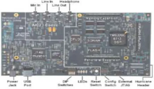
1. TMS320C6713 (DSP): The C6713 DSK, as shown in Fig - 3, is a low-cost standalone development platform that enables users to evaluate and develop applications for the TI C67xx DSP family. The DSK also serves as a hardware reference design for the TMS320C6713 DSP. Schematics, logic equations and application notes are available to ease hardware development and reduce time to market. The specifications could be seen from its datasheet. [6]
Fig -3: Board diagram of TMS320C6713 DSK
[image:2.595.321.545.216.383.2] [image:2.595.310.566.544.692.2]© 2018, IRJET | Impact Factor value: 7.211 | ISO 9001:2008 Certified Journal | Page 2362 using a microphone. A lavalier microphone, as shown in Fig
-4, (also known as a lav, body mic, collar mic, neck mic) is a small electret or Ribbon diaphragm used for television, theatre, and public speaking applications in order to allow for hands-free operation. They are most commonly provided with small clips for attaching to collars, ties, or other clothing. The term referred to any small microphone that could be hooked into the buttonhole of the lapel of a coat. The lapel microphone offered freedom of movement. Its specifications are given in Table-1.
Fig -4: Lavalier Microphone
Sr.
No. Parameter Values
1. Brand Any
2. Type Wired In-Ear
3. Audio Jack 3.5 mm 4. Frequency
Response 20 - 20000 Hz ± 3 dB 5. Sensitivity 92 – 110 dB
6. Power Handling &
Impedance 32Ω : 100mW peak / 050mW rated 16Ω : 200mW peak / 100mW rated
7. Driver Types Dual (Bass & Mid + High) 8. Sound Pressure
Level (SPL) 85-120 dB SPL/mW 9. Total Harmonic
Distortion (THD) < 1%
Table -1: Generic Earphone Specifications
3.2 Software
1. MATLAB R2014b: MATLAB (matrix laboratory) is a multi-paradigm numerical computing environment. A proprietary programming language developed by Math Works, MATLAB allows matrix manipulations, plotting of functions and data, implementation of algorithms, creation of user interfaces, and interfacing with programs written in other languages, including C, C++, C#, Java, Fortran and Python. MATLAB R2014b introduces a new MATLAB graphics system. New default colors, fonts, and styles make your data easier to interpret.
2. CODE COMPOSER STUDIO - INTEGRATED DEVELOPMENT ENVIRONMENT: Code Composer Studio is an integrated development environment (IDE) that supports TI's Microcontroller and Embedded Processors portfolio. Code Composer Studio comprises a suite of tools used to develop and debug embedded applications. It includes an optimizing C/C++ compiler, source code editor, project build environment, debugger, profiler, and many other features. The intuitive IDE provides a single user interface taking you through each step of the application development flow. Code Composer Studio combines the advantages of the Eclipse software framework with advanced embedded debug capabilities from TI resulting in a compelling feature-rich development environment for embedded developers.
4. BLOCK DIAGRAM
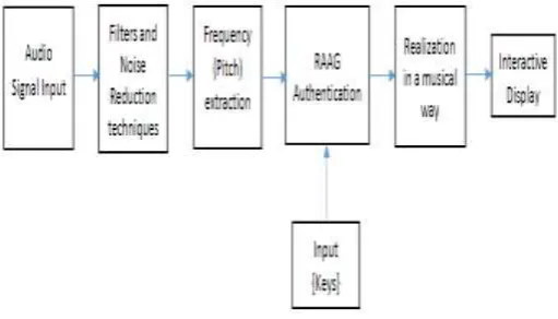
The following block diagram Fig -5, gives us the whole flow of our system. In other words it is the step by step working and analysis of our design. The major blocks would include Audio signal, Frequency extraction, Raag authentication and at the end the displaying content in the form of musical notes.
Fig -5: Block diagram / Flow of proposed system
The input sound is taken through the ‘Audio Signal Input’, which is nothing but the microphone in our design.
This output is then given to the ‘Filter and Noise Reduction Block’, which consists of ‘Low Pass Filter’, in order to remove noise and other disturbances.
The ‘Frequency (Pitch) extraction’ block is used to take out the frequencies from the clean audio signal (sound).
The ‘RAAG Authenticator’ would consist of laws and regulations of Indian Classical Music. A database of music would be stored in this block, and would compare with the music and thereby indicating whether it is correct or not.
[image:3.595.40.285.320.592.2] [image:3.595.308.564.369.515.2]© 2018, IRJET | Impact Factor value: 7.211 | ISO 9001:2008 Certified Journal | Page 2363 type of ‘RAAG’ which we will select after recording and
then compare.
The block ‘Realization in a musical way’ is used, as we have to display the Sur/Notes (Sa, Re, Ga, etc) rather than the musical frequency. This objective would be achieved by coding. For instance, if the tune played is at 440Hz, rather than displaying 440Hz, we would display ‘Sa’ on our device.
These Sur/Notes will be then displayed on the PC Terminal and it will also indicate whether the tune played is correct or not.
5. ALGORITHMS USED
The various pitch detection methods are:
Existing pitch detection methods can be divided into three groups:
The first primarily uses the time-domain characteristics.
The second uses the properties of frequency domain.
The hybrid methods combine properties of both time- and frequency-domain characteristics.
Time-domain methods are performed directly on the speech signal. For this type of pitch detectors peaks, valleys, frequency of zero-crossings, and autocorrelation measurements are very important. Time-domain measurements will provide a good evaluation of fundamental frequency if a quasi-periodic signal is appropriately processed to minimize the effects of the formant structure. Difficulties of time-domain methods for the male voice with low-pitch tone occur due to the analysis of fixed length frames at 30–40 milliseconds which, as a rule, is not suitable for fundamental frequency evaluation.
Frequency-domain pitch detectors use the property that if the signal is periodic in the time domain, then the frequency spectrum of the signal will consist of a series of impulses at the fundamental frequency and its harmonics. Such methods include Harmonic Product Spectrum (HPS), cepstrum pitch determination, and Linear Predictive Coding (LPC).
5.1 Autocorrelation:
Related to the time domain feature detector is the autocorrelation method. The autocorrelation of the signal is first formed:
And for discrete signals:
The main peak in the autocorrelation function is at the zero lag location (m = 0). The location of the next peak gives an estimate of the period, and the height gives an indication of the periodicity of the signal. The method usually requires a number of periods of data to form a reliable estimate, and thus some averaging of the frequency signal is unavoidable. The method often exhibit difficulty in detecting the period of a periodic signal which is missing the fundamental harmonic in the harmonic series. Periodic but pathological signals can be devised to cause nearly any pitch detection algorithm to fail.
5.2 Average Magnitude Difference Function (AMDF):
The pitch detector/tracker is a refinement of the Average Magnitude Difference Function (AMDF) detectors, the earliest of which is that of Miller and Weibel. Methods of this type have also been called comb-filter methods. The AMDF pitch detector forms a function which is the compliment of the autocorrelation function, in that it measures the difference between the waveform and a lagged version of itself.
The generalized AMDF function is:
and fundamental frequency is the smallest period value taken as:
For discrete signals AMDF function is given by:
© 2018, IRJET | Impact Factor value: 7.211 | ISO 9001:2008 Certified Journal | Page 2364 the issues of finite sampling rate, noise, and signal
stationary. If the signal is truly periodic with period Tu, and Tu is an integer multiple of the sampling period Ts, then all nulls at integer multiples of Tu are identically zero. If the period is not an integer multiple of Ts, however, the first null (m<>0) actually exists between two values of m. A coarse estimate of pitch is tolerable for many speech applications, but is not acceptable for analysis and synthesis of music. Compared to the small computational burden of computing the AMDF, there is no economical method of accurately interpolating between samples to find the true period. This implies that the sampling rate must be sufficiently high to yield the high accuracy required for musical applications. If the signal is quasi-periodic (amplitude modulated, corrupted by noise, etc.), the nulls will never be zero, even if Tu is an integer multiple of Ts. The problem of interpolation between lag samples to obtain an accurate pitch estimate is even further complicated in the case of a frequency modulated signal.
6. IMPLEMENTATION AND RESULTS
6.1 MATLAB
Here, in MATLAB, we have implemented the whole system, with various objectives resolved step by step. The first step taken here was the node detection along with the tuning of the instrument. The outputs are shown under the topic of results. Under the note detection the algorithm of AMDF was implemented. Also the pitches of various notes were plotted using MATLAB Function. Result using the autocorrelation function was also successfully displayed in MATLAB. Secondly, Raag detection was also done and errors were found out if any. The following objectives were carried out in MATLAB:
Objective 1: Note detection and the tuning of the instrument
Fig -6: Note and Pitch Detection
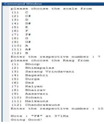
Objective 2: Error detection with respect to notes as well as the Raag specified
Fig -7-(i): Raag Specification and Error Detection
[image:5.595.325.540.76.332.2] [image:5.595.62.255.518.654.2]© 2018, IRJET | Impact Factor value: 7.211 | ISO 9001:2008 Certified Journal | Page 2365 6.2 HARDWARE
The Hardware implementation of the system could be seen below from Fig -8.
Fig -8: Hardware Setup
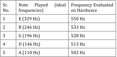
The results obtained on hardware are tabulated below. Various notes were played and their frequencies were obtained as shown in Table-2 below.
Sr.
No. Note frequencies) Played (ideal Frequency Evaluated on Hardware
1 E (329 Hz) 550 Hz
2 B (246 Hz) 533 Hz
3 G (196 Hz) 528 Hz
4 D (146 Hz) 513 Hz
[image:6.595.40.285.137.318.2]5 A (110 Hz) 502 Hz
Table -2: Result Table
Here, it could be seen that the accuracy could not be achieved. There could be various reasons for this such as discrepancies in the algorithms, external noise in the environment. We are working towards minimizing the errors and increasing the accuracy.
7. CONCLUSION
The methodology used in this design is helpful and successful. Creating the algorithm in a MATLAB .m file was instrumental in verifying the outputs over the hardware. The Note and Pitch Detection (Frequency Extraction), Raag Identification along with error correction was successfully implemented in MATLAB.
The system was implemented in real time on hardware with the DSK6713 kit and the results were obtained. The note detection part was successfully implemented on hardware
but the Raag identification still remains to be implemented from the hardware point of view.
8. FUTURE SCOPE
The future applications and extensions of this work are numerous and varied in nature.
To extend the work of this design, advanced techniques related to the full audio spectrum of the input audio sample could be created. It would be interesting to note and modify the entire spectrum of the audio sample (i.e. make a violin sound like a trumpet) rather than focus on one single frequency.
The accuracy of the proposed system could be improved by making the algorithm more versatile and robust for real time applications. Also the DSP kit used is fairly old technology (15 years!!!) and the support for this by Texas, Windows and MATLAB has gradually ceased, hence some latest kit having support and compatibility with latest software could be used.
REFERENCES
[1] Lyudmila Sukhostat, Yadigar Imamverdiyev, “A
comparative analysis of pitch detection methods under the influence of different noise conditions,” Journal of Voice, Elsevier, Volume 29, Issue 4, July 2015, Pages 410-417.
[2] Sanjivani S. Bhabad et al, “Pitch detection in time,
frequency and cepstral domain for articulatory handicapped people,” Innovation and Technology in Education (MITE), 2013 IEEE International Conference in MOOC, 20-22 Dec. 2013, Jaipur, India.
[3] Rulph Chassaing and Donald Reay, Digital Signal
Processing and Applications with TMS320C6713 and TMS320C6416 DSK, Second Edition, John Wiley and Sons, Inc. Publication.
[4] Deborah Keil, Real-Time Data Exchange WHITE PAPER,
Texas Instruments, February 1998.
[5] Savitha S Upadhya, “Pitch detection in time and
frequency domain,”2012 International Conference on Communication, Information & Computing Technology (ICCICT), Oct. 19-20, Mumbai, India, July 2012.
[6] TMS320C6713 Datasheet.
[image:6.595.37.288.394.517.2]