Energy Efficient Traffic Aware MAC Protocols for
Delay-Sensitive Wireless Sensor networks
Mayank Awasthi
ECE Department, IET, Mangalayatan University
Swati Sharma
ECE Department, IET, Mangalayatan University
ABSTRACT
Wireless sensor network (WSN) consists of large number of distributed sensor nodes, which are generally battery-powered and may not recharge easily. Consequently, how to maximize the lifetime of the nodes is an important issue while designing a MAC protocol. However, lowering the energy consumption may result in higher latency. To address such a tradeoff, this paper proposes DDC-MAC and UDDC-MAC. For delay-sensitive WSNs, DDC-MAC minimizes latency with energy consumption at a reasonable level. In DDC-MAC, each sensor node chooses a duty cycle according to traffic and average latency experienced by that node. Each node follows multiple listen and sleep schedules. Therefore, they switch into the listen state frequently and reduce the network lifetime. To minimize energy consumption due to multiple listen and sleep schedules, UDDC-MAC is proposed in which Schedule Unifying Algorithm (SUA) is integrated with DDC-MAC so that multiple listen and sleep schedules are unified into a single unified sub-optimal schedule. We study the proposed protocols by simulating these protocols using NS-2 and compare their performance with DMAC, MAC (Full), S-MAC (10%) in terms of average energy consumption of a node and average end to end latency experienced by the packet. The simulation results show that UDDC-MAC achieves improved latency performance and is more energy efficient than DDC-MAC, S-MAC and DS-MAC.
Keywords
Wireless Sensor Networks (WSNs); Dynamic Duty Cycle MAC (DDC-MAC); Unified Dynamic Duty Cycle MAC (UDDC-MAC); Schedule Unifying Algorithm (SUA); Medium Access Control (MAC); Delay Reduction.
1.
INTRODUCTION
Wireless sensor networking is an emerging technology that has a wide range of potential applications [1-2] including environment monitoring, smart spaces, health monitoring and industrial monitoring. These networks consist of a large number of distributed nodes that organize themselves into a multi-hop wireless network. Each node has one or more sensors, embedded processors and low-power radios, and is normally battery operated. These networks have severe resource constrains and energy conservation is very essential. In WSNs, energy consumption is dominated by communication module i.e. node’s radio consume most of the energy. A MAC protocol directly controls the communication module, so MAC protocol has important effect on node’s energy consumption. Therefore, to design a good MAC protocol for the wireless sensor networks we must focus primarily on energy conservation. However, lowering the energy consumption may result in higher latency. To address such a tradeoff, there is need to design a MAC protocol
having good latency performance with the energy consumption at a reasonable level.
S-MAC [3] is specifically designed to reduce energy wastage on IEEE 802.11 based sensor nodes. It uses the following mechanisms to reduce the energy consumption:
• Periodic Listen and Sleep: In wireless sensor network applications, nodes are in idle for a long time if no sensing event happens. If sensors stay in an inactive state for a long duration listening for potential communications, energy will be unnecessarily wasted under such circumstances. SMAC divides time into frames and each frame into two periods: listen and sleep. Fig. 1 illustrates the frame structure. The duty cycle is defined as the ratio of the listen interval to the frame length. The listen interval is further divided into smaller intervals dedicated to SYNC, RTS and CTS packets.
Fig 1: Periodic listen and sleep
• Collision Avoidance: Carrier sensing and RTS/CTS handshaking schemes were adopted in SMAC to solve the hidden terminal problem for data packets transmissions.
• Maintaining Synchronization: Each sensor maintains a schedule table, which is composed of neighbor schedules. SYNC packets are periodically broadcasted to maintain synchronization among the neighboring nodes. Upon the reception of an SYNC packet from its neighbor, the sensor will update the relevant entry in the schedule table such that the two nodes are synchronized. SYNC packets do not involve handshaking signaling. Synchronization has been a key requirement for all sensor networks where coordinated sleep schemes are adopted.
• Schedule Determination: A schedule is a value indicating the time left from now before switching to the sleep state, based on a local clock. There is an initialization phase for sensors to either decide its own schedule, or simply follow the clock of one of its neighbors. The latter is preferred as the cost of maintaining clocks will be reduced.
• Overhearing Avoidance: S-MAC tries to avoid overhearing by letting interfering nodes go to sleep after they hear an RTS or CTS packet. Since DATA packets are normally much longer than control packets, the approach prevents neighboring nodes from overhearing long DATA packets and the following ACKs.
Listen
Listen
39 However, S-MAC still has its own problems. For example, the
fixed duty cycle design in SMAC trades off latency for saving the energy consumption. It is efficient for energy utilization, but not suitable for delay-sensitive sensor applications such as medical, battlefields, disaster relief. Addressing on the above problem of S-MAC, DS-MAC [4] is designed which tunes the duty cycle to the node according to delay and the emptiness of packet queue. DS-MAC takes delay into consideration but duty cycle adjustment is not optimal and also in low traffic scenario its performance is same as S-MAC. Similar to DS-MAC, we propose DDC-MAC which adjusts the duty cycle of a node dynamically based on traffic and delay experienced at that node. The simulation results show that DDC-MAC achieves improved latency performance and is more energy efficient than DS-MAC
In DS-MAC and DDC-MAC each sensor node follows multiple listen and sleep schedules. Therefore they switch into the listen state frequently and reduce the network lifetime. With eventual death of such nodes cease communication between neighboring nodes. Therefore, after some time, a sensor network covering a wide area and consisting of tens of thousands of sensor nodes is divided into several isolated virtual clusters due to the death of these nodes. To minimize energy consumption due to multiple listen and sleep schedules, UDDC-MAC is proposed in which Schedule Unifying Algorithm (SUA) [5] is integrated with DDC-MAC so that multiple listen and sleep schedules into a single unified sub-optimal schedule. The convergence time analysis for SUA is discussed in [5] and it is shown to be proportional to order
of where N is total number of nodes in the network. So, SUA has acceptable scalability to the network size.
The rest of this paper is organized as follows. In Section 2 we discuss the related works. In section 3 we discuss DDC-MAC. In section 4 we discuss UDDC-MAC. Section 5 presents the simulation results to show the performance of our proposed schemes. Section 6 concludes this paper.
2.
RELATED WORKS
MAC design for wireless sensor networks can be broadly divided into schedule-based and contention based protocols [6]. The scheduling-based technique offers collision-free scheme by assigning unique time slot to each node to send or receive data. The first advantage of this is that interference between adjacent wireless links can be avoided. Thus, the energy waste coming from packet collisions is diminished. Secondly, it can solve the hidden terminal problem without extra message overhead because neighboring nodes transmit at different time slots. However, there are still lots of drawbacks. The scalability of schedule-based MAC protocols is poor since the number of time slots are fixed. Furthermore, schedule-based MAC protocols need strict time synchronization, which results in high cost on hardware and high latency for data transmission. So, these types of protocols are not suitable for WSNs. Main schedule-based MAC protocols include SSMAC (Sampling and Scheduling based MAC) [6], μ-MAC (Energy-efficient MAC) [7], DEE-MAC (Dynamic Energy Efficient DEE-MAC) [8], SPARE DEE-MAC (Slot Periodic Assignment for REception MAC) [9], and Adaptive TDMA- Based MAC [10]. In these protocols, authors didn’t consider delay, so these protocols are not suitable for delay sensitive applications.
Contention-based MAC protocols, which are mainly based on the Carrier Sense Multiple Access (CSMA) or Carrier Sense Multiple Access/Collision Avoidance (CSMA/CA), require no coordination among the nodes accessing the channel. Nodes
are allowed to independently access the medium. The core idea is that when a node needs to send data it will compete for the wireless channel. Colliding nodes will back off for a random duration of time before attempting to access the channel again. Contention-based MAC protocols have good scalability and support node changes. However, the energy efficiency of contention-based MAC protocols is still low due to collisions, idle listening, and excessive inevitable control overhead. These protocols adopt different mechanisms to reduce energy waste. So, these types of protocols are suitable for WSNs. The typical contention-based MAC protocols are S-MAC (Sensor-MAC) , DS-MAC (Dynamic S-MAC), T-MAC (Timeout-T-MAC) [11], ADV-T-MAC (ADVertisement) [12], TRAW-MAC (TRaffic AWare MAC) [13], C-MAC (Congestion aware MAC) [14], LD-MAC (Low Delay MAC) [15], TAS-MAC (Traffic Adaptive Sleep MAC) [16], ES-MAC (Enhanced S-ES-MAC) [17], DW-ES-MAC (Demand Wakeup MAC) [18], AEE-MAC (Adaptive Energy Efficient MAC) [19], and U-MAC [20]. In some of these protocols, authors had considered delay but in high traffic scenario, the delay performance of these protocols is very bad. So these protocols are not suitable for high traffic delay sensitive applications.
3.
DDC-MAC
As discussed earlier S-MAC improves the energy consumption of traditional IEEE 802.11; however, several problems arise from the adoption of S-MAC [20].
1) Fixed duty cycle: In a typical sensor network, each node has different transmission behavior and traffic load. In S-MAC, a fixed duty cycle is assigned to each node. This uniform duty cycle approach may result in energy wastage on nodes with low traffic load, and long queuing delay on nodes with heavy traffic.
2) Latency: Some sensor applications, such as medical, battlefields, disaster relief, require sensing data being sent from source to sink within a certain period. Due to fixed duty cycle assignment in S-MAC, a node cannot forward a packet until the packet’s receiver wakes up. Such latency is called sleep delay. To fulfill the delay constraint of such applications, MAC protocol must be designed under the consideration of latency.
Addressing on the above problems of S-MAC, we propose DDC-MAC protocol based on S-MAC. Our proposed scheme does not assign the same duty cycle for nodes i.e. each node is assigned a different duty cycle. Each node calculates the traffic and average delay it has experienced, and depending on these calculated values, it adjusts the periodic listen and sleep schedule. We have proposed an algorithm to adjust the duty cycle which is described in Fig. 4.
3.1. Synchronization Mechanism used in
DDC-MAC
node starts its periodic listen and sleep, it has to choose a schedule and exchange it with its neighbors. Each node maintains a schedule table that stores the schedules of all its known neighbors. The following steps are used to select a schedule and to establish a schedule table:
a) When a new node joins the network, it first listens for a fixed period (normally a synchronization period)
If it does not hear any schedules from another node, it randomly chooses its own schedule, announces its schedule by broadcasting SYNC packet and becomes a synchronizer.
If a node receives a schedule from a neighboring node before choosing its own schedule, it follows that schedule and becomes a follower.
b) When a node receives a different schedule after it selects and broadcasts its own schedule, it has two choices
If it does not have any neighboring node with different schedule, it discards its old schedule and follows the new schedule from the neighboring node.
If it has one or more neighboring nodes with different schedules, it adopts all schedules.
This scheme requires periodic synchronization among neighboring nodes to remedy their clock drift. There are two techniques are used to make it robust to synchronization errors. First, all timestamps that are exchanged are relative rather than absolute. Second, the listen period is significantly longer than clock error or drift. For example, the listen duration of 0.5s is more than 105 times longer than typical clock drift rates. Compared with schedule-based schemes with very short time slots, our scheme requires much looser synchronization among neighboring nodes. All nodes are free to choose their own listen/sleep schedules.
3.2.
Algorithm Description of DDC-MAC
In WSNs each node has a different traffic load according to its task and its location. To reflect this different traffic load, we adopted the utilization of each node as the evaluation metric U. Each node in WSNs experienced a sleep delay due to assignment of duty cycle. To reflect this sleep delay, we adopted another evaluation metric as D. As shown in algorithm Fig. 4, each node calculates the utilization U as , where the Trx denotes total receiving time, Ttx denotes total transmitting time, and Tidle denotes total idle listening time during the synchronization interval. The total idle listening time is the time that a node stays in listening mode without involving in any transmission process.
To calculate D, sending node calculates the suffered delay d during the current transmission, and attaches d in the following data packet. The delay d denotes the time elapsed between receiving the packet from upper layer and sending out RTS. This value is put into the delay field of the packet header by sending node as in Fig. 3 and retrieved by receiving node. The receiving node extracts d from each data packet and adds it. Then each node calculates the average delay D by
, where dn denotes delay of the nth packet, n denotes the number of packets received in synchronization interval. . In our proposed scheme, we define Dmax as the maximum tolerable delay, Uhigh as the threshold of high
traffic load, Dmin as the minimum tolerable delay and Ulow as the threshold of low traffic load.
[image:3.595.314.544.113.177.2]Node ID Updated Duty Cycle Information
Fig 2: SYNC Packet Format
Delay Information (dn ) nth Data Packet
Fig 3: Modified nth Datapacket
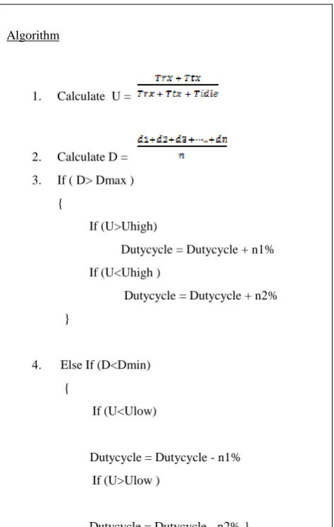
All sensors adopt a common basic service duty cycle at the beginning. A receiver sensor node checks whether the average delay experienced by it is intolerable or not. If it is intolerable, measure the utilization of a node, if the utilization U of a node is high indicating that traffic load is too heavy for the current listening schedule to afford delay. Therefore, the duty cycle will be increased by n1% to meet the requirement of such heavy traffic load and tolerable delay and this updated duty cycle is put into the SYNC packet. If the delay is intolerable and the utilization of a node is low, the traffic load is too low for current listening schedule; in that case the duty cycle will be increased by n2% to meet the requirement of tolerable delay only. The value of n1 > n2 since n1 is taking the U, D both into account and n2 is taking only D into account. Similarly if the average delay is tolerable and utilization of a node is low the duty cycle will be decreased by n1%. If the average delay is tolerable and utilization of a node is high the duty cycle will be decreased by n2%.
Algorithm
1. Calculate U =
2. Calculate D =
3. If ( D> Dmax )
{
If (U>Uhigh)
Dutycycle = Dutycycle + n1%
If (U<Uhigh )
Dutycycle = Dutycycle + n2%
}
4. Else If (D<Dmin)
{
If (U<Ulow)
Dutycycle = Dutycycle - n1%
If (U>Ulow )
[image:3.595.311.548.372.745.2]
41
5. Else
Do not update the dutycycle.
6. After choosing the duty cycle from above steps put new duty cycle in the SYNC Packet.
Fig 4: Proposed Algorithm
The protocol overhead introduced by DDC-MAC contains a “delay” field for data packets as shown in Fig. 3. The delay field in the data packet is of order of 2-4 bytes and data packet is of order of 512- 1024 bytes i.e. delay field size is very small as compared to data packet size, so the overhead due to this extra delay field can be neglected. The processing overhead due to introduction of utilization metric is also negligible. To calculate the utilization parameter we have introduced timer which monitors the state of node whether it is transmitting, receiving or idle continuously. This timer consumes a portion of energy which is equivalent to energy consumption in sleeping state of a particular node. To take this energy consumption into account we have consider that energy consumption during sleeping time in this case is twice that of previous case i.e. DS-MAC case.
4.
UDDC-MAC
In the DDC-MAC protocol, neighboring nodes send SYNC packets periodically to update the schedule followed by each other to prevent a long time clock drift. The original SYNC packet contains the node ID of the sender node and the next sleep time of this node. The next sleep time is relative to the moment that the sender node starts transmitting the SYNC packet.
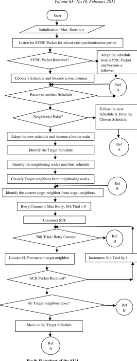
[image:4.595.311.585.64.508.2]To integrate SUA [5] in the DDC-MAC protocol, an additional field called Synchronizer ID is inserted in the SYNC packet. The synchronizer ID contains the node ID of the synchronizer of the virtual cluster (set of nodes following same schedule) and identifies the schedule followed in the virtual cluster. Both structures of original and modified SYNC packets are shown in Fig. 6 and Fig. 7. SUA integrated in the DDC-MAC i.e. UDDC-MAC protocol identifies the multiple schedules followed by a node and triggers a procedure to unify the schedules. SUA chooses the schedule with the highest synchronizer ID in the schedule table and designates it as the target schedule to move in. The target schedule is that schedule that is followed by maximum number of nodes in the network. The border node (node following multiple schedules) acquires the information of its neighboring nodes and their identification after choosing the target schedule. There is a neighbor table in which neighboring nodes information is stored and maintained. Based on the target schedule and neighboring nodes information, SUA marks some neighboring nodes as target neighbors (neighboring node that is following a schedule other than the target schedule). When target schedule is moved in, it might change the membership of a border node to another virtual cluster. So, before moving to the target schedule, the border node sends a Schedule Unifying Packet (SUP) to all target neighbors.
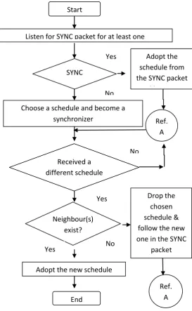
Fig 5: Flow diagram of maintaining synchronization
SUP is a data packet that contains information about the target schedule to inform target neighbors of the adoption of the target schedule by the border node. SUP is transmitted by unicasting using ACK/NACK mechanism. Instead of broadcasting, the unicasting is used to ensure the reception of SUP at all target neighbors. When all target neighbors are informed successfully about the schedule change, the current border node moves into the target schedule and becomes a non-border node. This method to adopt the target schedule repeats for all border nodes and, finally, the entire network converges to a sub-optimal schedule with the highest synchronizer ID. The flowchart of SUA is shown in Fig. 9.
Node ID Relative Next Sleep Time
Fig 6: Structure of original SYNC packet
Node ID Synchronizer ID Relative Next Sleep Time
Fig 7: Structure of modified SYNC packet
Start
Listen for SYNC packet for at least one
synchronization period
SYNC
packet
received?
Adopt the
schedule from
the SYNC packet
and become a
follower
Choose a schedule and become a
synchronizer
Ref.
A
Received a
different schedule
in normal state or
during
PND?Neighbour(s)
exist?
Adopt the new schedule
Drop the
chosen
schedule &
follow the new
one in the SYNC
packet
Ref.
A
End
Yes
No
No
Yes
5.
SIMULATION RESULTS
The simulations in our experiment are done on ns-2(ns- 2.29) network simulator. We compared UDDC-MAC with DSMAC, S-MAC (full), S-MAC (10%), and DDC-MAC. The topology used to evaluate our proposed scheme is shown in Fig. 8, where node 0 is the data source node and packets are forwarded to data sink node 4.
Fig 8: Topology used in experiment
Traffic pattern: Packets are sent from node 0 to node 4. Packet size is fixed to 512 Bytes. We attach a UDP (User Datagram Packet) agent and a CBR (Constant Bit Rate) traffic source to the source node (UDP agent is a better choice than TCP (Transmission Control Protocol) agent, because UDP is quite simple and connectionless. The traffic source is turned on after 50 seconds and keeps generating until the end of the simulation. We vary the traffic load by changing the packet inter-arrival time on the source node. For all UDDC-MAC, DDC-MAC, DSMAC and SMAC, RTS/CTS handshaking mechanisms have been assumed. For DSMAC, Dmin is set to be 1 second and Dmax is set to be 2 second. For DDC-MAC Umax is set to be .3, Umin is set to be .15, n1 is set to be 4% and n2 is set to be 2%; Dmax and Dmin are same as DSMAC.
All nodes are initialized as 10% duty average energy consumption of a node and end-to-end latency under different packet inter-arrival period cycle. To show the performance of DDC-MAC, we evaluate. The general simulation parameters are given in Table I. The simulation results of the chain topology are shown in Fig. 8, Fig. 9 and Fig. 10. The network is simulated with different loads. Source node generates the CBR (Constant Bit Rate) Traffic and transmits this to its neighbor.
Fig. 10 shows the average latency measured at the destination sensor node. The latency of SMAC (10%) is much higher than SMAC (FULL) which always utilizes the full system capacity. DDC-MAC achieves a tradeoff between these two extremes. As shown in the Fig. 8, DDC-MAC significantly reduces latency by 85% from SMAC (10%) when inter-arrival period is set to .6 sec which is more or less same as DSMAC. DSMAC can only improve latency when traffic load is high, the latencies cannot benefit from DSMAC when traffic load is light, like the cases with inter-arrival periods more than 2 secs, DSMAC degenerate itself to SMAC. Even when traffic load is light, our proposed DDC-MAC still reduces latency effectively. For example, in the test with 4 secs inter-arrival period, DDC-MAC reduces latency by 50% from DSMAC and SMAC.
Comparing the latency performance of UDDC-MAC with DDC-MAC, DS-MAC and S-MAC (10%), the latency performance of UDDC-MAC is better since network is following a single sub-optimal schedule due to integration SUA. UDDC-MAC significantly reduces latency by 87% from SMAC (10%) when inter-arrival period is set to .6 sec which is more or less same as DSMAC and reduces latency by 2% from DDC-MAC. When traffic load is light, our proposed UDDC-MAC still reduces latency effectively.
0 1 2 3 4
Source
Sink
Start
Initialization: Max_Retry = n
Listen for SYNC Packet for atleast one synchronization period
SYNC Packet Received?
Adopt the schedule from SYNC Packet and become a follower
Choose a Schedule and become a synchronizer
Received another Schedule
Neighbor(s) Exist?
Follow the new Schedule & Drop the Chosen Schedule.
Construct SUP
Retry Counter = Max Retry, Nth Trial = 0 Adopt the new schedule and become a border node
Identify the Target Schedule
Identify the neighboring nodes and their schedule
Classify Target neighbors from neighboring nodes
Identify the current target neighbor from target neighbors
ACK Packet Received? Nth Trial< Retry Counter
All Target neighbors done?
Unicast SUP to current target neighbor Increment Nth Trial by 1
Move to the Target Schedule
Ref A
Ref B
Ref B Ref
A
Ref A
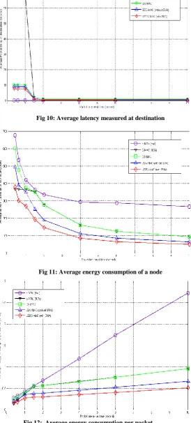
[image:5.595.303.586.50.791.2]43 Fig. 11 shows the average energy consumption of a node.
Comparing the result with DSMAC, DDC-MAC always saves more energy than DSMAC i.e. in low traffic scenario as well as high traffic scenario, and this point out that DDC-MAC provides a better solution than DSMAC. For example, in the test with 4 secs inter-arrival period (low traffic), DDC-MAC reduces energy consumption by 31% SMAC from DSMAC. For example, in the test with .6 secs inter-arrival period (high traffic), DDC-MAC reduces energy consumption by 18% from DSMAC.
Comparing the DDC-MAC with SMAC (10%), DDC-MAC tends to decrease the duty cycle when utilization, which is related to traffic load, is lower, this results in more significant energy saving than SMAC (10%). For example, in the test with 4 secs inter-arrival period, DDC-MAC reduces energy consumption by 31% from SMAC (10%). When the traffic load is higher energy consumption of DDC-MAC is increased. For example, in the test with .6 secs inter-arrival period, DDC-MAC increases energy consumption by 6% but it significantly reduces latency by 85% from SMAC (10%). Therefore, DDC-MAC is suitable for high traffic delay-sensitive sensor applications only. Comparing the DDC-MAC with UDDC-MAC, in UDDC-MAC average eneragy consumption of a node is always less than DDC-MAC. For example, in the test with .6secs inter-arrival period, UMAC decreases the energy consumption by 23% from DDC-MAC.
Comparing the MAC with S-MAC (10%), UDDC-MAC results in more significant energy saving in both high traffic scenario and low traffic scenario. For example, in the test with 4 secs inter-arrival period, DDC-MAC reduces energy consumption by 47% from SMAC (10%). For example, in the test with .6 secs inter-arrival period, UDDC-MAC decreases energy consumption by 18% as well as it significantly reduces latency by 85% from SMAC (10%). Therefore UDDC-MAC is suitable for high traffic energy-efficient delay-sensitive sensor applications.
Fig. 12 shows the average energy consumption per packet. When the traffic load is higher average energy consumption per packet of UMAC is more or less same as DDC-MAC, DSDDC-MAC, and SMAC (10%). When the traffic load is lower average energy consumption per packet of UDDC-MAC is significantly reduced. For example, in the test with 4 secs inter-arrival period, average energy consumption per packet of UDDC-MAC is reduced by 45% from SMAC, DSMAC and 23% from DDC-MAC. Therefore this protocol is suitable for energy efficient delay-sensitive WSNs
6.
CONCLUSION
In this paper, DDC-MAC and UDDC-MAC protocols have been proposed. The tradeoff between energy and latency is an important issue in the sensor networks. Due to the limitation in sensor battery supply, it is not efficient to keep sensors active over all time. On the other hand, some sensor applications may desire a small latency. Simulation of the proposed protocols show improved latency performance with the energy consumption at a reasonable level. For example, in the test with 0.6 secs inter-arrival period, DDC-MAC consumes by 6% more energy than S-MAC (10%) but it significantly reduces latency by 85% as compared to SMAC (10%). Therefore, DDC-MAC is suitable for high traffic delay-sensitive sensor applications only. UDDC-MAC decreases energy consumption by 18% compared to S-MAC (10%) and significantly reduces latency by 85%. Therefore
[image:6.595.313.582.112.429.2]UDDC-MAC is suitable for high traffic energy-efficient delay-sensitive sensor applications.
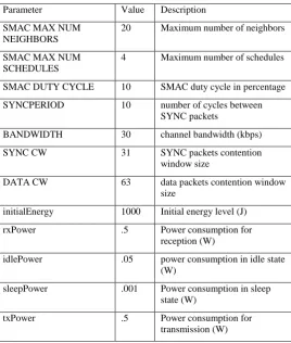
Table 1: Simulation Parameters
Parameter Value Description
SMAC MAX NUM NEIGHBORS
20 Maximum number of neighbors
SMAC MAX NUM SCHEDULES
4 Maximum number of schedules
SMAC DUTY CYCLE 10 SMAC duty cycle in percentage
SYNCPERIOD 10 number of cycles between SYNC packets
BANDWIDTH 30 channel bandwidth (kbps)
SYNC CW 31 SYNC packets contention
window size
DATA CW 63 data packets contention window
size
initialEnergy 1000 Initial energy level (J)
rxPower .5 Power consumption for
reception (W)
idlePower .05 power consumption in idle state (W)
sleepPower .001 Power consumption in sleep state (W)
txPower .5 Power consumption for
transmission (W)
Fig 10: Average latency measured at destination
[image:7.595.22.297.107.715.2]Fig 11: Average energy consumption of a node
Fig 12: Average energy consumption per packet
7.
REFERENCES
[1] I. F. Akyildiz, W. Su, Y. Sankarasubramaniam, et al., “Wireless Sensor Networks: A survey,” Elsevier Journal on Computer Networks, Vol. 38, No. 4, pp. 393-422, March 2002.
[3] W. Ye, J. Heidemann and D. Estrin, “An energy-efficient MAC protocol for wireless sensor networks,” in Proceedings of IEEE INFOCOM, pp. 1567–1576, June 2002.
[5] W. Lee, M. V. Nguyen, A.V. Hwang, et al., “Schedule Unifying Algorithm Extending Network Life in S-MAC- Based Wireless Sensor Networks,” IEEE Transaction on Wireless Communications, Vol. 8, No. 9, pp. 4375-4379, September 2009.
[6] Gaurav, An Energy Efficient Medium Access Control For Wireless Sensor Network, M.Tech Thesis, Department of Electronics and Computer Engineering, IIT Roorkee, June 2008.
[7] A. Barroso, U. Roedig and C. Sreenan, “μ-MAC: An Energy Efficient Medium Access Control for Wireless Sensor Networks,” in Proceedings of the Second European Workshop on Wireless Sensor Networks, pp. 70 – 80, 2005.
[8] C. Sungrae, K. Kanuri and J. Cho, “Dynamic Energy Efficient TDMA-based MAC Protocol for Wireless Sensor Networks,” Autonomic and Autonomous Systems and International Conference on Networking and Services, ICASICNS, 2005.
[9] L. Campelli, A. Capone and M.Cesana “A Receiver Oriented MAC Protocol for Wireless Sensor networks,” IEEE International Conference of Mobile Adhoc and Sensor Systems, pp. 1-10, September 2007.
[10] T.H. Hsu and P.Y. Yen, “Adaptive time division multiple access-based mediumaccess control protocol for energy conserving and datatransmission in wireless sensor networks”, IET Journal on Communications, Vol. 6, No. 5, pp. 2662-2672, December 2011.
[11] T. V. Dam and K. Langendoen, “An adaptive energy efficient MAC protocol for wireless sensor networks,” in Proceedings of the First ACM Conference on Embedded Networked Sensor Systems, pp. 171–180, November 2003.
[12] S. Ray, I. Demirkol and W.Heinzelman, “ADV-MAC: Advertisement-based MAC Protocol forWireless Sensor Networks”, Fifth International Conference on Mobile Ad-hoc and Sensor Networks, pp. 265-272, December 2009.
[13] X. Wang, J. Min, Y. Zhou, et al., “A Traffic-aware MAC protocol based on dynamic contention windows in Wireless Sensor Networks”, 7th International Conference on Wireless Communications, Networking and Mobile Computing, pp. 1-7, September 2011.
[14] L. Liang, D. Gao, Y. Qin, et al., “An adaptive congestion-aware MACprotocol for wireless sensor networks”, 3rd IEEE International Conference on Broadband Networks and Mutlimedia Technology, pp. 1074-1078, October 2010.
45 of the IEEE International Conference on Information and
Automation, pp. 1538-1543, June 2010.
[16] X.Hongyu and S.Wonho, “A Traffic Adaptive Sleep MAC Protocol for WirelessSensor Network”, International Conference on Information and Communication Technology Convergence, pp. 256-257, November 2010.[2] K.Romer and F. Mattern, “The