© 2017, IRJET | Impact Factor value: 5.181 | ISO 9001:2008 Certified Journal | Page 597
Numerical Modelling of Concrete Filled Frp Tubes Subjected Under
Impact Loading
Shine Ancy Cherian
1, Afia S Hameed
21
PG Student, Department of Civil Engineering, SAINTGITS College of Engineering, Kottayam, Kerala, India
2Assistant Professor Department of Civil Engineering, SAINTGITS College of Engineering, Kottayam, Kerala, India
---***---Abstract -
Numerous experimental investigations have demonstrated the advantages of Concrete Filled FRP Tubes (CFFTs) over, reinforced concrete members under various loading conditions. However none of this studies investigated whether the advantages of CFFTs extends to resist dynamic loads. The high strength to weight ratio of FRP tubes makes them desirable as construction materials. Hollow thin tubes rarely achieve their maximum strength, since they fail prematurely by local buckling. Filling the tubes with concrete is a solution to this problem. Previous research shows that encasing concrete members in a FRP tube protected the concrete and increased the member’s strength. This paper outlines a numerical model built using commercially available software ANSYS 17, in order to predict the response of concrete filled Glass fiber reinforced polymer (GFRP) tubes (CFFTs) and regular round reinforced concrete members to dynamic impact loading. A parametric study is conducted to investigate the effects of thickness of GFRP (Glass Fibre Reinforced Polymer) on the response of CFFTsKey Words: Concrete filled FRP tube (CFFT),
Fibre-reinforced polymer (FRP) tube, Reinforced concrete
1. INTRODUCTION
Civil engineering structures are usually treated in a static manner, in which the applied forces are in equilibrium and they do not produce any dynamic motion. In the case of impact loading, the applied forces are not in equilibrium; thus the structure is set in motion, hence requiring a dynamic analysis to determine response. This dynamic situation requires adjusting the design process, especially in cases where the rate of motion is rapid, since the behavior of construction materials, such as steel and concrete, is rate dependent. Extensive researches show that casting reinforced concrete into FRP tubes increases the structural performance of the system when compared to individual components under static conditions. While the FRP tube’s geometry makes it susceptible to buckling and reinforced concrete is easily cracked and damaged. In addition to the strength and confinement that the FRP tube provides, it contains and protects the concrete. Thus it is evident that the containment and protection of the concrete core by the FRP tube makes it suitable for impact resistant design. This
motivated in investigating the behavior under impulsive dynamic impact loading.
The behaviour of plain and reinforced concrete under impact has been studied for decades such as by Banthia et al. [6] and Bentur et al. [8] and the difficulties in testing and analysis have been recognized and reported by Banthia et al. [7] where they presented details of an impact testing machine in the hope of standardizing the testing procedure. Additionally, the need for a simplified impact design procedure has been recognized and addressed by Kishi and Mikami [2] who developed simplified empirical equations relating the static flexural capacity, impact energy, and either the maximum or the residual displacement. The potential of FRP for improving impact resistance has also been recognized and investigated by researchers such as Tang et al [5] and Yazan and Qaswari [1] who reported favourable results
1.1 CFFT(concrete filled glass fibre reinforced
polymer tubes
)© 2017, IRJET | Impact Factor value: 5.181 | ISO 9001:2008 Certified Journal | Page 598
geometric non-linearity’s. The study investigated the
effect of the diameter, length, and tube thickness on the
combined axial and moment capacities of the
cantilevers.
2. VALIDATION
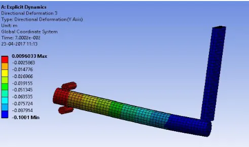
[image:2.595.304.562.245.634.2]Experiments conducted Yazan Qasrawi (2015) [8] using ANSYS 17 Explicit Dynamics was used for the validation purpose. The first specimen of 4m length and 209mm diameter with four 10M longitudinal bars having tensile yield strength of 430 MPa, ultimate strength of 577MPa and young’s modulus of 170GPa is taken (Fig1).The specimen has a continuous steel spiral shear reinforcement of 6mm with a spacing of 0.1m.At the ends within o.2m the spacing is 0.05m and has a tensile yield strength of 645MPa,ultimate strength of 713 MPa and young’s modulus of 194GPa.The concrete used has a compressive strength of 34MPa.The impact hammer used is standard 4340steel with a density of 10g.cm-3 and a weight of 561kg.The velocity in Y direction is taken as 1.35m/s downwards. The experimental value obtained in paper Yazan Qasrawi (2015)[1] is 0.92m and the numerical value obtained as per this study is 0.100m(Fig-1).Therefore the percentage of difference is 6.3%
Fig -1: Deformation In The Mid Span Due To Hammer Impact
3. FINITE ELEMENT MODELLING
The FE modelling is conducted in ANSYS 17 (Explicit Dynamics).The RC column is having a of length 4000mm and diameter 300mm is adopted.The Longitudinal reinforcement is 8no.’s of 12mm diameter .The stirrups are 8mm continuous steel spiral shear reinforcement to prevent shear failure and maximize ductility. The spiral spacing was 0.03 m except within 0.2 m of the ends where it was reduced to 0.015 m to mitigate the effects of the support reactions. The concrete used is M-35 concrete with RHT concrete properties with 35MPa compressive strength. The steel material used is standard 4340 steel grade .The GFRP material with elastic modulus of 40.2GPa and Poisson’s ratio 0.2 is used for the study.Reinforced concrete specimen is
[image:2.595.38.284.419.564.2]impacted at mid-span in a three-point bending with a centre-centre span of 3.85m.The specimen is restrained with additional rollers at the supports to prevent rebounding. The impact hammer weighted 561 kg is dropped from incrementally increasing heights on each specimen until failure occurred. The testing is carried out for two heights 0.15mand 0.51m.The corresponding velocities are 1.7m/s and 3.6m/s. The ply angle criteria adopted is shown in table 1.The mesh size being used is 40mm.
Table -1: Models used in the study SL
NO
Specimen Designation
1 Normal Column tested under a height of 0.15m
NCH1
2 Normal Column tested under a height of 0.51m
NCH2
3 Normal Column Confined with GFRP tube of 2mm thickness tested under a height of 0.15m
NCG2H1
4 Normal Column Confined with GFRP tube of 4mm thickness tested under a height of 0.15m
NCG4H1
5 Normal Column Confined with GFRP tube of 2mm thickness tested under a height of 0.51m
NCG2H2
6 Normal Column Confined with GFRP tube of 4mm thickness tested under a height of 0.51m
© 2017, IRJET | Impact Factor value: 5.181 | ISO 9001:2008 Certified Journal | Page 599 Table -2: Ply Angle Criteria
4. RESULTS and DISCUSSION
4.1 Comparison of directional deformation of GFRP
confined column and normal column, tested under
the impact height H1
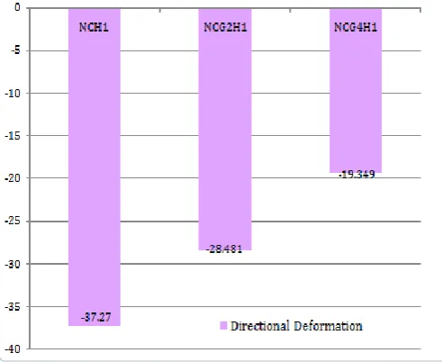
[image:3.595.309.553.306.481.2]In order to compare the directional deformation, the GFRP confined columns and the normal columns are tested under the impact heights H1 and H2.The corresponding deformation values are obtained. For the impact height H1, the deformation for GFRP confined column is less when compared to normal column. As the thickness of the GFRP confinement increases the directional deformation decreases. For normal column the directional deformation is -37.27mm. For column confined with GFRP tube of 2mm thickness, deformation is -28.481mm. For column confined with GFRP tube of 4mm thickness, deformation is -19.349mm.
Fig -2: Directional Deformation of NCH1
[image:3.595.310.556.517.718.2]Fig -3: Directional Deformation of NCG2H1
Fig -4: Directional Deformation of NCG4H1
Chart-1: Comparison of Directional Deformation Thickness of GFRP
tube
Ply Angle
2mm 0°,45°
[image:3.595.35.272.530.696.2]© 2017, IRJET | Impact Factor value: 5.181 | ISO 9001:2008 Certified Journal | Page 600 Chart-2: Directional Deformation Versus Time Graph
4.2 Comparison of directional deformation of GFRP
confined column and normal column, tested under
the impact height H2
[image:4.595.308.550.304.485.2]In order to compare the directional deformation, the GFRP confined columns and the normal columns are tested under the impact heights H1 and H2.The corresponding deformation values are obtained. For the impact height H2
,
the
deformation for GFRP confined column is less when compared to normal column. As the thickness of the GFRP confinement increases the directional deformation decreases. For normal column the directional deformation is -68.931mm. For column confined with GFRP tube of 2mm thickness, deformation is -49.572mm. For column confined with GFRP tube of 4mm thickness, deformation is -38.18mm.Fig -5: Directional Deformation of NCH2
[image:4.595.311.551.522.728.2]Fig -6: Directional Deformation of NCG2H2
Fig -7: Directional Deformation of NCG4H2
[image:4.595.37.282.550.693.2]© 2017, IRJET | Impact Factor value: 5.181 | ISO 9001:2008 Certified Journal | Page 601 Chart-4: Directional Deformation Versus Time Graph
5. CONCLUSIONS
From the analysis carried out as part of the study on effect of confinement of concrete filled FRP columns, it was observed that CFFT have several distinct advantages over reinforced concrete column under dynamic loading. The ply angle also affects the behaviour under impact loading. As the thickness of the FRP tube increases, the directional deformation decreases .For column confined with GFRP tube of 2mm thickness, the percentage difference is 23.58%, compared with that of normal column ,when tested under the impact height H1.For column confined with GFRP tube of 4mm thickness, the percentage difference is 48.08%, compared with that of normal column, when tested under the impact height H1.For column confined with GFRP tube of 2mm thickness, the percentage difference is 28.08%,compared with that of normal column, when tested under the impact height H2.For column confined with GFRP tube of 2mm thickness, the percentage difference is 44.61%,compared with that of normal column, when tested under the impact height H2
ACKNOWLEDGEMENT
The authors express heartfelt and sincere gratitude to God Almighty; also we would like to express our sincere thanks to all the teachers and staffs of the Department of Civil engineering, SAINTGITS College of Engineering. Big thanks to all my friends who kept on inspiring the work.
REFERENCES
[1] Yazan Qasrawi and Pat J. Heffernan, " Numerical
Modeling of Concrete-Filled FRP Tubes’ Dynamic Behaviour under Blast and Impact Loading," ACI Structural Journal, vol. 19, No. 113, (2015): 370-383.
[2] N. Kishi and H. Mikami, "Empirical Formulas for
Designing Reinforced Concrete Beams under Impact Loading," ACI Structural Journal, vol. 109, No. 4, (2012): 509-519.
[3] A. Fam, Y. J. Kim and J. Son, "A numerical investigation
into the response of free end tubular composite poles subjected to axial and lateral loads," Thin-Walled Structures, vol. 48, (2010):650 – 659.
[4] J. Son and A. Fam, "Finite element modeling of hollow
and concrete-filled fiber composite tubes in flexure: Model development, verification and investigation of tube parameters," Engineering Structures, vol. 30, (2008):2656–2666.
[5] T. Tang and H. Saadatmanesh, "Behavior of Concrete
Beams Strengthened with Fiber-Reinforced Polymer Laminates Under Impact Loading," ASCE Journal of Composites for Construction, vol. 7, No. 3, (2003): 209-218.
[6] N. Banthia, S. Mindess, A. Bentur and M. Pigeon, "Impact
Testing of Concrete Using a Drop-Weight Impact Machine," Experimental Mechanics, (1989):63-60.
[7] N. P. Banthia, S. Mindess and A. Bentur, "Impact
Behaviour of Concrete Beams,"Materials and Structures, vol. 20, (1987):293-302.
[8] A. Bentur, S. Mindess and N. Banthia, "The Behaviour of