© 2018, IRJET | Impact Factor value: 6.171 | ISO 9001:2008 Certified Journal | Page 1358
Methods for improved efficiency in dc-dc buck converter
Mishu Devadasan
1, Alpesh M. Patel
21 P.G. Student, VLSI and Signal Processing (EC), VGEC-Chandkheda, Gujarat, India
2Asst. Prof., Electronics and Communication Engineering, VGEC-Chandkheda, Gujarat, India
---***---Abstract -
Switching mode DC/DC converters are crucialbuilding blocks in portable devices and therefore their power efficiency, accuracy and cost are the major issues. Switching converters gained popularity in powering portable devices because of their high efficiency, compact sizes and high current delivery capability. However, such portable devices for most of the time operate at light loads and are only required to deliver high current for short periods, while conventional buck converter suffers from low efficiency during light load condition due to the switching losses that do not scale with load current. In this research, various techniques for efficiency improvement of buck converter is presented.
Key Words: DC/DC Converter, Buck, SMPS, Compensation
Network, VMC, CMC, ESR, Pulse Width Modulation (PWM),PMIC (Power Management IC)
1. INTRODUCTION
Employing DC/DC converters can be viewed as a method to generate multiple voltage levels from a single DC supply voltage to feed the different sub-circuits in the device. This method of generating multiple voltage levels from a single battery source can reduce the device area considerably. While on the other hand DC voltage directly provided by battery or rectifier, besides containing high voltage ripples also is not constant enough, thus it is not applicable for most devices. DC/DC regulators are employed to attenuate the ripples regardless of change in the load current or input voltage [1].
Due to ever increasing demand from power systems has placed power consumption as the primary concern. To keep up with these demands, engineers have dedicated immense and numerous work towards developing efficient conversion techniques. However, the efficiency is not always maximized, but varies according to the size of load. Hence improving light-load efficiency is critical for portable devices.
1.1 Switched Mode Power Supply (SMPS)
Switching-mode power supply which is also called as switching-mode DC to DC converter is a type of power supply which uses switches (usually in the form of transistor) and low loss components such as inductors, capacitors and transformers for regulating output voltage [2]. The circuit of SMPS consists of two main parts: power stage and control part as shown in fig 1 . Nowadays most of the work is done on control part for better regulation of output voltage, whereas the power part has not undergone many changes. Generally
MOSFET is used as a power switch in SMPS for stabilizing output voltage. The switches are not conducted continuously and they operate under specific frequency, therefore they are useful for conservation of battery life and reduction of the power loss in the circuit.
Fig -1: Block diagram of SMPS
1.2 High Efficiency
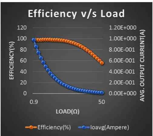
Efficiency is the most critical and important parameter for any power supply. A lot of work has been published in the field of improving efficiency. Since the efficiency of buck converter drops both at light load and at heavy load as shown in fig 2, the research is divided into two directions depending on different applications. Applications such as battery-powered portable devices need to be designed for high efficiency over entire load ranges extended from light load to heavy load, and especially at the light load range, since they operate at this region most of the time. This paper is targeting at these applications and working on improving light-load efficiency.
2. TECHNIQUES AND CONTROL SCHEMES
[image:1.595.311.558.249.383.2]© 2018, IRJET | Impact Factor value: 6.171 | ISO 9001:2008 Certified Journal | Page 1359 Fig -2: Efficiency vs Load
Before switch turn-off instant, an auxiliary switch is turned on and the main switch current is reduced to zero. In ZVS technique, a capacitor is placed in parallel with the main switch to provide soft switching condition for switch turn-off [3]-[5]. In this technique, soft switching condition for switch turn-on is achieved by an auxiliary switch, which discharges the snubber capacitor across the main switch. Soft-switching techniques typically increase the current and/or voltage stresses in the semiconductor devices. ZVS techniques typically increase the voltage stress of the active switches, and ZCS techniques increase current stresses. Furthermore, the auxiliary large and lossy inductor and capacitor make these techniques poor candidates for on-chip implementation applications.
To improve the output transient response of buck converter, numerous control topologies are proposed for different applications. Faster recovery time and/or smaller voltage overshoot/undershoot, as well as simpler implementations and smaller sizes are targeted. Traditional control techniques, such as pulse width modulation (PWM) and pulse frequency modulation (PFM), still have margin for improvement. For example, [18] propose a pseudo-Type III compensation for PWM voltage-mode buck converter, which mimics the frequency response of a Type III compensator. Type III compensator provides two zeroes and two poles by adding large value resistors and capacitors to stable the loop, which is area consuming. The pseudo-Type III compensation in [6] is able to be implemented without resistors and capacitors, thus tremendously reduces the chip area and power consumption. Hysteretic control techniques are alsopopular due to advantages in their simplicity, immediate response to a line/load transient and unconditional stability under all operation conditions. Their main disadvantages are switching frequency varies with design parameters, and the inductor current may go beyond the current limit of the power switches during large signal transient response [7]-[9].
Although analog controllers are still the mainstream control schemes, digital control has gained popularity recent years due to its robustness to noise, lower sensitivity to parameter variations and programmability along with its ability to implement sophisticated control schemes [10]-[11]. The main concern in digital control is how to match the dynamic performance of their analog counterparts [11]-[14]. ADC which digitizes the error signal and digital PWM generator (DPWM) are the main building blocks and the most challenging circuits to design digital control [15]-[19].
3. EFFICIENCY IMPROVING IN LIGHT LOAD CONDITIONS
3.1 PFM
The most frequently used method to improve light-load efficiency is to employ pulse frequency modulation (PFM) control mode [43], [21]-[29]. Since switching loss is proportional to switching frequency, by scaling down the switching frequency together with load current, PFM mode is able to reduce the switching losses, and maintains high light-load efficiency. The main problem with PFM mode is the varying switching frequency causes more severe Electronic magnetic interference (EMI), making it unsuitable for noise-sensitive RF circuits in portable devices.
3.2 Pulse Skipping Mode
Another prevailing method in industry is pulse skipping modulation (PSM) [30]-[32]. in PSM mode, control signal will skip some clock cycles as the load decreases. the equivalent switching frequency is reduced, resulting in increased light-load efficiency.
3.3 Burst Mode
Burst mode technique is also commonly used in improving light-load efficiency [33]. When configured for this mode and during light load, the converter will alternate between ON and OFF state. During ON state, the controller bursts out a few pulses to maintain the charge voltage on the output capacitor. During OFF stare, it turns off the converter and goes into sleep mode with most of internal circuits shut down. One drawback of burst mode is an additional low frequency ripple added on the output voltage during ON state.
3.4 Mode-Hopping
[image:2.595.35.288.75.299.2]© 2018, IRJET | Impact Factor value: 6.171 | ISO 9001:2008 Certified Journal | Page 1360 3.5 Gate Drive Technique
In [42], [34]-[35], a gate drive technique was presented whereby the gate voltage swing statically reduced or dynamically scales with load current such that the gate drive loss reduces at light load. The main problem with this technique is that it only reduces the gate-drive loss, but not the switching loss due to switch the switching node.
3.6 Other Techniques
There are several other techniques to get power loss reduction at light load condition, such as width controlling technique [20], [33]-[36], dead-time controlling technique [37]-[41].
4. PROBLEM STATEMENT
DC-DC Buck Converter faces low efficiency during light load conditions.
4. CONCLUSION
Hence various techniques to improve efficiency during light load conditions have been studied.
REFERENCES
[1] Marian K. Kazimierczuk, “Pulse-width Modulated DC-DC Power Converters”, Edition, Wiley.
[2] Jerrold Foutz, “Switching-Mode Power Supply Design Tutorial Introduction”, SMPS Technology, http://www.smpstech.com/tutorial/t01int.htm , accessed: July 2017.
[3] E. Adib, and H. Farzanehfard, “Zero-voltage-transition PWM converters with synchronous rectifier,” IEEE Transactions on Power Electronics, vol. 25, no. 1, pp. 105-110, January 2010.
[4] H. Mao, O. Abdel Rahman, and I. Batarseh, “Zero-voltage-switching DC-DC converters with synchronous rectifiers,” IEEE Transactions on Power Electronics, vol. 23, no. 1, pp. 369-378, January 2008.
[5] C.-Y. Chiang, and C.-L. Chen, “Zero-voltage-switching control for a PWM buck converter under DCM/CCM boundary,” IEEE Transactions on Power Electronics, vol. 24, no. 9, pp. 2120-2126, September 2009.
[6] P. Y. Wu, S. Y. S. Tsui, and P. K. T. Mok, “Area- and power-efficient monolithic buck converters with pseudo-type III compensation,” IEEE Journal of Solid-State Circuits, vol. 45, no. 8, pp. 1446-1455, August 2010.
[7] F. Su, W.-H. Ki, and C.-Y. Tsui, “Ultra fast fixed-frequency hysteretic buck converter with maximum charging current control and adaptive delay compensation for DVS applications,” IEEE Journal of Solid-State Circuits, vol. 43, no. 4, pp. 815-822, April 2008.
[8] M. Castilla, L. G. de Vicuña, J. M. Guerrero, Member, IEEE, Jaume Miret, and Nestor Berbel, “Simple low-cost hysteretic controller for single-phase synchronous buck converters,” IEEE Transactions on Power Electronics, vol. 22, no. 4, pp. 1232-1241, July 2007.
[9] P. Li, L. Xue, P. Hazucha, T. Karnik, and R. Bashirullah, “A delay-locked loop synchronization scheme for high-frequency multiphase hysteretic DC-DC converters,” IEEE Journal of Solid-State Circuits, vol. 44, no. 11, pp. 3131-3145, November 2009.
[10] M. Shirazi, R. Zane, and D. Maksimovic, “An autotuning digital controller for DC-DC power converters based on online frequency-response measurement,” IEEE Transactions on Power Electronics, vol. 24, no. 11, pp. 2578-2588, November 2009.
[11] M. Y.-K. Chui, W.-H. Ki, and C.-Y. Tsui, “A programmable integrated digital controller for switching converters with dual-band switching and complex pole-zero compensation,” IEEE Journal of Solid-State Circuits, vol. 40, no. 3, pp. 772-780, March 2005.
[12] L. Corradini, E. Orietti, P. Mattavelli, and S. Saggini, “Digital hysteretic voltage-mode control for DC-DC converters based on asynchronous sampling,” IEEE Transactions on Power Electronics, vol. 24, no. 1, pp. 201-211, January 2009.
[13] T. Liu, H. Yeom, B. Vermeire, P. Adell, B. Bakkaloglu, “A digitally controlled DC-DC buck converter with lossless load-current sensing and BIST functionality,” IEEE Int. Solid-State Circuits Conf. (ISSCC), Session 22, pp. 388–389, February 2011.
[14] Y. Qiu, H. Liu, and X. Chen, “Digital average current-mode control of PWM DC-DC converters without current sensors,” IEEE Transactions on Industrial Electronics, vol. 57, no. 5, pp. 1670-1677, May 2010.
© 2018, IRJET | Impact Factor value: 6.171 | ISO 9001:2008 Certified Journal | Page 1361 [16] F. Kuttner, H. Habibovic, T. Hartig, M.
Fulde, G. Babin, A. Santner, P. Bogner, C. Kropf, H. Riesslegger, U. Hodel, “A digitally controlled DC-DC converter for SoC in 28nm CMOS,” IEEE Int. Solid-State Circuits Conf. (ISSCC’11), Session 22, pp. 384-385, February 2011.
[17] J. Xiao, A. Peterchev, J. Zhang, S. Sanders, “A 4uA-quiescent-current dual-mode buck converter IC for cellular phone applications,” IEEE Int. Solid-State Circuits Conf. (ISSCC’04), Session 15, pp. 280-528, February 2004.
[18] M. Barai, S. Sengupta, and J. Biswas, “Dual-mode multiple-band digital controller for high-frequency DC-DC converter,” IEEE Transaction on Power Electronics, vol. 24, no. 3, pp. 752-766, March 2009.
[19] M. Barai, S. Sengupta, and J. Biswas, “Digital controller for DVS-enabled DC-DC converter,” IEEE Transaction on Power Electronics, vol. 25, no. 3, pp. 557-573, March 2010.
[20] O. A.-Rahman, J. A. Abu-Qahouq, L. Huang, and I. Batarseh, “Analysis and design of voltage regulator with adaptive FET modulation scheme and improved efficiency,” IEEE Transaction on Power Electronics, vol. 23, no. 2, pp. 896-906, March 2008.
[21] T. Y. Man, P. K. T. Mok, M. Chan, “An Auto-Selectable-Frequency Modulator for buck converters with Improved Light-Load Efficiency”, IEEE Int. Solid-State Circuits Conf. (ISSCC’08), Section 24, pp. 440-626, February 2008.
[22] W. Liou, M. Yeh, and Y. L. Kuo, “A high efficiency dual-mode buck converter IC for portable applications”, IEEE Transactions on Power Electronics, vol. 23, no.2, pp. 667-677, March 2008.
[23] TPS62320 500-mA, 3-MHz Syschronous Step-Down Converter in Chip Scale Packaging Datasheet, Texas Instruments, November 2007. [Online]. Available: http://www.ti.com. [Accessed: February 11, 2011].
[24] ADP2108 Compact, 600mA, 3MHz, Step-Down DC-to-DC converter Datasheet Rev. E, Analog Devices, October 2010. [Online]. Available: http://www.analog.com. [Accessed: February 11, 2011].
[25] LTC3542 500mA, 2.25MHz Synchronous Step-Down DC/DC converter Datasheet Rev. A, Linear Technology, November 2006. [Online]. Available: http://www.linear.com. [Accessed: February 11, 2011].
[26] MAX8560 4MHz, 500mA Synchronous Step-Down DC-DC converters in Thin SOT and TDFN Datasheet Rev. 2, Maxim, August 2005. [Online]. Available: http://www.maximtec.com. [Accessed: February 11, 2011].
[27] SC192 Synchronous buck converter with Integrated Power Devices Datasheet Rev. 8, Semtech Corporation, March 2007. [Online]. Available: http://www.semtech.com. [Accessed: February 11, 2011].
[28] MCP1603 2.0MHz, 500mA Synchronous buck Regulator Datasheet, Microchip Technology Inc., 2007. [Online]. Available: http://www.microchip.com. [Accessed: February 11, 2011].121
[29] NCP1523 3MHz, 600 mA, High-Efficiency, Adjustable Output Voltage Step-down converter Datasheet Rev. 2, ON Semiconductor, February 2007. [Online]. Available: http://www.onsemi.com. [Accessed: February 11, 2011].
[30] P. Sandri, Milan; Maria Rosa Borghi, Marcallo con Casone; Luca Rigazio, Cigliano, “DC-to-DC converter functioning in a pulse-skipping mode with low power consumption and PWM inhibit,” US Patent, US005745352A, April 1998. [Online]. Available: http://www.freepatentonline.com. [Accessed: February 11, 2011].
[31] V. Peterchev, and S. R. Sanders, “Digital multimode buck converter control with loss-minimizing synchronous rectifier adaptation,” IEEE Transactions on Power Electronics, vol. 21, no. 6, pp. 1588-1599, November 2006.
[32] S. Angkititrakul and H. Hu, “Design and analysis of buck converter with pulse-skipping modulation,” IEEE Power Electronics Specialists Conference, pp. 1151-1156, June 2008.
[33] J. M. Esteves, and R. G. Flatness, “Adjustable minimum peak inductor current level for burst mode in current-mode DC-DC regulators,” US Patent, US00RE41037E, December 2009. [Online]. Available: http://www.freepatentonline.com. [Accessed: February 11, 2011].
[34] M. D. Mulligan, B. Broach, and T. H. Lee, “A constant-frequency method for improving light-load efficiency in synchronous buck converters,” IEEE Power Electronic Letter, vol. 3, no. 1, pp. 24-29, March 2005.
© 2018, IRJET | Impact Factor value: 6.171 | ISO 9001:2008 Certified Journal | Page 1362 on Industrial Electronics (ISIE’09), pp. 1066-1070,
July 2009.
[36] K.-H. Chen, C.-C. Chien, C.-H. Hsu, and L.-R. Huang, “Optimum power-saving method for power MOSFET width of DC-DC converters,” IET Proc. Circuits, Devices Syst., vol. 1, no. 1, pp. 57–62, February 2007.
[37] O. Trescases, W. T. Ng, H. Nishio, M. Edo, and T. Kawashima, “A digitally controlled DC-DC converter module with a segmented output stage for optimized efficiency,” in Proc. IEEE Int. Symp. Power Semiconductor Devices and Integrated Circuits (ISPSD), pp. 1–4, June 2006.
[38] H.-W. Huang, K.-H. Chen, and S.-Y. Kuo, “Dithering skip modulation, width and dead time controller in highly efficient DC-DC converters for system-on-chip applications,” IEEE Journal of Solid-State Circuits, vol. 42, no. 11, pp. 2451–2466, November 2007.
[39] H. Lee, and S.-R. Ryu, “An efficiency-enhanced DCM buck Regulator with improved switching timing of power transistors,” IEEE Transactions on Circuits and Systems—II: Express Briefs, vol. 57, no. 3, pp. 238-242, March 2010.
[40] S. Lee, S. Jung, J. Huh, C. Park, C. Rim, G. Cho, “Robust and efficient synchronous buck converter with near-optimal dead-time control,” IEEE Int. Solid-State Circuits Conf. (ISSCC), Session 22, pp. 392-393, February 2011.
[41] W. Yan, C. Pi, W. Li and R. Liu, “Dynamic dead-time controller for synchronous buck DC-DC converters,” Electronic Letter, vol. 46, Issue 2, pp. 164-164, January 2010.
[42] V. Kursun, S. G. Narendra, V. K. De, and E. G Friedman, “Low-voltage-swing monolithic DC-DC conversion,” IEEE Transactions on Circuits and Systems II, vol. 51, no. 5, pp. 241-248, May 2004.