© 2017, IRJET | Impact Factor value: 5.181 | ISO 9001:2008 Certified Journal
| Page 1809
UTILIZATION OF EXHAUST GAS OF VEHICLE FOR ELECTRICITY
GENERATION
Shaikh Mobin A.
1,Shaikh Saif A.
2, Shaikh Najim N.
3, Pathan Umar Farooq O.
4,Pathan Farhan A.
51234
Student,Dept. of Mechanical Engineering, G.H. Raisoni College of Engineering and Management,
Ahmednagar, India
[email protected]
Mob.-+918275391196/+919892646888
5
HOD,Dept. of Mechanical Engineering, G.H. Raisoni College of Engineering and Management, Ahmednagar,
India
.
[email protected]
***
ABSTRACT-Energy means capacity to do work. There are various types of energy available in the environment which is made by conventional and non conventional energy sources. The all forms of energies are required for doing various mechanical operations, But now there is large problem of electricity due to low availability energy resources. So in villages there is no maximum electric supply for doing simple operations such as mobile charging power for lamps etc.
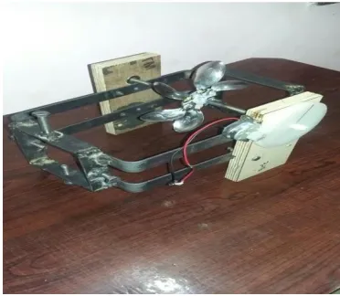
By taking above factors we made the model which can produces electric power by using kinetic energy of exhaust gas of vehicle specially by two wheeler. When the model is in working condition, the runner rotates due kinetic energy of exhaust gas. This runner is attach to large gear by using shaft which further attach to small gear, placed on dynamo finally dynamo produces electric power. This is simple in construction due to it made by local available material.
Key Words : electricity Generation, Exhaust Gas, Kinetic Energy,
1.
INTRODUCTION
Now-a-days technology is moving at a very faster rate. The conventional energy sources like Petrol, Diesel etc. are on a verge of extinction. So scientists are moving towards the use of non-conventional energy resources. But it also requires some kind of energy to convert it into another form. In this project we are utilizing the kinetic energy of exhaust gases of vehicle which is of no use.
Energy means capacity to do work. There are various types of energy available in the environment which is made
by conventional and non conventional energy sources. The all forms of energies are required to doing various mechanical operations, which are related to the agricultural sector. There are mainly use of electric energy is done by cultivator for irrigations operation. But now there is large problem of electricity due to low availability energy resources. So in villages there is no maximum electric supply for doing simple operations such as mobile charging power for lamps etc.
By taking above factors we have made the model which produce electric power by using exhaust gas of vehicle specially two wheeler. In the model, by using kinetic energy of exhaust gas the runner rotates which attach to large gear by using shaft which further attach to small gear, placed on dynamo finally dynamo produces electric power. This is simple in construction due to it made by local available material. By using this waste gas of vehicle this model can work better for the electric power generation. This set up is mainly useful for villages. It can be use as power source at night when output power produced by set up is stored in battery. This set up is easy to handle and cheaper, in concern with everyone.
2.
LITERATURE SURVEY
Generation of Electricity by Using Exhaust from Bike by
© 2017, IRJET | Impact Factor value: 5.181 | ISO 9001:2008 Certified Journal
| Page 1810
Study and performance analysis of charging vehiclebattery using bike exhaust gas by K. Kumaravel, P. Balashanmugam, and G. Balasubramanian[2], They had done different studies according to their practical inputs. They had approached the problem with different engine RPM. Practically for different engine speeds for different turbine power output were observed.
Power Generation by Exhaust Gases On Diesel Engine by
Kranthi Kumar Guduru, Yakoob Kol ipak, Shanker. B and N. Suresh[3]:-. Waste heat recovery entails capturing and reusing the waste heat from internal combustion engine and using it for heating or generating mechanical or electrical work. It would also help to recognize the improvement in performance and emissions of the engine if these technologies were adopted by the automotive manufacturers.
3.
COMPONENTS
3.1 TURBINE:
A turbine is a rotary mechanical device that extracts energy from a steam and converts it into useful work. A turbine is a turbo machine with at least one moving part called a rotor assembly, which is a shaft or drum with blades attached. When the kinetic energy of exhaust gas acts on the blades so that they move and impart rotational energy to the rotor.
Design Calculation of Turbine wheel :-
1)Calculate the net head (H):-
H = Hg-hf
Hg = gross head (m) hf = total head loss (m)
These losses are approximately Equal to 6% of gross head We know that,
ρghg = ρwhw Given,
hw = 3.2cm = 0.032m ρg = 1.25 (density of gas) ρw = 1000
hg = (100080.032)/1.25=25.6m
hg = 25.6m
Where hf 6% of hh
hf = 1.536m
H = 25.6-1.536
H = 24.064m
2)Calculation of flow rate (Q) Q = velocity*area Vf = (2ghg)0.5 =(2*9.81*25.6)0.5 Vf = 22.41 m/s Af = π/4d2 = 3.14*10-4 m2 Q = 22.4*3.14*10-4
Qt = 7.040*10-3 kg/m3
3)Calculation of the input power Pi = ρw*g*Cv2*H*Qt
=1000*9.81*(0.98)2*24.064*7.040*10-3
Pi= 1.596 kw
4)Speed
Ns = 85.49* √
n = Qt/Qn Qn = V1*A Where,
V1 = Cv*√
=0.98*√
V1 = 6.733 m/s
Qn = 6.733*3.14*
Qn = 2.114*10-3 kg.m3 n = 1
Ns = 85.49* √
= 85.49* √
`Ns = 39.467 rpm N = Ns*
√
= 39.467*
√
N = 52.65 rpm
5)Calculation of runner diameter:- D =
*V1
=
© 2017, IRJET | Impact Factor value: 5.181 | ISO 9001:2008 Certified Journal
| Page 1811
6)Bucketi) Axial width
Bw = 3.4*d = 3.4*0.02 = 0.068m = 6.8cm ii) Length (Bl):-
Bl = 3*d = 3*0.02 = 0.06m = 6cm iii) Depth of bucket (Bd):-
Bd =1.2*d = 1.2*0.02 = 0.024 = 2.4cm
7)Number of buckets:- Z=15+
=15+
Z = 15.875 = 16
Fig.1. Turbine Wheel
3.2.SHAFT:
A Shaft is a cylindrical and a solid metal object which commonly goes through and holds other rotating items (e.g. pulleys, gears, bearings). The shaft is also used to transmit the rotational forces.
Calculation for shaft:
Speed of runner N = 400 mm
Weight of runner = 0.270 kg = 2.65 N
Runner diameter = 160 mm
Power received = 1.596 Kw
From table
Torque = 19.20*10-3
P =
=
P = 0.8 Kw = 800Watt
Design torque, Td
Td =
=
= 38.2*103 N.mm
Tangential force acting on turbine wheel
Ft = Ft =
=
= 477.5 N
Normal load acting on the runner
W =
= 508.14 N
Since the turbine wheel is mounted at distance of 140mm from bearing so it simply supported beam with intermediate load therefore banding moment of gear
M =
=
= 35569.8 N.mm
Equivalent twisting moment
Te= √
= √
= 38365.5 N.mm
Te =
*T*d
3
38365.5=
*42*d
3
© 2017, IRJET | Impact Factor value: 5.181 | ISO 9001:2008 Certified Journal
| Page 1812
Fig.2. Shaft3.3 GEARS
Gears are the machine elements that transmit motion by means of successively engaging teeth. The gear teeth is act as a small lever. Gears are the toothed wheels which can be used for transmitting motion and power from one shaft to another shaft.
Spur gears and straight-cut gears are the two simple type of gear. They consist of a cylinder or disk with the teeth projecting radially, and although they are not straight-sided in form, the edge of each tooth is straight and aligned parallel to the axis of rotation. These gears can be meshed together correctly only if they are fitted to parallel shafts.
Design for spur
gear:-Ø= 200 (full depth involutes)
Zp=14 (no. of tooth on pinion)
Zg=98 (no. of teeth on gear)
P= 1.596*103
N=1665 rpm
Material for gear and pinion nylon fiber
Sut=200mpa
Lewis form factor
Yp=0.484-
=0.279
Yg=0.484- =0.456
Service factor Ka=1.25
Load factor Kw =1
Factor of safety =1.5
Deformation factor = 11400C
For grade 8
e = 16+1.25d, where Ø = m+0.25(d)0.5
b = 10m
# beam strength
ςbg = ςbp = = = 66.67 N/mm2
As pinion and gear both are of same material, pinion is weaker than gear, hence necessary to design pinion for bending.
Fb = ςbp.b.m.Yp
= 66.67*10m*m*0.279
Fb = 186m2 N
# Effective load
V=
= 1.22m m/s
Ft = = =
N
Kv =
=
Feff =
=
*
Feff = N
Estimation of module,
In order to avoid bending failure
Fb = Nf. Feff
© 2017, IRJET | Impact Factor value: 5.181 | ISO 9001:2008 Certified Journal
| Page 1813
186m2 = 2397.87+487.56mm = 2.13mm
Selected standard module is m = 2mm
# Dimension of gear pair
M = 5mm
Zp = 14
Zg = 98
B =10m = 10*5 = 50mm
Dp = m.Zp = 2*14= 28mm = 2.8cm
Dg = m.Zg = 2*98 = 196mm = 19.6cm
Ha = 1m = 1*5 = 5mm
Hf = 1.25m = 1.25*5mm
A = ( = = 280mm
Precise estimation of dynamic load by Buckingham’s equation
For grade 8
e = 16+1.25[m+0.25√ ]
For pinion
ep = 16+1.25[2+0.25√ ] =20.45 µm
eg = 16+1.25[2+0.25√ = 22.875 µm
e = ep+eg = 20.15+22.875 = 43.025*10-3µm
The Buckingham’s equation for the dynamic load in the tangential direction is given by.
Fd =
√
Ft =
= 639.34 N
V = 1.22m = 1.22*2 = 2.44 m/s
Ftmax = Ka.Km.Ft = 1.25*4*639.34 = 799.175 N
C = 11400e = 11400*43.025*10-3 = 490.485 N/mm
Fd =
√
Fd = 3523.57 N
Available factor of safety:
Feff = Ka.Km.Ft+Fd
= 1.25*1*639.34+3523.57
Fd = 186(m2) = 186 (22) = 7440
Hence the available fos
Nf =
=
= 1.717 > 1.5
Hence design is also safe
Surface hardness
Q =
=
= 1.75
K = 0.16 [ ]
2
Fw = dp.b.Q.K
= 28*20*1.75*[ ]2
Fw = 980[
]
2
Fw = Nf. Feff ,
980[ ]2 = 1.5*3523*57
BHN = 232.23
BHN = 240
3.4 D.C GENERATOR
In electricity generation, an electric generator is a device that converts mechanical energy to electrical energy. A generator forces electric current to flow through an external
© 2017, IRJET | Impact Factor value: 5.181 | ISO 9001:2008 Certified Journal
| Page 1814
source of mechanical energy. Generators provide nearly all ofthe power for electric power grids
3.5 BEARINGS
A bearing is a machine element that constrains relative motion between moving parts to the desired motion. The design of the bearing may, for example, provide for free linear movement of the moving part or for free rotation around a fixed axis; or, it may prevent a motion by controlling the vectors of normal forces that bear on the moving parts.
Bearings can be classified broadly according to the motions they allow and according to their principle of operation as well as by the directions of applied loads they can handle.
Selection for Bearing
Diameter of Shaft- 11mm
For 11mm shaft diameter following type of bearing are suitable which have bore diameter of 12 mm
1)6001 2)6201 3)6301
We have selected 6001 series bearing because it sustain more static and dynamic load and it is very cheap and easily available in the market
Specification of 6001 bearing:- Bore diameter :-12mm
Outside Diameter :-28mm Width :-8mm
[image:6.612.347.553.62.275.2]Static Load :-220kg Dynamic Load :-400kg
Fig.3. Bearings
4.RESULTS
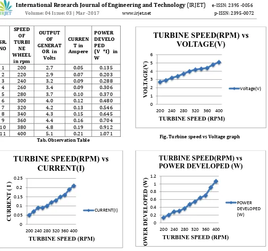
We have done different studies according to our practical inputs. We have approached the problem with different engine RPM. Practically for different engine speeds for different turbine power output were observed.
Different readings at different RPM of the Turbine Wheel are noted as shown below in the table.
[image:6.612.349.535.442.604.2]© 2017, IRJET | Impact Factor value: 5.181 | ISO 9001:2008 Certified Journal
| Page 1815
[image:7.612.39.583.45.555.2]Tab. Observation Table Fig. Turbine speed vs Voltage graph
Fig. Turbine speed vs Current graph Fig. Turbine speed vs Power Developed graph
5.CONCLUSION
The efficiency of the turbine is less, but in optimum design best results can be achieved. Battery charging system from exhaust gas is better idea to save the power. In general the battery is charged through flywheel in which we lost some amount of power. From the experimental investigation, we have observed that the fuel economy can be saved up to a
greater extent. The engine performance is almost same in with and without battery charger
The study also identified the potentials of the technologies when incorporated with other devices to maximize potential energy efficiency of the vehicles. The project carried out by us made an impressing task in the field
0 1 2 3 4 5 6
200 240 280 320 360 400
V
OL
T
AG
E
(V
)
TURBINE SPEED (RPM)
TURBINE SPEED(RPM) vs
VOLTAGE(V)
Voltage(V) 0 0.05 0.1 0.15 0.2 0.25200 240 280 320 360 400
CU
RR
E
NT
( I )
TURBINE SPEED (RPM)
TURBINE SPEED(RPM) vs
CURRENT(I)
CURRENT(I) 0 0.2 0.4 0.6 0.8 1 1.2200 240 280 320 360 400
P
OWE
R
DEVEL
OP
E
D (
W)
TURBINE SPEED (RPM)
TURBINE SPEED(RPM) vs
POWER DEVELOPED (W)
POWER DEVELOPED (W)
SR.
NO
SPEED
OF
TURBI
NE
WHEEL
in rpm
OUTPUT
OF
GENERAT
OR in
Volts
CURREN
T in
Ampere
POWER
DEVELO
PED
(V *I) in
W
1
200
2.7
0.05
0.135
2
220
2.9
0.07
0.203
3
240
3.2
0.09
0.288
4
260
3.4
0.09
0.306
5
280
3.7
0.10
0.370
6
300
4.0
0.12
0.480
7
320
4.2
0.13
0.546
8
340
4.3
0.15
0.645
9
360
4.4
0.16
0.704
10
380
4.8
0.19
0.912
© 2017, IRJET | Impact Factor value: 5.181 | ISO 9001:2008 Certified Journal
| Page 1816
of mechanical department. It is used for to produce thecurrent in vehicle exhaust unit
REFERENCES
[1] Generation of Electricity by Using Exhaust from Bike
“S.Vijaya Kumar”1, “Amit Kumar Singh”2, “Athul Sabu”3, “Mohamed Farhan”.P4 [Vol. 4, Special issue 6, May 2015, IJIRSET]
[2] Study and performance analysis of charging vehicle battery using bike exhaust gas 1”K. Kumaravel”, Assistant Professor 2”P.Balashanmugam”, Assistant Professor, 3”G.Balasubramanian”, Asst.Professor, Mechanical Engineering, Annamalai University,
[3] Power Generation by Exhaust Gases On Diesel Engine
“Kranthi Kumar Guduru”1,“Asst. Professor, Yakoob Kol ipak”2, Associate Professor, ME Dept, “Shanker. B”3, “N. Suresh”4 Christu Jyoti Institute of Technology & Science,T.S state ,India[Vol. 7 Issue 5 Dec. 2015, IJRCT]
[4] Design of high efficiency pelton turbine for micro hydropower Plant “Bilal abdullah nasir”1 1hawijah
technical institute, kirkuk, Iraq [Vol. 4, Issue 1, Jan Feb. 2013 pp.171-183, IJEET]
[5] Design of a pelton wheel turbine for a micro hydro power plant “Manjunatha N”1, “Kuldeepak Kumar”2, “Dr. Thammaih Gowda’3 1, 2 Assistant Professor, Dept. of Mechanical Engineering, N.D.R.K.I.T, Hassan, Karnataka (India) 3 Principal N.D.R.K.I.T, Hassan, Karnataka (India) 5th international conference of science, technology and management [issue 30th july 2016]
[
6] How to design spur gear effects of various parameters on strength of spur gear International Journal For Technological Research In Engineering Volume 3, Issue 7, March-2016“Phadtare Sanket Sunil”1, “Mahale Avinash K.”2 1Author, 2Guide, 1,2TSSM‟s Bhivarabai Sawant Collage of Engineering and Research, Pune, India
[7]Review on Analysis and Modification of Spur Gear Design October 2015 | IJIRT | Volume 2 Issue 5 | ISSN: 2349-6002
“Ram Kumar Kunjam”1, “Prakash Kumar Sen”2
1Student, Mechanical Engineering, Kirodimal Institute of Technology, Raigarh(C.G.)
2Faculty, Mechanical Engineering, Kirodimal Institute of Technology, Raigarh(C.G.)