mßw,
EUROPEAN ATOMIC ENERGY COMMUNITY - EURATOM
1
ii
»fl
i
ι
S e Í ¡ P Í P
R O W T H OF U
°
2 SINQLE
CRYSTALS
IHÍ'
m
ΊΜ;'
1ITO
LHTFirttîiîfir
mmnmmm
m
LEGAL NOTICE
i»
m
This document was prepared under the sponsorship of the Commission of the European
Atomic Energy Community (EURATOM) in pursuance of the joint programme laid down by
the Agreement for Cooperation signed on 8 November 1958 between the Government of the
'.:C3'ï±*« Ci?'
United States of America and the European Atomic Energy Community
It is specified that neither the EURATOM Commission, nor the Government of the United
States, their contractors or any person acting on their behalf :
Makes any warranty or representation, express or implied, with respect to the accuracy,
completeness, or usefulness of the information contained in this document, or that the
use of any information, apparatus, method, or process disclosed in this document may
not infringe privately owned rights or ;
Assumes any liability with respect to the use of, or for damages resulting from the use
of any information, apparatus, method or process disclosed in this document.
íãíãÊ
The authors' names are listed in alphabetical order.
rør
^ffifflmlnNt E lil^imW^eBltk
0Ρρ™$$
fflwwb*
Skl! lííH» ç
ι8ΐ!!άί^ΐ^Ώ«ώ#Μ;^ »
:%ww
vΗΓ,™ΗΠΒΡ·'Μ
tí Sul«· ÌMS^i'tli ¡**
Please remit payments :
to BANQUE D E LA SOCIETE GENERALE
Il
WßmM4kwae
ALE (Agence M M »uThis report can be obtained, at the price of Belgian Francs from : PRESSES ACADEMIQUES E U R O P E E N N E S 98, Chaussée de Charleroi - Brussels 6
PI«
Ma Campagne) - Brussels - account No 964.558,
- to BELGIAN AMERICAN BANK AND TRUST COMPANY - New York - account No 121.86,
to LLOYDS BANK (Foreign) Ltd. 10, Moorgate -London E.C.2,
giving the reference : "EUR 345.e - Growth of UO. Single
t
Crystals",lili»
Printed by CEN, Mol, Brussels, October 1963.:i™iKw'iW»ijw'f<ar!;-;a>
im,
J'j
A ¿ « [ ÌB&Ì&
E U R 3 4 5 . e
G R O W T H O F U 02 SINGLE CRYSTALS by S. AMELINCKX, J. BRESSERS,
K. NEVELSTEEN, E. SMETS and W. VAN L I E R D E European Atomic Energy Community - EURATOM
Euratom/United States Agreement for Cooperation E U R A E C Report No 693 prepared by CEN
Centre d'Etudes de l'Energie Nucléaire, Mol (Belgium) Euratom Contract No 055-61-7 R D B
Brussels, October 1963 - pages 31 - figures 12.
A new method for growing uranium dioxide single crystals from the vapour is described.
A cylinder of pressed and sintered U 02 powder is pressed between two
cooled electrodes and heated by an electric current directly passing through it. U 02 vaporizes from the inside of the cylinder to the cold end-plates of the
electrodes, where deposits are formed consisting of a few large single crystals. Crystals from 4 to 12 mm in size, and up to 5 g in weight are easily obtained. Control by Laue diffraction patterns and chemical analysis showed these crystals to be of high perfection and purity.
E U R 3 4 5 . e
GROWTH OF U 02 SINGLE CRYSTALS by S. AMELINCKX, J. BRESSERS,
K. NEVELSTEEN, E. SMETS and W. VAN L I E R D E European Atomic Energy Community - EURATOM
Euratom/United States Agreement for Cooperation EURAEC Report No 693 prepared by CEN
Centre d'Etudes de l'Energie Nucléaire, Mol (Belgium) Euratom Contract No 055-61-7 RDB
Brussels, October 1963 - pages 31 - figures 12.
A new method for growing uranium dioxide single crystals from the vapour is described.
A cylinder of pressed and sintered U 02 powder is pressed between two
cooled electrodes and heated by an electric current directly passing through it. UO¡¡ vaporizes from the inside of the cylinder to the cold end-plates of the electrodes, where deposits are formed consisting of a few large single crystals. Crystals from 4 to 12 mm in size, and up to 5 g in weight are easily obtained. Control by Laue diffraction patterns and chemical analysis showed these crystals to be of high perfection and purity.
E U R 3 4 5 . e
G R O W T H OF U 02 SINGLE CRYSTALS by S. AMELINCKX, J. BRESSERS,
K. NEVELSTEEN, E. SMETS and W. VAN L I E R D E European Atomic Energy Community - EURATOM
Euratom/United States Agreement for Cooperation EURAEC Report No 693 prepared by CEN
Centre d'Etudes de l'Energie Nucléaire, Mol (Belgium) Euratom Contract No 055-61-7 R D B
Brussels, October 1963 - pages 31 - figures 12.
A new method for growing uranium dioxide single crystals from the vapour is described.
A cylinder of pressed and sintered U 02 powder is pressed between two
cooled electrodes and heated by an electric current directly passing through it. U 02 vaporizes from the inside of the cylinder to the cold end-plates of the
I I I I Γ I I I I I I I
E U R 3 4 5 . e
EUROPEAN ATOMIC ENERGY COMMUNITY - EURATOM
GROWTH OF UO2 SINGLE CRYSTALS
by
S. AMELINCKX, J. BRESSERS, K. NEVELSTEEN, E. SMETS
and W. VAN LIERDE (CEN)
1963
Euratom/United States Agreement for Cooperation
EURAEC Report No. 693 prepared by CEN
Centre d'Etudes de l'Energie Nucléaire, Mol (Belgium)
C O N T E N T S
Page
l o GROWTH OF U 02 S I N G L E C R Y S T A L S BY S U B L I M A T I O N I
1 . 1 . I n t r o d u c t i o n I
1 . 2 o A p p a r a t u s I
1 . 3 . M e t h o d and r e s u l t s 2
2 . 3 o 1. Fabricat ion of the cylinder 2
1 . 3 . 2 . Sublimation 2
1.3.3, Results 3
1 . 4 . D i s c u s s i o n 4
2 . 4 . 2 . Method and arrangement 4
1,4,2, Growth mechanism 4
1 . 5 . C o n c l u s i o n 5
R e f e r e n c e s 7
2 . THE P R E P A R A T I O N OF V0Q S I N G L E C R Y S T A L S FROM A MOLTEN S A L T
S O L U T I O N OF URANYL C H L O R I D E 7
2.1. Introduction 7
2.2. Experimental 8
2.2.1, Apparatus 8
2.2.2, Melt preparation 8
2.2.3, Electrolytic reduction of uranyl chloride 9
2.2.4, Procedure 9
2.2.5, Current density 9
2.2.6, Polishing experiments of the cathode surface 9
2.2.7, Anode material 10
2.3. Discussion 10
2.4. Conclusion II
References I I
Fig., I
Fig 2
Fig 3
Fig, 4
Fig. 5
CAPTIONS FOR FIGURES
Furnace assembly
Electrode and UO2 cylinder arrangement
UO2 cyI i nder
Improved arrangement
Parts of the hemispherical deposits obtained after sublimation.
Notice the grain boundary grooves (one division is 0.5 mm)
Fig. 5 : Triple point of grain boundaries which obviously migrated during
the growth process, since their successive positions are visible as
scars left on the surface (x 250)
Fig, 7 : Laue pattern of one of the single crystals
Fig. 8 : Schematic drawing of the electrolysis cell
Fig., 9 : Schematic electrolysis circuit
Fig,. 10 : Deposit of UO2 single crystals on the platinum cathode ( 5* )
Fig, II and 12 : Structure surface of UO2 crystals .
G R O W T H OF U 0
2S I N G L E C R Y S T A L S
1. GROWTH OF U 0
2SINGLE CRYSTALS BY SUBLIMATION
1.1. Introduction
The purpose of the program, the final results of which are given, was
to carry out various physical measurements on UO2 single crystals. The single
crystals grown by other experimenters are of too small dimensions for electrical,
optical and thermal measurements [l]·. Our aim was to grow UOo single crystals of
at least 10 mm diameter .
By the method of electrolysis only small size crystals could be grown,
and the presence of free uranium is almost unavoidable when applying methods in
which UO2 is molten [2] ; we therefore tried to develop a method by sublimation .
According to the literature [5] and proved by a few orientation
experi-ments, only a closed system could be successful .
In the mean time we found that single crystals of convenient size could
be grown from the vapour phase only by
very
slight oversat urat i on,, In order to
realize this condition and still maintain a sufficient speed of deposition, very
high temperatures were necessary, as well as
very
slightly cooled condensation
areas and a relatively high pressure of UO2 vapour. In case of an open system
the UO2 will be deposited on the unavoidable cold parts of the oven and the
above-mentioned conditions can therefore be fulfilled only in a closed system.
1.2. Apparatus
Our apparatus essentially consists of a vacuum furnace containing two
•water-cooled electrodes pointing towards each other. Inbetween these electrodes
fits a cylinder of pressed and sintered UO2 which will be heated in a further
descr ibed manner „
Fig. I displays more details of the furnace and the electrodes.
A flexible connection joins one electrode ^ ) to the oven. Since a vacuum is
created inside the oven, the outside atmospheric pressure moves this electrode
to-wards the other one, and hereby realizes a good electrical contact between the
electrodes and the UÖ2 cylinder whatever may be its deformation during heating .
The electrode (9*) is fixed .
-Fig. 2 gives the set-up at the electrodes extremities. Each electrode
has a clamp which holds a Z r 0
2disc surrounded by a Ta foil, The Zr02 disc
thermally isolates the electrode from the U 0
2cylinder. The Ta foil shortcircuits
the electrical resistance of the refractory disc .
Together with the tantalum foil a tungsten foil is clamped joining both
electrodes along the UO2 cylinder., This tungsten foil will initially conduct the
electric current and in this manner heat the U 0
2cylinder, Both open ends of the
cylinder rest on a tungsten sheet which will be the condensât ion a r e a .
The complete set-up of the oven is connected to a classic pumping system
consisting of an oil diffusion pump and a mechanical backing pump .
The electric current supply consists of a low tension transformer fed by
a variable autotransformer,, A voltage of 0-15 V at a current of 300 A will feed
the oven., Auxiliary apparatus for measuring the vacuum, the voltage, and the
current are normally adapted .
A comparator was also positioned between the moving electrode and the
oven in order to follow the displacement of the electrode and the deformation of
the cyI i nder .
1.3. Method and results
1.3.1.
Fabrication
of the
cylinder
The finished υ θ
2cylinders are in the form and dimensions as indicated
in Fig. 3 .
No extrusion press being available these cylinders are pressed under a
hydrostatic pressure of 5 tons/cm
2in a rubber tube around a NaCI rod manufactured
by pouring molten NaCI in a graphite mold .,
After the pressing, the NaCI is washed by water, the cylinder is formed
and dried and then sintered during I hour under hydrogen at I400°C„
The obtained
sintering results in a density of less than 90 % of the theoretical density,
rendering the cylinder less sensible to thermal shocks „
1.3.2,
Sublimation
The UO2 c y l i n d e r i s i n s e r t e d i n t o t h e oven i n t h e a l r e a d y d e s c r i b e d
manner : i t i s clamped between t h e e x t r e m i t i e s o f t h e w a t e r c o o l e d e l e c t r o d e s , and
a vacuum o f ± 6 χ I O
4 mm Hg i s c r e a t e d , .
The c u r r e n t t h e n passes t h r o u g h t h e
t u n g s t e n f o i l under t h e c y l i n d e r .
By g r a d u a l l y i n c r e a s i n g t h e c u r r e n t t h e c y l i n d e r
reaches 1000° C a f t e r 2 hours,,
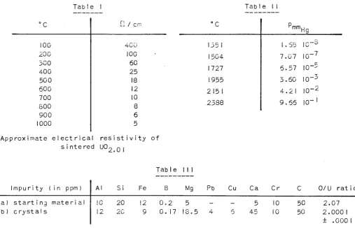
A c c o r d i n g t o T a b l e I t h e e l e c t r i c a l
r e s i s t a n c e o f
UO2 as a f u n c t i o n o f t h e t e m p e r a t u r e i s 5 Ω/cm at 1000°C [ 4 ] ' ; t h e c o n d u c t i v i t y at
t h i s t e m p e r a t u r e i s t h u s s u f f i c i e n t t o enable h e a t i n g by d i r e c t passage o f c u r r e n t .
The t u n g s t e n f o i l
is t h e r e f o r e m e l t e d by a s h o r t i n c r e a s e o f t h e c u r r e n t .
At this moment the temperature of the cylinder increases very fast to
± I550°C as measured on the outer wall by an optical pyrometer. An important
temperature difference between outer and inner wall of the cylinder will evidently
be originated. Since the outer wall cools more rapidly by radiation than the inner
wall, the temperature and thus the electrical conductivity of the inner wall will
soon be superior to those of the outer wall. This causes an increased current flow
through the inner wall and a decreased flow through the outer wall. Owing to this
semiconductor effect, the inner temperature can reach 2300°C while the outer tem
perature amounts to I800°C only at the end of the preparation, thus maintaining
the mechanical stability of the cylinder. The cylinder now fulfils its double
funet ion ;
a) The function of container of the U0
2vapour : as listed in Table II one obtains
a
PUO2 of ± 3
mm(-|q
a t2300°C„ The U0
2of the inner wal I
very
rapidly vaporizes
and is deposited on the tungsten sheet which is slightly cooled by its supporting
thermal insulator. Since great amounts of heat have to be evacuated through this
sheet, its temperature is at most 100°C below that of the inner wall of the
cylinder. The cylinder extremities, where the wall is conical ly thinned, evaporate
first as proved by the shortening of the cylinder soon after the start ,
After a few minutes enough UO^ is condensated to make the cylinder vacuum tight.
Since the wall itself is vapour tight, the vacuum of the furnace is maintained ;
even when a thermal fissure occurs, this will be closed in less than a minute by
the deposited υθ
2. Almost no UO2 evaporates from the outer wall due to the low
temperature „
b) The function of heating element : in our case some 200 A at ί 10 V passes through
the cylinder under normal conditions. This electrical resistance is ideal to
generate the desired thermal effect „
In this situation we have a micro-oven consisting completely of υθ
2, wherein a
relatively high pressure of υθ
2vapour is built up. Contamination is almost
impossible and no technological difficulties were encountered to reach the
temperature wanted .
Towards the end of the preparation the cyI inder wal Is become rather thin .
At that moment a more rapid deformation of the cylinder under the electrode
pressure announces the end of the process. The electrical resistance also d e
creases due to the thinning of the wall,, The desired current (200 A) can then
only be reached by a higher voltage (15 V) and an arc might form inside the U 0
2vapour filled cylinder. The process should be shut off at this moment.
1,3,3. Results
A f t e r c o o l i n g , t h e c y l i n d e r and t h e d e p o s i t s a r e e x t r a c t e d as a w h o l e „
The c y l i n d e r w a l l i s c o m p l e t e l y r e c r y s t a I I i zed and t h e i n n e r w a l l i s c o v e r e d w i t h
-very
regular tetrahedrons of 0.1 to 0,5 mm,. On the conical ends of the original
cylinder one finds hemispherical deposits with their flat side against the tungsten
sheet and their spherical surface towards the interior,, These deposits weigh some
20 to 30 grams and are composed of a few crystals ;
very
seldom they are but one
crystal .,
A slight hit separates the crystals into individual single crystals .
The crystal boundaries might, however, be so tight that the crystals can only be
separated by sawing and cutting
The grown crystals are up to 15 mm long and weigh up to 7 g.. The total
weight of the crystals, longer than 4 mm obtained from a cylinder of 100 g, amounts
to 5 - 8 g .
1.4. Discussion
1.4.1, Method and arrangement
The arrangement described has some disadvantages which have to be
elimi-nated. The preheating by means of a foil under the cylinder causes irregular
heating which sometimes leads to fissures. In a new arrangement (see Fig. 4) the
preheating is carried out by means of a tungsten spiral fed separately .
Another disadvantage of the given method lies in the fact that the
deposits cool very suddenly at the end of the process, The preheating spiral is
not molten and can thus be used for after-heating. The thermal contact between the
electrodes and the deposits will also be disrupted, The moving electrode therefore
slides some 15 mm backwards allowing the pins @ by the action of the springs @ ,
to move the ZrÜ2 disc, with the deposit a few mm away from the extremities of the
electrodes. These arrangements permit a controlled cooling .
Due to the negative temperature coefficient of U0
2the cylinder heated by
direct current passage, constitutes a very divergent electrical system which is
therefore difficult to stabilize,, In the new arrangement the manual control was
replaced by an automatic stabilization, the current being stabilized by a dry
t hy rat ron
1.4.2. Growth mechanism
1,4,2.1. Structure of the deposit
We now c o n s i d e r t h e o b t a i n e d s u b l i m a t e s i n more d e t a i l , . F i g . 5 r e p r e s e n t s
a s u b l i m a t e as o b t a i n e d . The g r o w t h s u r f a c e i s v e r y s h i n y and t h e g r a i n b o u n d a r i e s
a r e c l e a r l y m a r k e d . D u r i n g t h e e a r l y phase o f t h i s i n v e s t i g a t i o n s u r f a c e f e a t u r e s
w e r e o b s e r v e d whose o r i g i n was not i m m e d i a t e l y u n d e r s t o o d [ 5 ] . C h e m i c a l a n a l y s i s
showed a r a t h e r i m p o r t a n t i m p u r i t y c o n t e n t o f t a n t a l u m , , By c o n d e n s i n g on a t u n g s t e n
s h e e t t h e c o n t a m i n a t i o n as w e l l as t h e a s s o c i a t e d f e a t u r e s d i s a p p e a r e d ,
-The f l a t s u r f a c e o f t h e d e p o s i t , l y i n g a g a i n s t t h e condensation s h e e t ,
i s a p o l y c r y s t a l I i ne l a y e r . On t h i s l a y e r one f i n d s an area o f columnar c r y s t a l s
d e v e l o p i n g towards t h e growth s u r f a c e . The t h i c k n e s s o f t h i s area is at most
one mm in the c e n t r a l p a r t o f t h e s u b - l a y e r and up t o 5 mm at t h e edges „ Some o f
t h e columnar c r y s t a l s grow and become t h e large c r y s t a l s o f t h e d e p o s i t . They
usual ly have a
very
smal I base and grow l a r g e r towards t h e growth s u r f a c e .
2.4.2.2.
Mechanism
All deposits have their <l||> direction perpendicular to the base, the
maximum deviation being a few degrees . Large crystals often show the development
of a smal I <l||> facet observed as a c i re I e on the spherical growth surface.
Obviously, the large crystals grow according to a double mechanism :
(a) A polyerystal I i ne layer is first deposited on the cold condensation sheet ;
with increasing temperature it acquires a certain orientation resulting in
growth of columnar crystals . Only a few of these crystals will develop, in
particular these whose slowest growth direction is perpendicular to the
con-densation area, hampering the development of the other crystals by their latera!
g rowt h .
(b) The other mechanism is the growth by grain boundary migration . The form of
the deposits proves that the temperature at the central part of the deposits
is lower than at the edges . Indeed, the contact resistance of the cylinder
walls causes a strong local heating on the condensation sheet , Due to this
effect, a radial thermal gradient exists in the deposit and the grain boundaries
will migrate under the influence of the thermal stresses . Two supplementary
observations confirm this : Fig. 6 shows a grain boundary ; the original position
of the grain boundary, which has migrated, is clearly visible „ Another
indi-cation was found during the attempts to prepare crystals doped with a controlled
amount of A l
20
3and Nb
20c . Before pressing some 500 ppm of these oxide:s were
added to the U 0
2powder .
These experiments proved that it is impossible to grow large crystals by
this method , Some crystals of more than 4 mm were obtained but they had no more
than 150 ppm impurity content . The impurities evidently segregate towards the
grain boundaries and prevent their migration . By hindering the migration of the
grain boundaries the development of the crystals is limited to slightly enlarged
columns with a maximum diameter of 4 mm „
2.4.2.3.
Chemical purity
Chemical analysis proved that almost no impurities are introduced during
the process. In Table III the speet rographi c analysis of the starting material is
compared with this of the obtained crystal . Considering the less accurate results
of the analysis, we conclude that no impurities are introduced . A special analysis
showed 16 ppm of W in individual crystals ; the polycrystal I i ne ^ayer contained 350
ppm of W „
-The 0 / U r a t i o has been d e t e r m i n e d by means o f P o l a r o g r a p h i e m e a s u r e m e n t s
o f U i n a p h o s p h o r i c a c i d med i urn ; by d e v e l o p i n g t h i s method up t o t h e e x t r e m e
l i m i t s o f a c c u r a c y , t h e 0 / U r a t i o was f o u n d t o be 2 . 0 0 0 1 . As f o r t h e s t o i c h i o m e
t r i c c o m p o s i t i o n no d i s c r e p a n c y c o u l d be f o u n d by l a t t i c e p a r a m e t e r m e a s u r e m e n t .
2.4.2.4.
Physical perfection
Laue d i f f ractograms proved that the crystals have no mi sor i entat i on as
shown in the reflection image of Fig, 7 . Electron microscopy proved that large
areas exist without dislocations in spite of the fact that at the end of the process
the crystals were quenched by a temperature drop from 2300° C to I000°C in plus minus
one minute . In order to obtain starting material for the study of dislocations,
the crystals have to be deformed mechanically .
It was also possible to cleave the crystals, principally along the [ill]
plane but also along the [Ι ΙΟ] plane.
1.5. Conclusion
The given method which can undoubtedly be applied for the preparation
of single crystals of other materials than U0~, has proved to be reproducible,
unexpensive and simple ; single crystals of excellent chemical and physical
qualities of more than 10 mm size can be obtained which are suited for almost al
[image:14.595.31.539.447.773.2]physical measurements on U0
-, .
Table I
Table II
°C 100 200 300 400 500 600 700 800 900 1000
Ω / cm
40 ϋ 100 50 25 18 12 10 8 6 5 °C 1351 1504 1727 1955 215 1 2388
P m mHg
1.55 IC~S
7 . 0 7 I 0- 7
5 . 5 7 I O- 5
3 . 6 0 I O- 3
4 . 2 1 I O- 2
9 . 5 5 I O- 1
Approximate electrical resistivity of
s¡nte red U 0
2η |
Table M l
Impu r i t y ( i n ppm)
a) s t a r t i n g m a t e r i a l b) c r y s t a l s
A! 10 12 Si 20 20 Fe 12 9 B
0 . 2 0 . 17
Mg
5 1 8 . 5
Pb 4 Cu — 5 Ca 5 45 C r 10 10
c
50 500 / U r a t i o
2 . 0 7 2 . 0 0 0 1 ± . 0 0 0 1
References
[ l ] R.G. ROBINS, J . Nuc I . M a t . 3 , 2 9 4 ( 1 9 6 1 )
[ 2 ] R. COLOMBO, J . N u c l . M a t . 5, 259 ( 1962)
[ 3 ] BMI R e p o r t s r e l a t i n g t o c i v i l i a n a p p l i c a t i o n s I 9 6 0 , 1 9 6 1 , 1962
[ 4 ] DEG R e p o r t 120 ( R)
[ 5 ] W. VAN LIERDE, R. STRUMANE, E. SMETS and S. AMELINCKX, J . N u c l . M a t . 5 , 250
( 1 9 6 2 ) .
THE PREPARATION OF U 0
gSINGLE CRYSTALS FROM A MOLTEN SALT SOLUTION
OF URANYL CHLORIDE
2 . 1 . I n t r o d u c t i o n
T h i s r e p o r t d e s c r i b e s t h e s t u d i e s in t h e p r e p a r a t i o n o f u r a n i u m d i o x i d e
s i n g l e c r y s t a l s f r o m m o l t e n s a l t s o l u t i o n .
I t was f o u n d by HAMPE [ i ] i n 1888 t h a t U 02 c o u l d be p r o d u c e d by e l e c t r o
-l y s i s o f a m o -l t e n u r a n y -l c h -l o r i d e s o -l u t i o n .
GIBSON and WASSELL [ 2 ] a l s o i n v e s t i g a t e d t h e e l e c t r o - d e p o s i t i o n o f u r a n i u m d i o x i d e f r o m s o l u t i o n s o f u r a n y l c h l o r i d e i n f u s e d a l k a l i m e t a l h a l i d e m e l t s u s i n g c a r b o n e l e c t r o d e s . The e l e c t r o l y t i c U02 o b t a i n e d was s u i t a b l e e i t h e r as o x i d e p a r t i c l e s o f t h e c o r r e c t s i z e f o r d i s p e r s i o n t y p e f u e l s , o r f o r c o n s o l i d a t i o n by s w a
-g i n -g t e c h n i q u e s . The same p r o c e s s was s t u d i e d by LYON and VOYLAND [ 3 ] . The m a t e r i a l o b t a i n e d had p h y s i c a l p r o p e r t i e s w h i c h make i t p o t e n t i a l l y u s e f u l as a c e r a m i c f u e l m a t e r i a I .
The p i l o t p l a n t p r o d u c t i o n o f e l e c t r o l y t i c u r a n i u m d i o x i d e was a l s o i n
-v e s t i g a t e d by CHALKLEY [ 4 ] . The p r o c e s s has been f o u n d c a p a b l e o f p r o d u c i n g o x i d e s
w i t h i n t h e r a n g e o f c o m p o s i t i o n U 02 t o U 02 ^ .
I t was ROBINS [ 5 ] who f i r s t d e c i d e d t o use t h i s p r o c e s s t o o b t a i n s i n g l e c r y s t a l s on t h e c a t h o d e s u r f a c e . We c o n s i d e r e d i t w o r t h w h i l e t o t a k e up ROBINS's
method i n o r d e r t o i n v e s t i g a t e t h e p o s s i b i l i t y o f o b t a i n i n g l a r g e U 02 s i n g l e c r y s -t a l s s u i -t a b l e f o r a v a r i e -t y o f p h y s i c a l m e a s u r e m e n -t s .
I t was a d m i t t e d t h a t u n d e r p a r t i c u l a r c o n d i t i o n s o f c a t h o d e c u r r e n t d e n s i t y , a p p l i e d p o t e n t i a l and t e m p e r a t u r e o f o p e r a t i o n s e p a r a t e s i n g l e c r y s t a l s
can be o b t a i n e d on t h e c a t h o d e s u r f a c e .
2 . 2 .
E x p e r i m e n t a l
2.2,1.
Apparatus
As i n R O B I N S ' s e x p e r i m e n t s , t h e e l e c t r o l y s i s c e l l c o n s i s t s o f a r o u n d b o t
t o m e d v i t r e o u s s i I i c a t u b e 5 cm b o r e χ 25 cm l o n g , w h i c h c o n t a i n s 6 0 0 g o f m e l t .
The c e l l i s f i t t e d w i t h f o u r h o l e s t o a c c o m m o d a t e t w o e l e c t r o d e s , a v i t r e o u s s i l i c a
t h e r m o c o u p l e p o c k e t and an a r g o n i n l e t t u b e ( s e e F i g . 8 ) .
The c a t h o d e c o n s i s t s o f a p l a t i n u m s h e e t 2 cm χ 4 cm χ 0 . I mm. i t i s
c o n n e c t e d t o a p i a t i n urn w i r e , p r o t e c t e d by a v i t r e o u s s i I i c a cap i I I a r y . The anode
i s a h i g h p u r i t y g r a p h i t e rod 5 mm d i a m e t e r χ 30 cm l o n g . A f u r n a c e o f 1.5 kW i s
used t o m e l t t h e s a l t . The t e m p e r a t u r e i s m e a s u r e d and c o n t r o l l e d by a F o s t e r r e g u
l a t o r .
The c i r c u i t u s e d i s shown i n F i g . 9 . A c o n s t a n t v o l t a g e i s s u p p l i e d by
a s t o r a g e b a t t e r y , i n s e r i e s w i t h a v a r i a b l e r e s i s t a n c e , t h e c e l l i t s e l f and an
a m m e t e r . D i r e c t r e a d i n g s a r e t a k e n f r o m t h i s a m m e t e r and t h e v o l t m e t e r c o n n e c t e d i n
p a r a l l e l w i t h t h e c e l l . The a p p l i e d p o t e n t i a l , c u r r e n t and t e m p e r a t u r e a r e r e c o r d e d
by a C a m b r i d g e r e c o r d e r .
To p r e v e n t a i r d i f f u s i o n i n t h e c e l l a s l i g h t o v e r p r e s s u r e o f a r g o n i s
m a i n t a i n e d i n t h e e e l I . To p u r i f y t h e a r g o n , t h e g a s f l o w s t h r o u g h t h r e e t u b e s c o n
t a i n i n g c a l c i u m c h l o r i d e , s i l i c a g e l and p h o s p h o r o u s p e n t o x i d e i n o r d e r t o a b s o r b
w a t e r v a p o u r , , I t t h e n f l o w s t h r o u g h one t u b e c o n t a i n i n g an a c t i v e Cu BTS c a t a l y s e r
o f t h e B a d i s c h e Anal i n & Soda F a b r i k i n o r d e r t o a b s o r b o x y g e n .
2.2„2.
Melt
preparation
The e u t e c t i c m i x t u r e o f NaCI K C l i s c h o s e n as s o l v e n t on a c c o u n t o f i t s
r e l a t i v e l y l o w m e l t i n g p o i n t ( 6 6 0 ° C ) and i t s a b i l i t y f o r d r y i n g . I n d e e d , i f m o i s
t u r e i s n o t r e m o v e d , h y d r o l y s i s o c c u r s as i n d i c a t e d by eq„ ( I ) .
/
C I " + H20 H CI + OH" ( I )
A r e c e n t m e t h o d d e v e l o p e d by MARICLE and HUME [ 4 ] c a n be used t o remove t h e h y d r o x i d e
i m p u r i t i e s . T h i s i s a c h i e v e d by p a s s i n g c h l o r i n e t h r o u g h t h e m e l t as s o o n as t h e
m e l t i n g p o i n t o f t h e u n d r i e d s a l t s i s r e a c h e d .
T h i s r e a c t i o n i s p r e s u m a b l y :
2 OH" + 2 CI 2 — 02 + 2 H C I + 2 C I " ( 2 )
The h y d r o x i d e i o n i s t h u s removed w i t h o u t c o n t a m i n a t i n g t h e m e l t by some e x t r a n e o u s
n o n v o l a t i l e s p e c i e s . The o x y g e n and h y d r o g e n c h l o r i d e g a s e s a r e s w e p t o u t o f t h e
c h l o r i n e . In a c c o r d a n c e w i t h MARICLE and HUME t h e h y d r o x i d e ¡on c o n c e n t r a t i o n i s
l o w e r e d b e l o w a l e v e l d e t e c t a b l e p o I a r o g r a p h i c a l l y a f t e r a b o u t 30 m i n u t e s o f t r e a t
ment w i t h c h l o r i n e .
- 8
U r a n y l c h l o r i d e i s p r e p a r e d by p a s s i n g c h l o r i n e t h r o u g h t h e s o d i u m -p o t a s s i u m c h l o r i d e m e l t i n w h i c h UO2 -powder has been s u s -p e n d e d . T h i s r e a c t i o n can
be w r i t t e n as
> 6 6 0 ° C
U00 + CI o * - U 00 Cl o ( 3 )
2 2 (NaCI - K C l ) 2 2
2.2.3. Electrolytic reduction of uranyl chloride
The s t a n d a r d p o t e n t i a l o f U 0 |+ ( V I ) - U 02 ( I V ) i n t h e L i C I - K C l e u t e c t i c
has been m e a s u r e d a t 450°C by H I L L e t a l . [ 7 ] „ The v a l u e o b t a i n e d by t h e s e a u t h o r s i s - 0 . 2 8 5 ± 0 . 0 0 5 v o l t a g a i n s t a s t a n d a r d P t ( I I ) - P t ( 0 ) r e f e r e n c e e l e c t r o d e .
T h i s v a l u e has been t a k e n as a r o u g h a p p r o x i m a t i o n i n o u r s y s t e m .
The e x p e c t e d r e a c t i o n s a r e
-»- U 0 t+ + 2 C I " I 4 )
uo
2ci
2U 02 + + 2 e · - U 02 ( 5 )
2 C I " · - CI 2 + 2 e ( 6 )
2.2.4. Procedure
A f t e r m e l t i n g t h e s a l t , c h l o r i n e i s i n j e c t e d i n t o t h e b o t t o m o f t h e c e l l
t h r o u g h a s i l i c a t u b e . The t e m p e r a t u r e i s i n c r e a s e d t o 8 4 0 ° C . A f t e r one h o u r o f c h l o r i n a t i o n p u r e UO2 powder i s added t o t h e m e l t . When t h e m e l t becomes r e d d i s h
-o r a n g e , t h e u r a n i u m -o x i d e i s c -o m p l e t e l y d i s s -o l v e d i n t h e s a l t . The e l e c t r -o d e a s s e m b l y i s t h e n i n t r o d u c e d . The e l e c t r o l y t i c c u r r e n t i s a d j u s t e d t o 50 mA, w h i c h
o
corresponds to a cathode current density of 4 mA/cm „ When the run is stopped the platinum cathode is cooled in air. The deposit is then carefully washed with dilute HCl, distilled water, acetone and ether.
2.2.5. Current density
ROBINS f o u n d t h a t t h e o p t i m u m c u r r e n t d e n s i t y must be s u c h t h a t U 02 c r y s
t a l s n u c l e a t e on t h e c a t h o d e s u r f a c e a t a mean d i s t a n c e o f a b o u t 5 mm . T h i s i s n e c e s s a r y i n o r d e r t o a v o i d c r o s s - o v e r g r o w t h , p a r t i c u l a r l y i f one w a n t s t o o b t a i n
l a r g e c r y s t a l s . The i n f l u e n c e o f c o n c e n t r a t i o n and c u r r e n t d e n s i t y a r e i n one way c o m p l e m e n t a r y . By i n c r e a s i n g t h e c o n c e n t r a t i o n a h i g h e r c u r r e n t d e n s i t y i s a l l o w e d b e f o r e t h e d e p o s i t i o n becomes s p o n g y .
A c c o r d i n g t o GLAZUN0V [ δ ] t h e i n c r e a s e o f t h e c o n c e n t r a t i o n s h o u l d r e s u l t
i n an i n c r e a s e o f t h e c r y s t a l s i z e i n t h e d i r e c t i o n p a r a l l e l t o t h e c a t h o d e s u r f a c e and i n a d e c r e a s e i n t h e d i r e c t i o n p e r p e n d i c u l a r t o i t .
2.2.6. Polishing experiments of the cathode surface
A f t e r each e l e c t r o l y s i s e x p e r i m e n t i t has been f o u n d n e c e s s a r y t o p o l i s h t h e p l a t i n u m f o i l a g a i n . M e c h a n i c a l , e l e c t r o l y t i c and c h e m i c a l m e t h o d s were t r i e d .
E l e c t r o p o I i s h i n g o f t h e p l a t i n u m f o i l s was p e r f o r m e d u n d e r t h e f o l l o w i n g
c o n d i t i o n s :
e l e c t r o l y t e : s o d i u m c h l o r i d e , p o t a s s i u m c h l o r i d e o r sod i urn c h l o r i d e p o
t a s s i u m c h l o r i d e e u t e c t i c c o m p o s i t i o n ,
t e m p e r a t u r e : 1000°C
c u r r e n t d e n s i t y : 15 mA/cm^„
M e c h a n i c a l p o l i s h i n g w i t h a d i a m o n d p a s t e g a v e b e t t e r r e s u l t s and p e r m i t s
t o use t h e p l a t i n u m f o i l s i n more t h a n f i v e r u n s .
2.2,7.
Anode
material
In one e l e c t r o l y s i s we r e p l a c e d t h e c a r b o n a n o d e by a s i n t e r e d u r a n i u m
o x i d e rod ( 6 mm d i a m e t e r x 100 mm l o n g ) „
The e l e c t r o l y s i s was c a r r i e d o u t w i t h t h e m e l t open t o t h e a i r and w i t h
a c u r r e n t d e n s i t y o f 4 m A / c m-2 z „ The d e p o s i t c o n s i s t e d o f f i n e c r y s t a l s o f U^Og .
2 . 3 .
D i s c u s s i o n
P r e l i m i n a r y e x p e r i m e n t s show t h a t i t i s p o s s i b l e t o d e p o s i t UO2 c r y s t a l s
b e l o w t h e a p p a r e n t d e c o m p o s i t i o n p o t e n t i a l o f U 0 Í i o n s . S m a l l c r y s t a l s o f UO2
h a v e a l s o been d e p o s i t e d on t h e c a r b o n a n o d e . In one e l e c t r o l y s i s e x p e r i m e n t we
o b t a i n e d on t h e c a t h o d e s u r f a c e c o l u m n a r c r y s t a l s o f UzOg .
WILKS [ 9 ] , who made a s t u d y o f t h i s p h e n o m e n o n , s u g g e s t s t h a t t w o s i m u l
t a n e o u s r e a c t i o n s o c c u r , n a m e l y a t h e r m a l d e c o m p o s i t i o n o f υ θ2Ο Ι2 '·
++
5 U 02C I2 : = = = £ ■ u308 ( C l 2 ) + 2 U 0 C I2 + 2 C I2 ( 7 )
and a r e a c t i o n w i t h t h e c a r b o n a n o d e
6 U 02C I2 + 3 C · , » ■ 2 U C I4 + 3 U 02 + U 0 C I2 + 2 C 02 + CO + C 12 ( 8 )
The U C I 4 p r o d u c e d , r e a c t s w i t h t h e U 02 and t h e U30 g C I2 as i n d i c a t e d by e q . ( 9 ) and
( 1 0 ) „
U 02 + U C I4 . , — . 2 U 0 C I2 ( 9 )
U C I4 + U30 g C I2 Z ^ ^ T 4 U02CI + C l2 ( |0 )
The U02CI p r o d u c e d d u r i n g t h e s e r e a c t i o n s i s t h e n r e d u c e d e I e e t r o l y t i c a l l y as
f o I Iows
U02CI . U 02 + I / 2 C 12 ( I I )
2 U 02 + + 2 e »2 U 02 ( 1 2 )
2 C I " 2 e fc.CU ( | 3 )
I f UCI4 i s n o t s u f f i c i e n t l y f o r m e d by r e a c t i o n ( 8 ) , a l l U30 g+ + i o n s a r e
n o t removed and t h e U-*Og++ i o n s a r e t o g e t h e r w i t h U 02 + i o n s deposed at t h e p l a t i n u m
c a t h o d e . To p r o d u c e UO2 c r y s t a l s , t h e c a r b o n r o d i s d i p p e d 5 cm i n t h e m e l t .
A l l e x p e r i m e n t a l o b s e r v a t i o n s a r e e x p l a i n e d by t h i s r e a c t i o n m e c h a n i s m .
2 . 4 . C o n c l u s i o n
I t i s c o n c l u d e d t h a t ROBINS's m e t h o d i s o n l y s u i t a b l e t o o b t a i n r e l a t i v e l y s m a l l c r y s t a l s ; t h e r e a l s o l u t i o n t o t h e p r o b l e m o f m a k i n g l a r g e r s i n g l e c r y s t a l s
seems t h e r e f o r e t o be t h e s u b l i m a t i o n method d e s c r i b e d i n s e c t i o n I .
The a v e r a g e s i z e o f UO2 c r y s t a l s o b t a i n e d on t h e c a t h o d e was I mm.
F i g . 10 shows a m a c r o - p h o t o o f t h e d e p o s i t on t h e p l a t i n u m c a t h o d e . F i g . I I and 12
show t h e s t r u c t u r e s u r f a c e o f t h e c r y s t a l s . The r u n s were p e r f o r m e d u n d e r t h e f o I
-Iowi ng cond i t i o n s :
- t e m p e r a t u r e : 840°C
- a p p l i e d p o t e n t i a l : 100 - 150 mV
- c a t h o d e c u r r e n t d e n s i t y : 4 mA/cm
- U 02C I2 c o n c e n t r a t i o n : 15 g U 02C I2 / 600 g NaCI - KCl
- e l e c t r o l y s i s t i m e : 20 h o u r s
- t o t a l v o l u m e o f m e l t : 600 g NaCI - KCl
- t h e m a j o r i t y i m p u r i t i e s w e r e p o t a s s i u m and sod i urn : 100 ppm.
R e f e r e n c e s
[ l ] HAMPE W„, Chem. Z t g . \2, 106 ( 1888)
[ 2 ] GIBSON A . R . and WASSELL L . , U.K. 19 ( 1959)
[ 3 ] LYON W . L . and V0YLAND E . E . , H.W. - 6 2 . 4 3 1 ( 1 9 5 9 )
[ 4 ] CHALKLEY J . R . , J . Less Common M e t . 3 , 2 ( 1 9 6 1 )
[ 5 ] ROBINS R . G . , A . E . R . E . - R.3506 ( I 9 6 0 )
[ 6 ] MARICLE D . L . and HUME D . N . , J . E l e c t r o c h e m . Soc. 107, 4 ( I 9 6 0 )
[ 7 ] H I L L D . L . , PERAN0 J . and OSTERYOUNG R . A . , J . E l e c t r o c h e m . Soc. _I07, 702 ( I 9 6 0 )
[ 8 ] GLAZUN0V Ζ . , P h y s . Chem. 167. 399 ( 1 9 3 4 )
[ 9 ] WILKS R . S . , A . E . R . E . - R.3833 ( 1 9 6 1 ) .
1. water inlet
2. water outlet
3. e lectrode
4·.
sight glass
5. water cooled flange
6. clamp
7. ZrOz slice
8.
power leads
9. electrode
10. comparator
11. tombac
12. silica tube
13. U0
2cylinder
Ut. gaskets
15. shield
Θ Θ ©
©Θ Θ
Fig. 1
1. wattr cooling
2.electrode
3. tungsten sheet
A. tantalum sheet
5. U0
2cylinder
6. ZrOi
.
7. clamp
's;;;;;;;j;/;;j;;;;;;j
^ww^wwwv^
Fig. 2
φ
23*1
Fig. 3
1. water
cooling
2.
electrode
3.
spring
4.
pin
5. clamp
6. tantalum
sheet
7. ZrO
z8. tungsten
sheet
9. UOQ
cylinder
10. wire
11. spring
T2. electrode
φ
φφ
φφ®φ@φ
φ
φ
©
? > > ' .-■
C/194/63
Fig. 5
Fig. 6
■
•
*
τ
r ' f > f > ^ f > j
ι
. ' ν · , ι \
. 1 «
r \#
ι Ι
Τ
^
Silica tub· 1ο protect
th· thtrmocoupl·
Platinum wir·
^Ί
\• > > > > * > > ' *·
Graphit· anod·
Argon in Igt
1 , * *■
■
I
. ' . · ■
,« ' ' .
' v I
t Ζ / ? 2
Heating, w i r ·
Thermal isolation
Melt
Platinum sheet
Firebrick
Ill
Λ / V W V
t
Fig. 10
Fig. 11
Fig. 12
'F
l' ill·.*.!