Structural and Earthquake Engineering Applications of a
Model Wooden Structure
Ayse Elif Özsoy, Hasan Özkaynak
*Faculty of Engineering and Architecture, Civil Engineering Department, Beykent University, Turkey
Copyright©2017 by authors, all rights reserved. Authors agree that this article remains permanently open access under the terms of the Creative Commons Attribution License 4.0 International License
Abstract In this study, small scale “hands-on”
experiments were conducted on a model wooden frame structure under dynamic effects. The base excitation was applied to the specimen by a “home-made” shaking table which was designed and developed within the scope of the graduation projects of civil engineering students. The device is capable of producing harmonic motion at the base level of the model structure. Two alternative structural systems were designed and constructed namely rigid frame and flexible frame. Displacement responses derived from the tests were compared with the linear time history analysis. The analytical model is capable of capturing the achieved displacement values. In the second part of the study, harmonic tests were performed on the frame structure which was instrumented with small scaled seismic isolation devices. Seismic isolators were selected as pendulum bearings which are installed between the structure and its foundation in order to isolate the supported structure from harmonic excitations. Design of structures with the friction pendulum technology is cost-effective, since the isolated structure behaves elastically during the seismic motions without any structural damage. The base isolation device having the characteristics of a pendulum tends to increase the natural vibration period of the isolated structure with the reduced dynamic forces. The test results showed that displacement and the acceleration responses of the isolated structure were significantly reduced.Keywords
Balsa Wood, Shake Table Seismic Isolation, Energy Dissipation, Structural Dynamics1. Introduction
Structural engineers are responsible to design and to construct earthquake resistant structures by the use of latest design techniques and technologies. Understanding how the structures behave under dynamic loads is important for civil engineering students to improve their engineering skills for the seismic design. Main design concepts of structural and
earthquake engineering applications such as vibration modes, time history analysis and structural damping can be explained by performing “hands-on” experiments to the civil engineer candidates. Energy dissipation systems are among the latest technologies for the earthquake resistant design and retrofitting. Seismic isolation is an innovative earthquake protection system which is installed in between the structure and its foundation. The isolated structure responds elastically under seismic motion hence the seismic isolation device tends to reduce the structural damage. Small scale dynamic tests on model structural models are quite practical to simulate the dynamic effects to the structures. Moreover it is possible to derive some important results related with the dynamic behavior of the seismically isolated structure. There are many techniques for seismic isolation of the structures such as lead rubber bearing, high damping bearing and friction pendulum bearings. The idea of the friction pendulum bearings is to enforce the foundation of the structure to dissipate the input earthquake energy by the friction mechanism taking place in between two similar shaped steel concave surfaces [1].
bearing [3].
Figure 1. Production of the friction pendulum bearing [4, 5]
The size of the structure, axial loads to be transferred to the foundation and the underlying soil conditions are the key parameters for the decision of the physical and mechanical properties of the sliding pendulum bearings. In this content, the design of the isolated structure and the isolator itself mainly depend on experimental results to be derived from the real scale specimens. The target displacement demand of the structure could be adjusted
according to the radius and curvature of the sliding bearing. The friction occurring along the surface of the bearing system enables the structure to stay in the elastic range without having any structural damage, besides it supplies a significant amount of damping to the structure. The energy transmitted to the structure is mainly prevented by the isolating system. The second order affects are eliminated through the use of sliding pendulum bearings since, the curvature of the surface causes the structure to re-center to its original position. Identifying the effects of a small scale single pendulum bearing as an isolation system on the dynamic behavior of a model structure is one of the objectives of this study.
[image:2.595.57.302.85.637.2]2. Materials and Methods
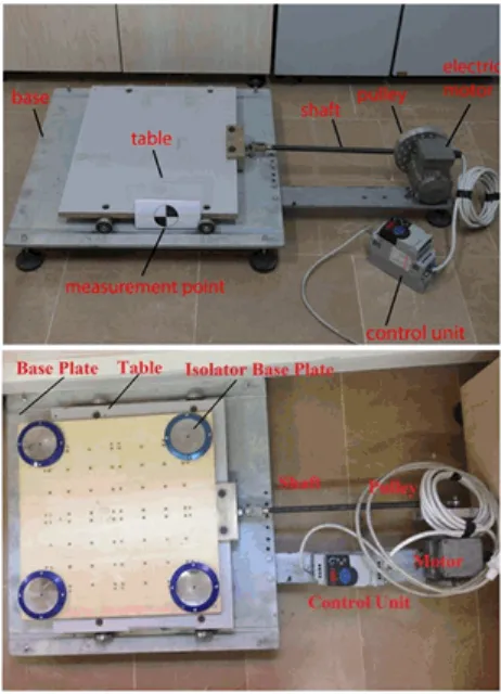
[image:3.595.63.294.320.640.2]The experiments conducted by using shaking table facilities and their serviceability costs are quite expensive in earthquake engineering. Especially the structures which are instrumented with energy dissipation technology devices such as seismic isolators need to be tested under dynamic effects. However, great efforts are needed to be performed by shaking table tests on non-scaled structures. In this study, an educational shaking table with a size 50×50 cm has been developed in order to perform forced vibration tests. The wooden table is free to move in the direction of the shaft and the motion in the perpendicular direction is restrained by the use of rollers. It is designed to support the model structure and to apply harmonic base excitation by an electrical motor which is controlled with a simple control system device (Figure 2). The isolated structures are fixed to a rigid plate, where the virgin specimen was fixed to the shaking table.
Figure 2. General scheme of the shaking table for the fixed based and isolated structure
The input vibration of the shake table is guided by electrical controlling device. The vibration tests were performed under representative sinusoidal motion with increasing frequencies (0-6 Hz.). The digital screen of the control device shows the excitation frequency which enables the user to apply the motion with constant
amplitudes during the experiments. The shaft which is assembled on the wooden table and the pulley is pin-jointed to avoid the bending moment on the transverse direction of motion. The rollers are fixed under the wooden table allowing it to move on heavy thick metal plate.
[image:3.595.313.553.453.719.2]Displacement response history of the test specimens were recorded by a mid-high speed camera capturing the photos of the circle images placed on desired locations of the structure. The response has been determined in two main phases. In the first phase, the motion of the test specimen during the vibration test was recorded by a mid-high speed camera capturing images of the circles placed on specific locations of the structure. The digital camera used in this study was capable of capturing 50 pictures per second (Figure 3). In the second phase, the images were processed by software specially developed in MATLAB [12]. The amount of data collected might be increased by higher speedy cameras. The exact position of the reference points has been processed to determine the center coordinates and the radius of the circle from the scanned images. The displacement response in the time domain depends on the distance of the camera from the image. Thus, the visual data has been scaled to metric system to assess and identify the optimum distance for the image to be recorded by the camera. This technique has the advantage of the low cost, easy to be used and the accuracy of the measured data. The acceleration time history of the vibration tests were derived from the displacement response of bottom and top height of the model structure by using Central Difference Method [13] for time integration.
3. Specifications of the Model
Specimens
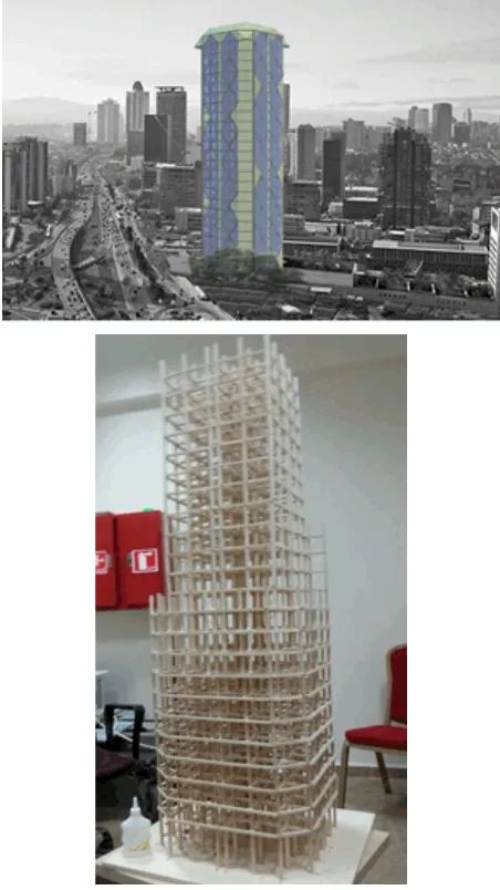
[image:4.595.64.290.331.733.2]The model structure is made up of balsa wood which is very light in weight. The plan dimensions are 361 × 361 mm with hexagonal shape. Due to the symmetry in plan, the center of the rigidity and the center of the gravity almost intersect at the same point. The rendered model and corresponding scaled wooden structure are illustrated in Figure 4. The story height of the scaled structure is 50 mm and the total height is 1250 mm.
The weight of the frame with the additional masses mounted at each 3 storey is 1.375 kg. The cross sections of balsa wood sticks representing columns and beams have the dimensions of 6×6 mm. During the construction, high tensile strength glue has been used to provide rigid connection between beams and columns. The columns at the base are directly fixed inside the connection holes drilled on the base plate. With this technique, the balsa wood frame models satisfy the fully fixed support condition at the base level.
Figure 4. General view of the model structure and construction of the frame
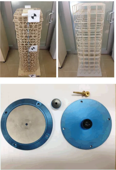
The experimental program for earthquake application consists of testing the specimens with and without base isolation. The fully fixed frames referring to the specimens without base isolation (FA1 and FB1) have the same plan area and total height but different lateral stiffness as shown in Figure 5 and 6. Two balsa wood frame models have been designed with alternative structural systems in terms of ductility level. Frame A with shorter spans and bracings at the façades represents a rigid structure whereas Frame B is a flexible structure with larger span lengths and story height. The general view of the single pendulum bearing is shown in Figure 6. The diameter of the pendulum is 12 cm and the thickness is 2.5 cm. The configuration and the geometric properties of the test specimens are summarized in Table 1.
4. Structural and Earthquake
Engineering Applications
4.1. Structural Engineering Applications
The acceleration time history for the tests performed for the structural application has derived from the displacement response of bottom, mid-height and top of the model structure by using Central Difference Method [13] for time integration. The input motion is determined by digitizing the motion of the point at the bottom of the model structure. The input acceleration record is given in Figure 7. The peak acceleration is determined as 1.08 m/s2 within the 25 seconds duration of vibration test.
The reference points are identified as the three critical points in order to capture the lateral deformed shape of the test specimen. The displacement response of the structure is derived from the data extracted from the top and bottom level of the specimen, Figure 8.
[image:4.595.324.545.513.730.2]Frame B
Figure 5. Plan view of the model structures
Figure 6. General view of rigid and flexible model structures and implemented scaled isolator
-0.20 -0.15 -0.10 -0.05 0.00 0.05 0.10 0.15 0.20
0 2.5 5 7.5 10 12.5 15 17.5 20 22.5 25
A
ccel
ar
at
io
n (
g)
Time (s)
Figure 7. The input acceleration record
-50 -40 -30 -20 -10 0 10 20 30 40 50
15 17.5 20
D
is
pl
acem
en
t (
m
m
)
Time (s)
[image:5.595.72.292.82.335.2]Top Bottom
Figure 8. The displacement response of the model structure from the top and bottom levels
[image:5.595.58.296.358.707.2] [image:5.595.323.545.521.729.2]Table 1. General specifications of model structures.
Description of the model Description of the test
Frame A
Rigid structural system Total height: 1250 mm Number of stories: 24
Span length of the beams: 57 mm Height of the columns: 50 mm Fundamental period of FA1: 0.09 sec
FA1: Rigid structure without base isolator.
Frame A is directly fixed to the base plate on the shake table.
FA2: Frame A is supported by a set of the friction pendulums that are fixed to the base plate of the shaking device.
Rigid structure with base isolator.
Frame B
Flexible structural system Total height: 1250 mm Number of stories: 12
Span length of the beams: 85 mm Height of the columns: 100 mm Fundamental period of FB1: 0.24 sec
FB1: Flexible structure without base isolator.
Frame B is directly fixed to the base plate of the shaking device.
FB2: Flexible structure with base isolator.
Frame B is supported by a set of the friction pendulums that are fixed to the base plate of the shaking device.
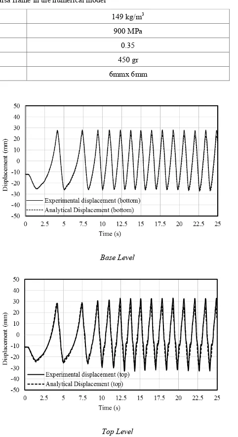
Table 2. Material properties of the balsa frame in the numerical model
Mass per Unit Volume 149 kg/m3
Modulus of Elasticity 900 MPa
Poisson’s Ratio 0.35
Additional Masses at the Storey Levels 450 gr
Dimensions of the Balsa Frame Elements 6mmx 6mm
The displacement responses recorded at top and bottom levels clearly indicates that the lateral deformation along the height of the frame is quite small. The acceleration time history derived from the top, mid-height and the bottom of the specimen have nearly the same values. Hence, the specimen has a rigid body motion under the input base excitation. However the difference between the top and bottom levels of the specimen can be observed when the response is zoomed in between 15 to 20 seconds, Figure 8.
The verification of the experimental results were done with the analytical model of the scaled balsa frame which was developed SAP 2000 [11]. The mathematical and 3D rendering architectural models for the structural system are illustrated in Figure 9. The fixed based fundamental periods of Frame A and B are obtained by modal analysis and determined as 0.09 and 0.24 seconds, respectively. Since the geometry of the model structures is symmetrical with respect to the orthogonal axes, the center of rigidity coincides with the center of gravity which is the geometric center point of the plan [11].
Linear time history analysis has been performed using the acceleration record that is obtained from the base of the specimen as the input motion. The material properties used for the analytical modeling of the small scale specimens are given in Table 2.
Figure 10 shows the displacement time history at the top and the bottom levels obtained from the experimental study and the analytical model for the study conducted within the scope of structural engineering applications. The figure clearly reveals that the experimental and the analytical results are in good agreement.
Base Level
Top Level
[image:6.595.313.554.238.680.2]4.2. Earthquake Engineering Applications
In this part of the study, vibration tests were performed in order to assess the effect of small scale base isolation system on the dynamic behavior of the scaled model structures. The specimens constructed for the experimental study have been designed to represent two types of structural system namely as the rigid and the flexible structure. Frame B referring to the flexible structure has a natural period of T1=0.24 seconds which is approximately three times larger than that of the rigid one called Frame A (T1=0.09 seconds) obtained by modal analysis of the fixed based analytical model of the structures. The balsa wood frames have been tested under the horizontal harmonic base motion with increasing excitation frequencies.
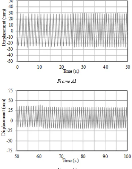
The displacements were measured from the bottom and top for the specimens. The top displacement values of the frames without isolators are illustrated in Figure 11. The response derived from test results indicates that the flexible frame has a higher lateral deformation in comparison with the rigid frame as it would be expected. On the other hand, the zero crossing length in the time axis is higher than the rigid frame which shows that the fundamental period of the flexible Frame B1 is greater than the rigid Frame A1.It should be noted that there is a significant reduction in the lateral deformations for the isolated structures under the vibration tests.
The horizontal displacement observed from the flexible specimen was higher than that of the rigid frame. The effect of the base isolators has started beyond a certain level of excitation frequency. The isolators were capable to re-center the complete specimen to nearly its original position. The relative displacement of the top story for each structural system has been reduced when they were equipped with the base isolators. Hence, the superstructure of each test specimen was subjected to a rigid body motion due to the isolation effect. The maximum roof displacements derived from the test results of Frame A1 and B1 are 29 mm and 33.5 mm, respectively. The results from the systems without base isolation reveal that the flexible structure, Frame B1 has a 15% higher displacement demand in comparison with the rigid frame (Frame A1).
Frame A1
Frame B1
Figure 11. The displacement response at the top level of rigid and flexible fixed based frames
[image:7.595.319.547.78.220.2]The lateral displacement of the base isolator of rigid frame was significantly higher than the isolator used for the flexible structure. The difference in the displacements measured from the base of the frame and from the shake table corresponds to the displacement demand of isolator during the motion. Vibration tests performed on both the rigid and the flexible frames gives a clear idea for the effect of the scaled isolators on the dynamic behavior of the structures.
Figure 12 shows the comparison of the top displacement response for the rigid structure with and without base isolation (Frame A1 and A2). It is observed that there is a reduction in the horizontal displacement amplitude at top level from 29 mm (Frame A1) to 25 mm (Frame A2). Thus, the frame with base isolation has a decrease in the displacement response.
Frame A1
Frame A2
Figure 12. The displacement response at the top level of rigid frames without and with base isolation
[image:7.595.320.541.435.718.2] [image:7.595.64.291.598.735.2]with and without isolator system, it can be concluded that base isolation with single pendulum causes a significant decrease in the lateral displacement values of the structure. In the case of corresponding real structures under seismic excitation, isolation systems tend to decrease the earthquake demand of the structure. Eventually, the internal forces will significantly decrease which will help the structure to withstand credible earthquakes.
5. Conclusions
The earthquake resistant design of structures requires understanding the structural response and especially the dynamic behavior under the effects of seismic loads. Seismic isolation is an efficient system providing passive control of structures. Among the energy dissipation systems, application of base isolation is an innovative technique for the seismic protection of the buildings. Small scale vibration tests are cost efficient and practical to simulate harmonic loading and to discuss the effects of isolation systems on small scale structures. This study presents an outstanding research on the structural behavior of the small-scale balsa wood frames under vibration tests. In this content, a small-scale shaking table have been designed and developed. The device was capable of vibrating the model models under a harmonic base motion. Furthermore, the dynamic response of the isolated structures has been examined by the implementation of the small scale friction pendulum as a base isolation device. For the isolated structures, the test results reveal that the contribution of the isolation system to the dynamic performance depends on the structural system as well as the frequency content of the input base motion.
Acknowledgements
Mrs. Mehtap Tuncer KARAOSMANOĞLU from MAURER Torbali Genleşme Derzleri San Ve Tic Ltd Şti, Msc. Civil Engineers Mehmet ŞENTÜRK and Merve ÇAĞLAR are gratefully acknowledged for their support.
REFERENCES
[1] Kravchuk, N., Colquhoun, R. and Porbaha, A. 2008. Development of a Friction Pendulum Bearing Base Isolation System for Earthquake Engineering Education. American Society for Engineering Education Pacific Southwest Annual Conference, Sacramento, CA, USA.
[2] Petti, L., Giannattasio, G., De Iuliis, M. 2008. Small Scale Experimental Testing To Verify The Effectiveness Of The Base Isolation And Tuned Mass Dampers Combined Control Strategy. The 14th World Conference on Earthquake
Engineering, Beijing, China.
[3] MAURER AG, Online available from http://www.maurer.eu/ [4] Friction pendulum bearing, Online available from
http://www.earthquakeprotectionsystem.com
[5] Friction pendulum bearing, Online available from http://www.alga.it
[6] S.J. Dyke, S.M. Johnson, R.T. Ranf, J.M. Caicedo, and M. Soto-Fourier, 2002. Advancing Earthquake Engineering Education though a Cooperative Effort Based on Instructional Shake Table, Proceedings of the 7th US National Conference
on Earthquake Engineering, EERI, Boston, Massachusetts, USA.
[7] Kukreti, A.R. and Wallace, B.J., 1996. Teaching Dynamic Behavior of Structures Using Small-Scale Structural Dynamics Laboratory, Proc. of the 31st Midwest Section
ASEE Conference, Tulsa, Oklahoma, Japan.
[8] Dyke, S.J., 1997. Experiences in Integrating Research and Education After the Engineering Education Scholars Workshop, Proc. of the ASEE Frontiers in Education Conf., Pittsburgh, PA, USA.
[9] Dyke, S.J., Truman, K.Z. and Gould, P.L., 2000. Current Directions in Earthquake Engineering Education: The University Consortium on Instructional Shake Tables, Proc. of the ASEE Annual Meeting, St. Louis, MO, USA.
[10] Dyke, S.J., Nepote, B., Caicedo, J.M., Johnson, S.J. and Oware, E., 2000. Earthquake Engineering Education: A Modern Approach, Proc. of the ASEE Annual Meeting, St. Louis, Missouri, USA.
[11] Computers and Structures. 2010; Inc., CSI Analysis Reference Manual for SAP2000, ETABS and SAFE, Computer and Structures, Inc., Berkley, California, USA. [12] MathWorks Inc. 2009. Matlab 7 Getting Started Guide, The
MathWorks Inc., Natick, MA, USA.
![Figure 1. Production of the friction pendulum bearing [4, 5]](https://thumb-us.123doks.com/thumbv2/123dok_us/8748996.891466/2.595.57.302.85.637/figure-production-friction-pendulum-bearing.webp)