THD Reduction Using Shunt Active Power Filter: A Real
Case Study
Lina Alhmoud
1Electrical Power Engineering, Yarmouk University, Irbid 21163, Jordan
∗Corresponding Author: [email protected]
Received July 25, 2019; Revised September 2, 2019; Accepted September 9, 2019
Copyright c2019 by authors, all rights reserved. Authors agree that this article remains permanently open access under the terms of the Creative Commons Attribution License 4.0 International License
Abstract
Harmonic pollution in the industrial field causes extra heat dissipation and increased rms (root mean square) values of both voltage and current waveforms, which hence increase losses, decrease the overall efficiency, and increase the energy cost in power plants. Moreover, harmonic pollution results in a decline in industrial investment. A solution to mitigate harmonic pollution is proposed using an active power filter by identifying both the phase current and the voltage and then providing a compensation current the same in magnitude and negative in direction to the distorted current. In this paper, a three-phase active power filter for current harmonic compensation in power distribution lines is adopted. Practical measurements performed on the United Iron and Steel Manu-facturing Company bus bar for different factory and Jordanian national power system grid loads demonstrate the validity of the proposed approach using a shunt active power filter (SAPF). Using p-q theory, the results show that the proposed SAPF is convenient for suppressing harmonic current. Hence, the overall power quality of the grid is improved, and the reliability is enhanced. Finally, this work is implemented using simulink/Matlab.Keywords
Energy consumption; Power harmonic filters; Power quality.1
Introduction
The behavior of nonlinear loads has many undesirable ef-fects on the quality of power systems. Harmonic contami-nation is a consequence of this behavior, which results in in-creased reactive power consumption, induces voltage fluctua-tions in the power line system, and creates additional problems such as electrical machine vibration, overheating in cables and transformers, and malfunction in power system components [1]. Many harmonic limitation standards such as IEEE519-1992, IEEE1459-2000, IEC1000-3-2, IEC1000-3-4 have been recommended to investigate the harmonic contamination
prob-lem effectively. Some of the available solutions (harmonic
47%
42% 11%
Harmonic cancellation transformers Passive-type harmonic filters
[image:1.595.305.544.312.487.2]Harmonic cancellation techniques using active components
Figure 1.Percentages of the harmonic mitigation market by technology [2].
mitigation techniques) are summarized in [3][4], including re-actors [5] (AC line reactors that provide better input protec-tion, DC link reactors that provide better output voltage regu-lation and swinging choke design that provides enhanced light load harmonic performance), drive isolation transformers [6], passive filters [3], high-pulse-count rectification (12, 18, 24, 36 pulses), active methods [3] such as drive active front ends (AFEs; ULH or regen), and stand alone and shunt active power harmonic filters (SAPFs) [7]. Some of these harmonic mitiga-tion techniques used in the market are shown in Fig.1.
and power costs, wasting energy and damaging equipment, and also stress generators, overheat transformers and destroy power factor capacitors. Besides accelerated aging of equipment and incorrect readings on meters.
In this paper, a three-phase active power filter for current is proposed. The validity of the approach is tested with practical measurements performed by the United Iron and Steel Man-ufacturing Company PLC (known as Manaseer Steel), which is a public company listed on the Amman Stock Exchange since March 2009. Manaseer Steel operates within the steel sector and focuses on materials. It has 10 subsidiaries op-erating across Jordan. The measurements were implemented on the company’s bus bar for different national power system grid loads. These measurements are utilized to demonstrate that harmonic compensation using the peak detection valida-tion of the proposed active power filter has appropriate per-formance in eliminating harmonic current and obtain optimal operation. The objective of this study is to reduce both volt-age and current harmonic distortion for Manaseer Steel, reduce electrical energy losses, protect electrical components against failure caused by harmonics, reduce maintenance cost, release energy savings and overall increase the reliability of Manaseer Steel.
The remainder of this paper is organized as follows. Section II presents the shunt active power filter, UISM case study is addressed in section III. Results and discussion in section IV. This paper finishes with concluding remarks in section V.
2
Shunt Active Power Filter
The nonsinusoidal currents or voltages that are present in a normally sinusoidal network are called harmonics. They are associated with nonlinear loads that draw nonsinusoidal cur-rents from an essentially sinusoidal voltage source. Odd har-monics that are multiples of three in a three-phase power sys-tem are called triplen harmonics, which are theoretically absent in a balanced three-phase system. The concept of harmonics is helpful in using mathematics to quantify and systematically analyze complex distorted waveforms [8].
Harmonic currents interact with the impedance of a system at their respective frequencies and produce voltage distortion at those frequencies. Drawing distorted current can result in a reduction of productivity, which can shorten the life of all equipment on the grid and increase the neutral current. More-over, it can cause malfunction operation of many types of elec-trical equipment [9]. To reduce the level of distorted voltage, it is important to limit the flow of distorted current. Thus, there is a need to remedy distorted waveforms in a power grid by defining and quantifying inconsistencies in the power grid. Re-solving a nonlinear waveform into its components is called har-monic analysis.
Many theories have been considered to analyze a power sys-tem network under nonsinusoidal cases such as magnetic com-pensation [10], thyristor-based switching filters [11], an adap-tive digital-control scheme [12] and instantaneous active and reactive power theory, or “p-q theory” [13].
In this work the p-q theory is implemented in the SAPF
cir-cuit that consists of three phase voltage source converter (VSC) [7][8]. P-q theory is defined in the time domain and valid both in transient and steady states, and it can be relevant to both three-phase power system or four wire (neutral) power systems as shown in Fig.2and Fig. 3. It is based on an instantaneous power Clarke transformation from abc phases to three orthog-onal axesαβ0as shown in Equation (1) and Equation (2).
vα vβ = r 2 3
1 12 12 0 √ 3 2 √ 3 2 va vb vc (1) iα iβ = r 2 3 1 1 2 1 2 0 √ 3 2 √ 3 2 iLa iLb iLc (2)
The instantaneous powerSis given in Equation (3).
S=v∗i∗= (vα+jvβ)(iα−jiβ)
= (vαiα+vβiβ) | {z }
p
+j(vβiα−vαiβ) | {z }
q
(3)
Hence,iα,iβ can be expressed as function of p-q as shown in Equation (4).
iα iβ = 1 v2
α+v2β
vα vβ vβ −vα
p q
(4)
The extra amount of real power is presented by −p−
loss that has
been regulated with theVdc. The capacitor is used to store the additional energy that flow. The compensated power −∼P, the loss power −p−
loss and the compensated imaginary power−q
are added then passed asαβ current reference calculation as shown in Equation (5). The compensated currents i∗
Ca, ∗
iCa
and i∗
Ca are obtained using inverse Clarke transformation as
shown in Equation (6). ∗ iCα ∗ iCβ = 1 v2
α+vβ2
vα vβ vβ −vα
∼ −P +
− ploss −q (5) ∗ iCa ∗ iCb ∗ iCc = r 2 3 1 0 −1 2 √ 3 2 −1 2 −√3
2 ∗ iCα ∗ iCβ (6)
The most general harmonic indices are as follows:
1. Total harmonic distortion (THD) is the root mean square (rms) value of the harmonic content expressed as a per-centage of the fundamental component. THD is given by (7).
T HD=
q PN
n=2Xn2 X1
(7) whereXn is the rms of a certain waveform at harmonic order n, N is the supreme harmonic order andX1 is the
2. Total demand distortion (TDD) is very similar to THD but is expressed as a percentage of the rated waveform magnitude. TDD is given by Equation (8).
T DD=
q PN
n=2Xn2 XR
(8)
[image:3.595.43.290.214.426.2]whereXRis the maximum rms value demand for the waveform at the fundamental frequency.
Figure 2.The proposed active power filter system [7].
abc/αβ
abc/αβ
i v i v q i v i v p i v i v q i v i v p q v v v v v v i i loss p p 2 2 1 q v v v v v v i i loss p p 2 2 1 IL Vs LPF -1 + -+ -PI + +
abc/αβ Reference
current
-q
P~loss
-P~ P ~ P Vdc *
V*dc
Vdc
~ ~
abc/αβ
abc/αβ
i v i v q i v i v p q v v v v v v i i loss p p 2 2 1 IL Vs LPF -1 + -+ -PI + +
abc/αβ Reference
current
-q
P~loss
-P~ P ~ P Vdc * Vdc ~ ~
Figure 3.Control scheme for the SAPF [8].
3
UISM Case Study
The United Iron and Steel Manufacturing (UISM) Company, Amman, Jordan, has a 33 kV bus bar in Queen Alia Inter-national Airport (QAIA) substations. The Jordanian Inter-national electric power grid faces problems associated with harmonics. Any component failure at UISM leads to a catastrophic conse-quence, and this may cause a loss of operation capability, a loss of production, critical safety concerns and poor power quality. When components under operation run at higher temperatures
than designed, the operation of the power plant can be less than optimistic. In this case, insulation can melt, and shutdown is usually the result. At USIM, this can create a source of ignition with potentially tragic damage.
UISM operates a 40 MT (metric tonne) electric arc furnace (EAF) rated at 15 MVA, a 40 MT ladle furnace (LF) rated at 6 MVA, a casting machine and rolling mills that are supplied via a grid connection from the Queen Alia International Air-port bulk supply point. This type of electrical load behaves as a highly nonlinear load, which produces a large harmonic dis-tortion in the power line system. The main harmonic sources at USIM are arcing devices such as welders, arc furnaces, flu-orescent lights and variable frequency drives. The electrical demand of the arc furnace is characterized by rapidly fluctuat-ing active and reactive power, which put excessive mechanical and electrical stresses on the power plant, reduce the economic life of the power plant and result in high maintenance require-ments and a loss of production due to a lack of spare capacity. To overcome these difficulties, UISM installed a SAPF. The collected data form the UISM power system showed high noise in the current waveform, with high levels up to 13th harmonics. This type of current is very harmful for an electrical system.
0 50 100 150 200 250 300
Time (ms) -4 -2 0 2 4
Source voltage (V)
[image:3.595.306.545.367.564.2]104
Figure 4.Three-phase voltage source.
4
Results and Discussion
[image:3.595.46.294.474.612.2]0 50 100 150 200 250 300
Time (ms)
-4 -2 0 2 4
Load voltage V
,a (V)
104
Figure 5.Load voltageVφ,a(V).
0 50 100 150 200 250 300
Time (ms)
-3 -2 -1 0 1 2 3
Load voltage V
,b (V)
104
Figure 6.Load voltageVφ,b(V).
0 50 100 150 200 250 300
Time (ms)
-3 -2 -1 0 1 2 3
Load voltage V
,c (V)
104
Figure 7.Load voltageVφ,c(V).
FFT analysis
0 1 2 3 4 5 6 7 8 9
Harmonic order
0 20 40 60 80 100 120
Mag (% of Fundamental)
Fundamental (50Hz) = 2.737e+04 , THD= 9.04%
Figure 8.Harmonic spectrum for load volt-ageVφ,a.
FFT analysis
0 1 2 3 4 5 6 7 8 9
Harmonic order
0 20 40 60 80 100 120
Mag (% of Fundamental)
Fundamental (50Hz) = 2.437e+04 , THD= 15.41%
Figure 9.Harmonic spectrum for load volt-ageVφ,b.
FFT analysis
0 1 2 3 4 5 6 7 8 9
Harmonic order
0 20 40 60 80 100 120
Mag (% of Fundamental)
Fundamental (50Hz) = 2.774e+04 , THD= 10.08%
Figure 10.Harmonic spectrum for load volt-ageVφ,c.
0 50 100 150 200 250 300
Time (ms)
-1000 -500 0 500 1000
Load current I
,a (A)
before SAPF after SAPF
Figure 11.Load currentIφ,awith and
with-out the SAPF.
0 50 100 150 200 250 300
Time (ms)
-1000 -500 0 500 1000
Load current I
,b (A)
before SAPF after SAPF
Figure 12.Load currentIφ,bwith and
with-out the SAPF.
0 50 100 150 200 250 300
Time (ms)
-500 0 500 1000
Load current I
,c (A)
before SAPF after SAPF
Figure 13.Load currentIφ,cwith and
with-out the SAPF.
FFT analysis
0 1 2 3 4 5 6 7 8 9
Harmonic order
0 20 40 60 80 100 120
Mag (% of Fundamental)
Fundamental (50Hz) = 146.6 , THD= 89.43%
Figure 14.Harmonic spectrum for load cur-rentIφ,awithout the SAPF.
FFT analysis
0 1 2 3 4 5 6 7 8 9
Harmonic order
0 20 40 60 80 100 120
Mag (% of Fundamental)
Fundamental (50Hz) = 208.9 , THD= 61.12%
Figure 15.Harmonic spectrum for load cur-rentIφ,bwithout the SAPF.
FFT analysis
0 1 2 3 4 5 6 7 8 9
Harmonic order
0 20 40 60 80 100 120
Mag (% of Fundamental)
Fundamental (50Hz) = 200.6 , THD= 71.42%
Figure 16.Harmonic spectrum for load cur-rentIφ,cwithout the SAPF.
The steel plant is simulated. First, the current THD created by the plant is calculated.
The different operational states of the UISM factory are in-vestigated, which provide valuable information in evaluating the voltage and current harmonics. A portable fault recorder (PFR) was installed at the 33 kV bus bar that feeds the UISM
FFT analysis
0 1 2 3 4 5 6 7 8 9
Harmonic order
0 20 40 60 80 100 120
Mag (% of Fundamental)
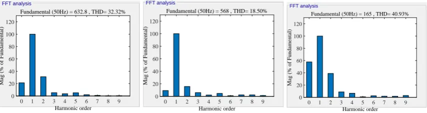
[image:5.595.84.512.87.200.2]Fundamental (50Hz) = 632.8 , THD= 32.32%
Figure 17.Harmonic spectrum for load cur-rentIφ,awith the SAPF.
FFT analysis
0 1 2 3 4 5 6 7 8 9
Harmonic order
0 20 40 60 80 100 120
Mag (% of Fundamental)
Fundamental (50Hz) = 568 , THD= 18.50%
Figure 18.Harmonic spectrum for load cur-rentIφ,bwith the SAPF.
FFT analysis
0 1 2 3 4 5 6 7 8 9
Harmonic order
0 20 40 60 80 100 120
Mag (% of Fundamental)
Fundamental (50Hz) = 165 , THD= 40.93%
Figure 19.Harmonic spectrum for load cur-rentIφ,cwith the SAPF.
15 MVA, 33 kV three-phase source 50 Hz block feeds the load. The load voltages and currents waveforms are shown in Figs. 4, 5, 6, 7, 11, 12&13 and are highly nonlinear. The voltages of arc ignition decrease as a consequence of the short-circuit cur-rent, which is limited by the power system impedance of5Ω. Figs. 14, 15&16 show that the distortion levels are unaccept-able, and the need for a SAPF becomes evident. As a conse-quence, the THD current levels decreased by63.86%,69.73%
and42.69%. The system was upgraded by connecting a SAPF The THD levels for the three-phase currents are enhanced to
19.01%,16.2%and16.4%.
Table 1.THD with and without the SAPF.
THD% Iφ,a Iφ,b Iφ,c
Without SAPF 89.43 61.21 71.42 With SAPF 32.32 18.5 40.93
Table 2.Comparison between with and without SAPF
Without SAPF With SAPF Phase Irms(A) Vrms(V) Φ(deg) Irms(A) Vrms(V) Φ(deg)
Phase a 377.47 1.945×10⁴ 3.8 416.56 1.953×10⁴ 3.02
Phase b 345.44 1.976×10⁴ 4.01 399.97 1.987×10⁴ 3.05
Phase c 358.68 1.975×10⁴ 4.50 405.47 1.976×10⁴ 3.28
5
Conclusions
The presence of harmonics can cause a wide range of fail-ures and malfunctions in a power system grid. Hence, har-monics are not to be ignored. A certain level of harhar-monics is acceptable, especially in power plants with high nonlinearities. However, action should be taken to guarantee that this limited is not exceeded to avoid utility penalties and misoperation.
In this paper, a three-phase SAPF for current harmonic com-pensation is proposed based on the principle of inserting neg-ative harmonics into the network, thus eliminating the unde-sirable harmonics. Practical measurements performed on the UISM factory bus bar for different factory and national power system grid loads are used to validate the proposed active power filter, showing that the intended SAPF has adequate ef-fectiveness in terminating harmonic current.
In future work, more research should focus on issues such as harmonic measurement devices and malfunction of electrical
components due to harmonics, including noise in transformers and rotating electrical machines. In addition to the potential economical impacts, the sizing and rating of components, util-ity penalties, power factor correction and capacitor resonances due to harmonics and harmonic measurement devices are also important factors.
Acknowledgements
The authors would like to thank the United Iron and Steel Manufacturing Company (UISM), Amman, Jordan.
REFERENCES
[1] C. J. Wu, J. C. Chiang, S. S. Yen, C. J. Liao, J. S. Yang, and T. Y. Guo, 1998. ”Investigation and mitigation of harmonic amplification problems caused by single-tuned filters”, IEEE Trans. Power Delivery, pp. 800-806.
[2] Informa, ”Electrical construction &maintenance magazine”, 2018.
[3] Kalair, A., et al. ”Review of harmonic analysis, modeling and mitigation techniques,. Renewable and Sustainable Energy Reviews” 78 (2017): 1152-1187.
[4] Mishra, Anirban, P. M. Tripathi, and Kalyan Chatterjee. “A review of harmonic elimination techniques in grid connected doubly fed induction generator based wind energy systemc,” Renewable and Sustainable Energy Reviews 89 (2018): 1-15.
[5] West, Nathan Thomas, et al. “Variable frequency drive active harmonic mitigation controls and diagnostics,” U.S. Patent No. 9,654,049. 16 May 2017.
[7] Tareen, Wajahat Ullah, et al. “Active power filter (APF) for mitigation of power quality issues in grid integration of wind and photovoltaic energy conversion system,” Renewable and Sustainable Energy Reviews 70 (2017): 635-655
[8] Akagi, Hirofumi, Edson Hirokazu Watanabe, and Mauricio Aredes. “Instantaneous power theory and applications to power conditioning,” Vol. 62. John Wiley&Sons, 2017.
[9] A. E. Emanuel, ”On the assessment of harmonic pollution of power systems,” in IEEE Transactions on Power Delivery, vol. 10, no. 3, pp. 1693-1698, July 1995.doi: 10.1109/61.400958.
[10] P´erez-Loya, J. Jos´e, C. Johan D. Abrahamsson, and Urban Lundin. ”Electromagnetic losses in synchronous machines during active compensation of unbalanced magnetic pull.” IEEE Transactions on Industrial Electronics 66.1 (2019): 124-131.
[11] Wang, Lei, Man-Chung Wong, and Chi-Seng Lam. ”Mitigation of the Harmonic Injection in TCLC Part and Nonlinear
Hystere-sis PWM Control in Active Inverter Part of Thyristor Controlled LC-Coupling Hybrid Active Power Filter (TCLC-HAPF).” Adaptive Hybrid Active Power Filters. Springer, Singapore, 2019. 47-73.
[12] Hogan, Diarmaid John, et al. ”An Adaptive Digital-Control Scheme for Improved Active Power Filtering Under Distorted Grid Conditions.” IEEE Transactions on Industrial Electronics 65.2 (2018): 988-999.
[13] Pradhan, Manik, and Mahesh Kumar Mishra. ”Dual PQ Theory based Energy Optimized Dynamic Voltage Restorer for Power Quality Improvement in Distribution System.” IEEE Transactions on Industrial Electronics (2018).
![Figure 1. Percentages of the harmonic mitigation market by technology [2].](https://thumb-us.123doks.com/thumbv2/123dok_us/8753434.892413/1.595.305.544.312.487/figure-percentages-harmonic-mitigation-market-technology.webp)
![Figure 3. Control scheme for the SAPF [8].](https://thumb-us.123doks.com/thumbv2/123dok_us/8753434.892413/3.595.43.290.214.426/figure-control-scheme-for-the-sapf.webp)