Journal of Chemical and Pharmaceutical Research, 2014, 6(6):1441-1447
Research Article
CODEN(USA) : JCPRC5
ISSN : 0975-7384
The mathematical description of mass diffusion coefficient at
interference fringes maximum point
Li Hua
1, Fei ji-you
1*, Jiang wei-guang
1and Zhang Ying
21
Dalian Jiao Tong University, Dalian, China
2
Xi’an Jiaotong University, Xi’an, China
_____________________________________________________________________________________________
ABSTRACT
Based on the Second Fick Law, a mathematical model of mass diffusion was established by using the principle of diffusion process in semi-infinite plate. The maximum interference fringes parameters were determined with experimental method of Laser holographic interference, and the mathematical description of liquid-liquid mass diffusion coefficient was obtained. The maximum value of interference fringes produced by sucrose solution at a concentration of
0.10mol L
⋅
−1 diffusing to water was measured at 15℃, and the mass diffusion coefficient of sucrose solution was calculated.The error is 3.67% and the standard deviation is 0.378 comparing to the values in other papers. The result demonstrates the accuracy of the diffusing formula using for the interference fringes maximum point, provides a beneficial reference to the research of mass diffusion coefficient theory for new refrigerants, which is urgently required in chemical engineering application.Keywords: The Second Fick Law; mass diffusion coefficient; laser holographic interference
_____________________________________________________________________________________________
INTRODUCTION
It is difficult to provide an accurate mathematical description of the liquid crystal lattices as the liquid molecules lack the regular crystal lattices due to the effect of the interactive forces between molecules. The previous researchers have proposed many experimental models based on the different theories of liquid mass diffusion. However, the research of measuring liquid-liquid mass transfer and diffusion is seldom reported and the work is far more difficult than those of gas and solid, since the liquid molecules are in the state of interactions with each other because of the much more complicated structure of liquid, the higher stacking density of molecules, the shorter average distance between molecules, and the irregular crystal lattices. Therefore, the theoretical research on liquid-liquid mass diffusion phenomenon should be investigated further. In this paper, a mathematical model of liquid-liquid mass diffusion is established based on the interference fringes at the maximum point, which provides the theory foundation for the alternatives of refrigerant and fuel[1,2].
THE DEDUCTION OF THE LIQUID-LIQUID MASS DIFFUSION COEFFICIENT Introduction of mass diffusion equation
The diffusion process is similar to that of the heat conduction of substance if there are different concentrations in the solution, which is the solute diffuses from the region of greater concentration to the one of less concentration.
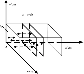
It is assumed that there is a rectangle plate of semiconductor as shown in Fig.1, each section area covering point z are equal and is supposed to
A
/cm2. A certain impurity with the concentration of C 1______________________________________________________________________________
[image:2.595.233.403.118.268.2]moment). Taking an infinitesimal
dz
from the position Z, if its volume is expressed asv
=
∫
Adz
, the impurity amount of this plate can be calculated according to Eq.(1).Fig. 1: The scheme of mass diffusion principle
( )
,
( )
,
m
=
∫
C z t dv
=
∫
C z t Adx
(1)The amount increment of the impurity in this infinitesimal from the time
t
tot
+
dt
is obtained based on the following equation.( )
,
t
m
m dt
AC z t dzdt
∆ =
∫
=
∫
(2) According to the Nernst distribution law, the amount of impurity diffusing from the position z of Section A into the infinitesimal can be calculated based on Eq.(3).( )
1
,
C z t
C
m
D
Adt
D
Adt
n
z
∂
∂
=
= −
∂
∂
∫
∫
(3) Where D (D
>
0
) is the diffusion coefficient and, n is the outside normal direction and the negative symbol expresses the diffusion direction opposite to the direction of concentration gradient. The diffusion direction of the impurity is toward to that of concentration decrease.The amount of the impurity diffusing from the section
z
+
dz
into the infinitesimal within the timedt
is derived from Eq. (4)∫
=
∫
+
∂
+
∂
=
Adt
DC
z
dz
t
Adt
n
t
dz
z
C
D
m
2(
,
)
z(
,
)
(4)Likewise, the amount of the impurity diffusing into the infinitesimal is
∫
+
−
=
∫
=
+
=
m
m
DA
C
z
dz
t
C
z
t
dt
DAC
dzdt
m
2 1[
z(
,
)
z(
,
)]
zz (5)According to the law of conservation of matter, there exists the following relationship:
m
m
∆ =
(6)Eq.(6) can be represented by Eq.(7), and Eq.(7) is the diffusion equation in one dimension.
( )
,
zz( )
,
C z t
=
DC
z t
(7)( )
,
xx( )
,
yy( )
,
zz( )
,
C z t
=
D C z t
+
C z t
+
C z t
(8)The deduction of concentration equation[3-5]
Based on the Second Fick Law and the heat transfer Fourier law, the general conversation equation of the mass diffusion coefficient is deduced by
( )
2( )
( )
2
,
,
1
,
C z t
C z t
A
C z t
D
t
z
A z
z
∂
=
∂
+
∂
∂
∂
∂
∂
∂
(9)Where, A is the section area of the diffusion occurrence and its unit is
cm
2,C z t
( )
,
is the concentration functionof diffusion position and time and its unit is
mol L
⋅
−1,z
is the direction of solution diffusion and its unit iscm
which is a vector, andD
is the mass diffusion coefficient. If the area is constant, Eq. (9) becomes the unsteady state diffusion equation in one dimension and is called the Second Fick Law:( )
2( )
2
,
,
C z t
C z t
D
t
z
∂
∂
=
∂
∂
(10)Suppose that the solution with concentration
C
2 diffuses into that of concentrationC
1, the boundary conditions are defined as:(1) At the time of
t
=
0
, as for the solution with concentrationC
1, there doesn’t occur the diffusion and there existsthe relationship
C
=
C
1 .(2) At the time of
t
>
0
, according to the experiment principle, i.e. it is assumed that the diffusion occurs and awell mix interface with uniform concentration is generated and its concentration is defined as 1 2
2
C
C
C
=
+
(3) At the time of
t
>
0
, as for the solution with concentrationC
1, the solution diffusion reaches to a balance, andthe concentration in the diffusion direction at infinity (i.e.
z
= ∞
) is expressed asC
=
C
1.Eq.(10) can be figured out based on the above-mentioned boundary conditions. In order to simply the expression of Eq.(10), the variable
ξ
[6] is defined as:4
z
Dt
ξ
=
(11)And Eq.(10) can be represented by
2
2
2
0
d C
dC
d
ξ
+
ξ
d
ξ
=
(12)The corresponding boundary conditions are described as
1 2
0,
2
C
C
C
ξ
=
=
+
(13)1
, C
C
ξ
= ∞
=
(14) And the solution of Eq.(12) is expressed as1 2 1 2
2
2
C
C
C
C
______________________________________________________________________________
Where
2
0
2
serf
ξ
ξe
ds
π
−
=
∫
is the error function ofξ
.The concentrations function at a given time t can be expressed as:
( )
,
1 2 1 22
2
2
C C
C C
z
C z t
erf
Dt
+
−
=
+
(16)The deduction of liquid-liquid mass diffusion coefficient
During the experiment process based on the theory of laser holographic interference, the interference fringes can be shown till the conditions of Eq.(17) can be met[7].
( ) (
,
2
1
)
2
n z t
k
λ
l
∆
=
+
(17)Where,
l
(cm) is the thickness of the container's wall,λ
(nm) is the wave length,k
is an integer, and the position of interference fringes depends on the change of refractivity.Since the diffusion occurs in a limited region, as for the infinite dilution, there exists a linear relationship between the concentration of diffusion solution and the refractivity, which can be expressed as:
( )
,
( )
,
0n z t
=
pC z t
+
n
(18)The function
n z t
( )
,
is related to the diffusion direction and the diffusion time,p
is the linear slope of Function( )
,
n z t
and FunctionC z t
( )
,
, andn
0is the liquid refractivity and is constant when the liquid cannot diffuse. Theliquid refractivity varies with the occurrence of liquid diffusion, the data in a continuous time-step, .i.e.
t
1 andt
2(
t
2>
t
1)
can be recorded, and the relationship of the refractivity change and the diffusion direction can be denotedas:
(
,
) ( ) ( )
,
2,
1n z
t
n z t
n z t
∆
∆ =
−
(19) Because the diffusion process is slowly and the refractivity change is infinity, the r order interference fringes of the positionz
1at the timet
1 can be calculated by(
)
( )
1(
)
1
,
,
n z t
2
1
2
n z
t
t
r
d
t
λ
∂
∆
∆ =
∆ =
+
∂
(20)(
)
( )
2(
)
2
,
,
n z t
2
1
2
n z
t
t
q
d
t
λ
∂
∆
∆ =
∆ =
+
∂
(21)Where
r
andq
are the orders of the interference fringes. Combing Eq.(20) and Eq.(21), Eq.(22) can be obtained.(
) ( ) (
2,
) ( )
1,
2
r
1
n z t
2
q
1
n z t
t
t
∂
∂
+
=
+
∂
∂
(22)For the Eq.(16) and (18), the partial derivative with respect to
t
can be written as:( )
(
)
(
)
2
2 1 4
1 3 2
,
4
z Dt
n z t
p C
C z
e
t
Dt
π
−
∂
−
=
(
)
(
)
1 2 2
2 2 1
1
2
1
ln
4
2
1
q
z
z
z
D
t
r
z
−
+
−
=
+
(24)
EXPERIMENT AND DISCUSSION
The measuring beam path[8] based on digital image[9] holographic interferometry measurement of liquid mass diffusion coefficients as shown in Fig. 2. Laser from He-Ne laser reflected by the plane mirrors, laser beams into the spatial filtering formed parallel light which through the light barrier only retaining the part of the uniform brightness to use. Then the laser beams are divided into two beams by the beam splitter prims, one beam which directly through the beam splitter prims is the object light, another beam which reflected the beam splitter prims is the reference light; both the reference light and the object lght which through the diffusion slot projected on the CCD[10]. Interferograms which through the image acquisition card are collected and stored by the computer, then the real-time interference fringes of different materials and different times can be gained. Through the testing principle we know, the extreme point of changed concentration was found by interference fringes digital image processing, then the diffusion coefficient was gained.
In order to prevent turbulence and back mixing when injecting, the bottom of the diffusion slot is designed tapered honeycomb screen[11]. The diffusion slot is placed in the constant temperature system, which let the experiment in a stable temperature environment.
[image:5.595.175.472.477.714.2]1: He-Ne Laser; 2, 5, 8:Plane Mirror; 3: Spatial filtering; 4, 7: Beam splitter prims; 6: Diffusion slot; 9: CCD Sensor; 10: Computer with Image Acquisition Card
Fig. 2: Digital image holographic interferometer measurement Principle of liquid mass diffusion coefficients
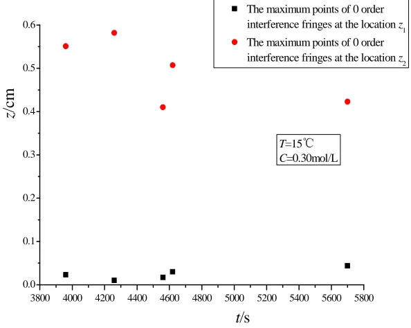
3800 4000 4200 4400 4600 4800 5000 5200 5400 5600 5800
0.0 0.1 0.2 0.3 0.4 0.5 0.6
T=15℃
C=0.30mol/L
The maximum points of 0 order interference fringes at the location z
1
The maximum points of 0 order interference fringes at the location z
2
z/
cm
t/s
______________________________________________________________________________
3800 4000 4200 4400 4600 4800 5000 5200 5400 5600 5800
0.0 0.1 0.2 0.3 0.4 0.5 0.6
T=15℃
C=0.30mol/L
z/
cm
t/s
The maximum points of 0 order interference fringes at the location z1
[image:6.595.167.489.94.321.2]The maximum points of 0 order interference fringes at the location z2
Fig. 4: Maximum point distributions of 1 order interference fringes at the location Z1 and Z2
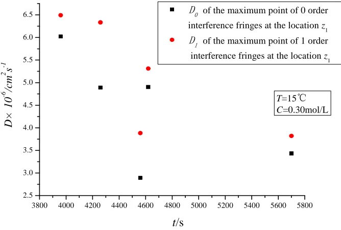
3800 4000 4200 4400 4600 4800 5000 5200 5400 5600 5800
2.5 3.0 3.5 4.0 4.5 5.0 5.5 6.0 6.5
T=15℃
C=0.30mol/L
D
×
1
0
-6
/c
m
2
s
-1
t/s
D
0
of the maximum point of 0 order interference fringes at the location z1
D
1 of the maximum point of 1 order
interference fringes at the location z1
Fig. 5: The mass diffusion coefficient distributions of the maximum points at the location Z1 and Z2
This experiment is carried out based on the theory of laser holographic interference, the conditions are as follows: the sucrose solution with concentration 1
0.30mol L
⋅
− diffuses into the distilled water at the temperature of 15 , and the maximum points are recorded where interference fringes occur.Five groups of the maximum points of 0 orders are plotted in Fig. 3 and five groups of the maximum points of 1 order are plotted in Fig. 4. The maximum points of 0 order and 1 order calculated by Eq.(24) are drawn in Fig.5. The
average coefficient is calculated by 1 0 1 1
( ) ( )
j j
i i
D i D i D
j j
= =
[image:6.595.145.479.374.599.2]6 2 1
4.62 10 cm
×
−⋅
s
− provided by Gosting[12], the error is 3.76%, which verify the validity of the proposedmathematical description D in this paper.
CONCLUSION
Based on the principle of mass diffusion in semi-infinite plate and the Second Fick Law, a mathematical expression of liquid-liquid mass diffusion coefficient at interference fringes maximum point is proposed in this paper. During the experiment process, the data can be obtained by means of the method of laser holographic interference. Taking the sucrose solution with concentration 1
0.10mol L
⋅
− at the temperature of 15℃ as an example, its mass diffusion coefficient at interference fringes maximum point are calculated as 6 2 14.796 10
D
=
×
−cm
⋅
s
− . Comparing with the related researches, the error between them is 3.76%, which verifies the validity of the proposed mathematicaldescription and provides a basic theory foundation for the study of multi-phase liquid-liquid mass diffusion coefficient.
Acknowledgments
The authors wish to thank the National Natural Science Foundation of China for contract 51376028, the National High Technology Research and Development Program 863 of China for contract 2013AA0411108, under which the present work was possible.
REFERENCES
[1] FEI Jiyou, ZHANG Yunhong, ZHANG Ying, HE Maogang. Journal of Dalian Jiaotong University, v.28, n.4, pp.22-25, 2007.
[2] FEI Jiyou, JIANG Weiguang, LI Lin. Control and Instrument in Chemical Industry, v.36, n.1, pp.57-59, 2009. [3] Mattisson C. Chemistry and Physics of Liquids, v.84, pp.1-12, 1996.
[4] Cussler E L. Diffusion Mass Transfer in Fluid Systems, pp.9-18, 2000.
[5] N. Matsunaqa, M. Hori., Heat Transfer Asian Research, v.31, n.3, pp.182-193, 2002
[6] Abramowitz M,Strgum IA. Handbook of mathematical functions with formulas, graphs and mathematic-al tables, New York Dover, pp. 297-299, 1972.
[7] MA Youguang, LIANG Junai, LIE Mingxia. Chemical Industry Engineering, v.19, n.1, pp. 57-58, 2002.
[8] FEI Jiyou, ZHANG Yunhong, ZHANG Ying. Control and Instrument in Chemical Industry, v.34, n.6, pp.54-57,
2007.
[9] FEI Jiyou, TU Juan. Control and Instrument in Chemical Industry, v.35, n.5, pp.46-50, 2008.