International Journal of Emerging Technology and Advanced Engineering
Website: www.ijetae.com (ISSN 2250-2459, Volume 2, Issue 3, March 2012)403
Load Frequency Control Using Classical Controller in An
Isolated Single Area and Two Area Reheat Thermal
Power System
Kallol Das
1, Priyanath Das
2, Sharmistha Sharma
31P.G. Scholar, NIT Agartala, India.
2Associate Prof. Elect. Engg. Dept., NIT Agartala, India.
3
Assistant Prof. Elect. Engg. Dept., NIT Agartala, India
.
1[email protected]3
Abstract—In this paper, Load Frequency Control (LFC) of isolated single area and two-area re-heat inter-connected thermal power system has been carried out by the classical controllers i.e. I, PI and PID; and implemented on the system at 1% step load perturbation under nominal loading conditions. The system responses have been simulated in MATLAB R2010a. Responses of deviation in frequencies, deviation in tie-line power and choosing the optimum controller (i.e. better among I, PI & PID controllers) gain values (i.e. ) to have better dynamic responses of
the system have been plotted, keeping in view the characteristics such as rise time, settling time, oscillations & peak overshoot. Thus, on the basis of these responses, the dynamic performance of the system has been studied. Effect of variation in regulation parameter (R) and also step load perturbations is simulated for different values. The simulation results indicate that better control performance in terms of overshoot and settling time can be achieved by choosing PID among the other considered classical controllers.
Keywords— Automatic Generation Control, Controllers (I, PI & PID), Frequency Deviation, Generation Rate Constraints, Load Frequency Control, Single Area Power System, Two Area Interconnected Power System, Tie-line Power Deviation.
I. INTRODUCTION
System load is never steady. The main objective of power system operation and control is to maintain continuous supply of power with an acceptable quality, to all the consumers in the system. The system will be in equilibrium, when there is a balance between the power demand and the power generated. As the power in AC form has real and reactive components: the real power balance; as well as the reactive power balance is to be achieved.
Thus steam input to turbine must be continuously regulated to match the active power demand. The system frequency otherwise will change which is not desirable. (A change in the electric power consumption will result in a deviation of the frequency from its steady state value [1]. The consumers require a value of frequency and voltage constant. To maintain these parameters, controls are required on the system and must guarantee a good level of voltage with an industrial frequency).
International Journal of Emerging Technology and Advanced Engineering
Website: www.ijetae.com (ISSN 2250-2459, Volume 2, Issue 3, March 2012)404
Turbine Ste am
Generator
Excitation Controlle r
Ste am valv e
Controlle r vref
fref P+jQ
Voltage Se nsor and Comparator
[image:2.612.83.274.137.243.2]Freque ncy Sensor and Comparator
Fig 1: Load frequency and excitation controller of generator [2].
II. SINGLE AREA THERMAL POWER SYSTEM
Single area power system consists of a governor, a turbine and a generator with feedback of regulation constant. System also includes step load change input to the generator. This work mainly related with the controller unit of a single area power system. Non-reheat type single area thermal generating system represented by block diagram of closed loop controlled system model is shown in Fig 2. Here generation rate constraints are also avoided.
Fig2: Single area thermal power generation model [10].
A. Simulation Results and Analysis
In single area non-reheat thermal power station, by using the controllers (I, PI & PID) optimal controller parameters were obtained as shown in Table I.
Controllers
I - -.2673 -
PI 0.0427 -.2293 -
PID -.129 -.3383 -.0258
Table I: Controller gain values for the single area thermal power model.
[image:2.612.321.574.155.558.2]The dynamic responses of the single area thermal power station depend upon these above controller gain values.
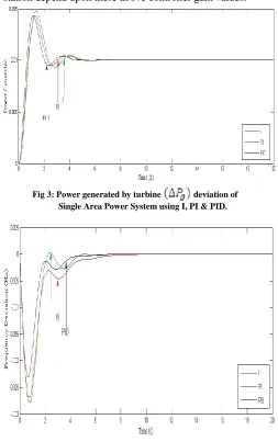
Fig 3: Power generated by turbine deviation of Single Area Power System using I, PI & PID.
Fig 4: Frequency (∆f) deviation of Single Area Power System for step load perturbation of 0.01 using I, PI & PID.
The dynamic responses of single area thermal plant (fig 1) due to the presence of controllers (I, PI & PID) are shown in fig 3& fig 4 for the power generated by turbine & frequency deviation for 1% change in demand load at R= 2.4 Hz . The frequency response for the PID controller
[image:2.612.51.282.389.561.2] [image:2.612.43.295.635.715.2]International Journal of Emerging Technology and Advanced Engineering
Website: www.ijetae.com (ISSN 2250-2459, Volume 2, Issue 3, March 2012)405 B. Tuning of PID for Single Area Thermal Power Plant
As PID has been rendering better performance characteristics, so tuning of PID [4] [6] for more precisely good response is simulated selecting randomly some PID controller gain values.
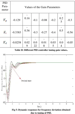
PID
Para-meter Values of the Gain Parameters
-0.129 -0.16
-0.1 -0.08 -0.2 -0.2
5 -0.3
-0.3383 -0.36
-0.3 -0.27 -0.4 -0.5 -0.56 -0.0258 -0.02 9 -0.0 22 -0.01 8 -0.03 5 -0.0 4 -0.05
[image:3.612.44.302.198.589.2]Table II: Different PID controller tuning gain values
.
Fig 5: Dynamic responses for frequency deviation obtained due to tuning of PID.
Keeping all the dynamic characteristics (i.e. rise time, settling time, oscillation & overshoot) in view, the tuning of PID controller with randomly selecting gain values yielding different responses as shown in fig 5, is done to obtain a suitable system response.
III.
T
WO-A
REAI
NTERCONNECTEDT
HERMALP
OWERS
YSTEMA two-area re-heat type thermal system consists of two single areas connected through a power line called the tie-line as shown in fig 6. Each area feeds its user pool and tie-line allows the electric power to flow between areas [5].
[image:3.612.323.582.240.425.2]Since both areas are tied together, a load agitation in one area affects the output frequencies of both areas as well as the power flow on the tie-line. In this figure, reheat and generation rate constraints (GRC) are considered [9]. GRC inclusion increases the system non-linearity much more and if in that condition, the controller used responds more precisely to have more stable response, then linearization is achieved in a non-linear environment.
Fig 6: Two-area unequal re-heat Thermal Power System [11].
A. Simulation Results and Analysis
Now for the above two area reheat thermal power station, by using the controllers (I, PI & PID) optimal controller gain values for the two areas were obtained as shown in Table III.
Controll ers Area 1 Area 2 Area 1 Area 2 Area 1 Area 2
I - -
-.2746
-.4680 - -
International Journal of Emerging Technology and Advanced Engineering
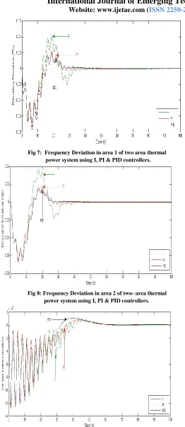
Website: www.ijetae.com (ISSN 2250-2459, Volume 2, Issue 3, March 2012) [image:4.612.48.310.111.714.2]406 Fig 7: Frequency Deviation in area 1 of two area thermal power system using I, PI & PID controllers.
Fig 8: Frequency Deviation in area 2 of two- area thermal power system using I, PI & PID controllers.
Fig 9: Tie-line Power Deviation using I, PI & PID controllers.
B. Dynamic Response Analysis
When an electrical load change occurs, the turbine-generator rotor accelerates or decelerates, and frequency undergoes a transient disturbance. The controller should not allow transient oscillations or overshoot, which in-turn trips the under-frequency relay connected in the system. Oscillations, settling time and overshoot are inter-related; changes in one parameter will affect the other parameter. Hence, it is important that the designed controller must be efficient in selecting the optimum gains in order to achieve better results [12].
The value of R determines the slope of the governor characteristics and it determines the change on the output for a given change in frequency. In practice, R is set on each generating unit so that change in load on a system will be compensated by generated output. The speed governor system should be operated within the restricted control range of feedback gains due to system instability [7]. Therefore, higher value of step load perturbation
for a small R value will produce oscillations into the system. With higher value of R, the oscillations of the system responses increase largely and settling time also increases as shown in Table IV & V. Hence are selected accordingly to obtain optimum results in terms of settling time & oscillations. It is also seen that with high value of tie-line power, system performance deteriorates.
Simulation results for the unequal thermal area system cons considering R=4% and 𝛃=0.425 for each area as shown in fig. 7, 8 & 9 gives better response for the PID controller in terms of peak overshoot, settling time & oscillations than that of I & PI controllers.
Rise time (s) Settling time (s)
Controllers Area 1 Area 2 Area 1 Area 2
I 12.5 s 13.5 s 55 s 80 s
PI 15.5 s 14 s 61 s 55.5 s
[image:4.612.319.600.470.591.2]PID 15 s 14.5 s 44.5 s 46 s
Table IV: Performance analysis for R = 2.4 Hz/ MW at and
Analysis shows that due to increase of step load perturbation, i.e. and ; the settling time for each of the
controllers increase rapidly, resulting in much more oscillation. Therefore, the frequency response at small load change
International Journal of Emerging Technology and Advanced Engineering
Website: www.ijetae.com (ISSN 2250-2459, Volume 2, Issue 3, March 2012)407 Settling time (s)
Controllers Area 1 Area 2
I 65 s 59 s
PI 50 s 53 s
PID 42.5 s 43 s
Table V: Performance analysis for R = 3 Hz/ MW
.
[image:5.612.316.583.110.413.2]Analysis reveals that due to higher value of speed regulation parameter, frequency oscillation increases sharply resulting in larger oscillation & settling time. Among all the responses it is observed that PID is the classical controller rather than I & PI controllers whose performance characteristics is better in terms of settling time & oscillations for both frequency and tie-line power.
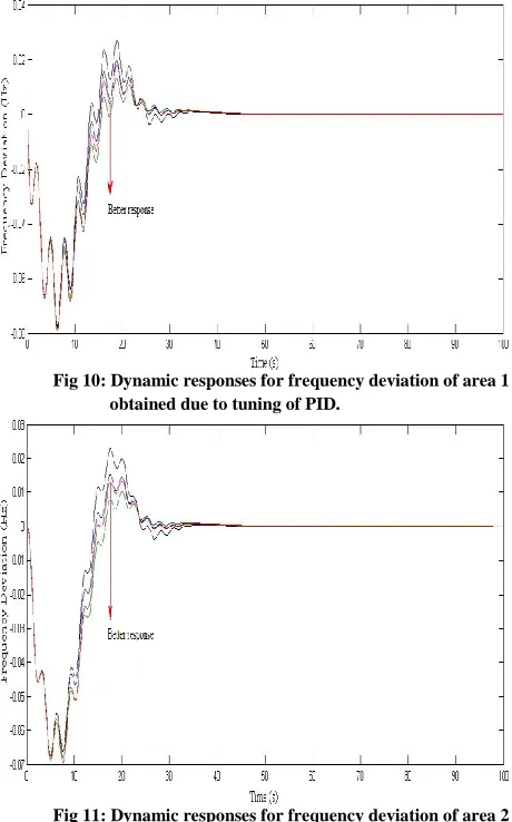
Fig 10: Dynamic responses for frequency deviation of area 1 obtained due to tuning of PID.
[image:5.612.67.297.134.242.2]Fig 11: Dynamic responses for frequency deviation of area 2 obtained due to tuning of PID.
Fig 12: Dynamic responses for tie-line power deviation obtained due to tuning of PID.
AREA 1 AREA 2
-.1509 -.2742 -.1110 -.0021 -.2019 -.003
-.2222 -.3333 -.1580 -.0044 -.2580 -.0058
-.1130 -.2160 -.0870 -.0012 -.1670 -.0014
-.2930 -.2820 -.1970 -.0055 -.2080 -.007
Table VI: Different PID controller tuning gain values.
Tuning of PID gives more precisely suitable dynamic responses improving stability of the system as shown in above simulated figures.
IV.
C
OMPARISONO
FE
QUAL &U
NEQUALT
WO-A
REAR
E-H
EATT
HERMALP
OWERS
YSTEM [image:5.612.59.289.349.718.2]Difference in Dynamic Response characteristics between two-area equal and unequal thermal power system are as follows:
Fig 13: Frequency Deviation response in area 1 at R=4% & for two-area equal & unequal
[image:5.612.323.577.548.688.2]International Journal of Emerging Technology and Advanced Engineering
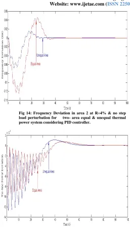
Website: www.ijetae.com (ISSN 2250-2459, Volume 2, Issue 3, March 2012) [image:6.612.47.304.117.566.2]408 Fig 14: Frequency Deviation in area 2 at R=4% & no step load perturbation for two- area equal & unequal thermal power system considering PID controller.
Fig 15: Tie-line power deviation response for two-area equal & unequal thermal power system consider-ing PID controller.
The output response of any system also varies according to the rated power capacity of any system. Therefore, due to different rated power capacity and equal power capacity of area 1 & 2, the dynamic responses for both frequency and tie-line power will also be different. And the variation in responses is shown in fig 13, 14 & 15. It has been observed that the peak overshoot, oscillation and the settling time for the equal area thermal power plant are relatively higher than that of the two-area unequal thermal plant and thereby system stability in case of two-area unequal thermal system is achieved faster than the equal area thermal system.
V. CONCLUSION
Among all the responses obtained, it is observed that PID is the classical controller rather than I & PI controllers whose performance characteristics is better in terms of rise time, settling time, oscillations & overshoot for both frequency and tie-line power. Tuning of the controller is also essential for achieving good response and stability with minimum error or disturbance. It is also observed that unequal area thermal power system yields better frequency and tie-line power response as compared to equal area thermal power system.
References
[1] I.J. Nagrath and M. Gopal, Control Systems Engineering, 5thed. New
Age International Publishers, 5th ed. 2007.
[2] Elgard O.I., “Electric energy systems theory: an introduction” McGraw Hill, 1971.
[3] J. Nanda, B. L. Kaul, “Automatic generation Control of an Interconnected Power System”, IEE Proc., vol. 125, No. 5, May 1978, pp. 385-391.
[4] Wen Tan, “Tuning of PID load frequency controller for power systems.” Energy Conversion and Management 50 (2009) 1465-1472. [5] Armin Ebrahimi Milani, Babak Mozafari, “Genetic Algorithm Based
Optimal Load Frequency Control In Two-Area Interconnected Power Systems,” Global Journal of Technology & Optimization volume 2, 2011.
[6] Youssef L. Abdel-Magid, M. A. Abido, “AGC tuning of interconnected reheat thermal systems with particle swarm optimization”.0-7803-8163-7/03 @2003 IEEE.
[7] A. Soundarajan, S. Sumathi and G. Sivamurugan, “Hybrid Evolutionary Algorithms For Frequency and Voltage Control In Power Generating System”, Ictact Journal On Soft Computing, October 2010, issue 02.
[8] S.K. Sinha, Dr. R Prasad and Dr. R. N. Patel, “Design of Optimal and Integral Controllers For AGC of Two-Area Interconnected Power System,” XXXII National Systems Conference, NSC 2008, December 17-19, 2008.
[9] Young-Hyun Moon, Heon-Su Ryu, Jong-Gi Lee, Kyung-Bin Song, Myong-Chul Shin, “Extended integral control for load frequency control with the consideration of generation rate constraints,” Electrical Power and Energy Systems 24 ((2002) 263-269.
[image:6.612.51.302.128.336.2]International Journal of Emerging Technology and Advanced Engineering
Website: www.ijetae.com (ISSN 2250-2459, Volume 2, Issue 3, March 2012)409
[11] B. Prasad Padhy and Barjeev Tyagi, “Tuning of PID Controller Used In AGC Scheme With Genetic Algorithms”, XXXII NATIONAL SYSTEMS CONFERENCE, NSC 2008, December 17-19, 2008. [12] A. Soundarrajan in IAENG, “Particle Swarm Optimization Based