International Journal of Emerging Technology and Advanced Engineering
Website: www.ijetae.com (ISSN 2250-2459, Volume 2, Issue 2, February 2012)12
Controller Area Network for Vehicle Automation
Ashwini S. Shinde
1, Prof. vidhyadhar B. Dharmadhikari
21Post Graduate Student of Walchand College of Engineering, Sangli, Maharashtra, India.
2 Associate professor, Department of Electronics Engineering, Walchand College of Engineering, Sangli.
1
Abstract—Based on requirements of modern vehicle,
in-vehicle Controller Area Network (CAN) architecture has been implemented. In order to reduce point to point wiring harness in vehicle automation, CAN is suggested as a means for data communication within the vehicle environment. The benefits of CAN bus based network over traditional point to point schemes will offer increased flexibility and expandability for future technology insertions.
This paper describes the ARM7 based design and implementation of CAN Bus prototype for vehicle automation. It focus on hardware and software design of intelligent node. Hardware interface circuit mainly consists of MCP2515 stand alone CAN-Controller with SPI interface, LPC2148 microcontroller based on 32-bit ARM7 TDMI-S CPU and MCP2551 high speed CAN Transceiver. MCP2551 CAN Transceiver implements ISO-11898 standard physical layer requirements. The software design for CAN bus network are mainly the design of CAN bus data communication between nodes, and data processing for analog signals. The design of software communication module includes system initialization and CAN controller initialization unit, message sending unit, message receiving unit and the interrupt service unit.
Keywords—Vehicle Automation, Controller Area Network
(CAN), Electronic Control Unit (ECU), CANopen, LIN, SAE J1939.
I. INTRODUCTION
Intoday’s world, automation is needed in many systems
which provide better performance. Large numbers of systems are fully automated. Vehicle system is composed of automotive electrical architectures consist of a large number of electronic control units (ECU) carrying out a variety of control functions. In vehicle system we generally want greater safety, more comfort, convenience, pollution control and less fuel consumption. A modern vehicle may have many electronic control units (ECU) for various subsystems. Different suchsubsystems are airbags, antilock braking, engine control, audio systems, windows, doors, mirror adjustment etc. Some of these subsystems form independent or dependent subsystems. Communications among dependent sub systems is essential.
Traditional electronic control system can improve a vehicle dynamics, economy and comfort. But some problems also have come up, such as the body wiring complexity, space constraints and some reliability issues. In order to solve these problems, the vehicle network technology has been created. In-vehicle networking protocols must satisfy requirements which include, significant reduction of wiring harness, reducing body weight and costs, improving the efficiency of fault diagnosis, low latency times and configuration flexibility and enhancing the level of intelligent control [4]. Sub-systems (ECU) require the exchange of particular performance and position information within defined communication latency. Therefore the requirement for each ECU is to communicate via some kind of network technology such as CAN (Controller Area Network) bus. At present, some vehicle buses have been already put into use, such as CAN bus, LIN (Local Interconnect Network) bus, Flexray bus etc. In the proposed work CAN bus protocol is used for vehicle automation
1. LIN
LIN is the communication protocol for the low cost, low SPEED vehicle network. In the low speed and low cost applications, LIN bus can be used in association with CAN bus, so that reliability of whole system increases. LIN bus is based on Master/Slave structure, using single-wire communication and decrease the weight and wires greatly [6]. Its target application is low speed system, such as switch type equipment and position type system which are including control of the rearview mirrors, locks, car seat, windows etc.
2. FlexRay
The complexity of modern vehicle electrical
International Journal of Emerging Technology and Advanced Engineering
Website: www.ijetae.com (ISSN 2250-2459, Volume 2, Issue 2, February 2012)13
Benefits of the application of FlexRay in automotive control are: - FlexRay provides features such as larger CRC, dual redundancy, fast data rate which allows faster real-time controlloops [6].
II. OVER VIEW OF CAN PROTOCOL
Controller area network (CAN) provide high reliability and good real-time performance with very low cost. Due to this, CAN is widely used in a wide range of applications,
such as in-vehicle communication, automated
manufacturing and distributed process control
environments.CAN bus is a serial data communication protocol invented by German BOSCH Corporation in 1983. CAN is a network protocol which is designed for the car industry. Since data communication in car often have many sensors transmitting small data packets, CAN supports data frames with sizes only up to 8 bytes. Meanwhile, the 8 bytes will not take the bus for a long time, so it ensures real-time communication. CAN use a large amount of overhead, which combined with a 15-bit CRC makes CAN very secure and reliable.
[image:2.612.325.570.241.423.2]CAN protocol use non-destructive bitwise arbitration process to access shared resource. CAN protocol define a logic bit 0 as a dominant bit and a logic bit 1 as a recessive bit, each transmitting node monitors the bus state and compares the received bit with the transmitted bit. If a dominant bit is received when a recessive bit is transmitted then the node stops transmitting (i.e. it lost arbitration). Arbitration is performed during the transmission of the identifier field. There are two message formats: Base frame format with 11 identifier bits and Extended frame format with 29 identifier bits.
Figure 1. CAN Data Frame
A. CAN Bus Electrical Characteristics
CAN transmission medium formed by the two, One is called high-level transmission line CANH and another is called low-level transmission line CANL, connected to CANH and CANL pins of MCP2551 CAN transceiver.
VCANH and VCANL be the voltage level of CANH and CANL
lines with respect to ground. The difference between them is called difference voltage Vdiff.
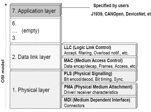
B. Hierarchical structure of CAN BUS
Architecture of CAN protocol based on OSI reference model is as shown in figure 2.2. CAN protocol contain only three layers, physical layer, data link layer and application layer. Application layer has different protocols such as SAE J1939, CANopen, DeviceNet, etc.
Figure II. Hierarchical structure of CAN BUS
C. Scheduling ofCAN BUS
CAN protocol implements fixed priority scheduling of CAN messages. Higher priority node has lower node ID. If available bandwidth is scarce, problems come with traditional fixed-priority based scheduling. It is possible that low priority control loops cannot access the network all the time, since limited resources have been consumed by high priority loops. As a result of tremendous delays, low priority control loops may be destabilized.
The problem of fixed priority is overcome using direct feedback scheduling algorithm, namely MUF (maximum urgency first) is integrated in the network scheduler. Upon invocation, the scheduler calculates the urgency of each control loop based on the set points and current system outputs. According to the MUF algorithm, the scheduler produces new priorities based on these urgency values. And then, messages in different loops will be transmitted in accordance with the newly assigned priorities [9].
International Journal of Emerging Technology and Advanced Engineering
Website: www.ijetae.com (ISSN 2250-2459, Volume 2, Issue 2, February 2012)14
The core idea of MTS is set the relative deadline information into the identifier [8]. Use the earliest deadline first (EDF) message scheduling algorithm for high priority information and the RMS (rate monotonic scheduling) message scheduling algorithm for low priority information.
D. Reliability
Reliability is defined as the probability of no failures in an operational interval. High error handling capability of CAN improves system reliability. If any message transmitting node has detected an error, the node forcibly aborts transmission. Then it attempts to retransmit repeatedly until its message is transmitted successfully. This functionality may let the CAN bus be hogged, if the node of high priority is failed. It is the designer's responsibility to ensure that no any message node hogs the bus. To avoid such crisis, the faculty of the transmit error counter (TEC) and the receive error counter (REC) are started to diagnose the conditions of CAN controller [7]. MCP2515 CAN controller has TEC and REC which enhances reliability of CAN bus system.
A CAN controller can be in one of three states: error active, error passive or bus off state. The operating state of the controller is controlled by two error counters – TEC and REC. The CAN controller is in error active state if TEC less than 127 and REC less than 127. Passive state is used if (TEC greater than 127 or REC greater than 127) and TEC less than 255. Bus off state is entered if TEC is greater than 255. Once the CAN controller has entered bus off state, it must be reset by the host microcontroller in order to be able to continue operation.
III. HARDWARE DESIGN
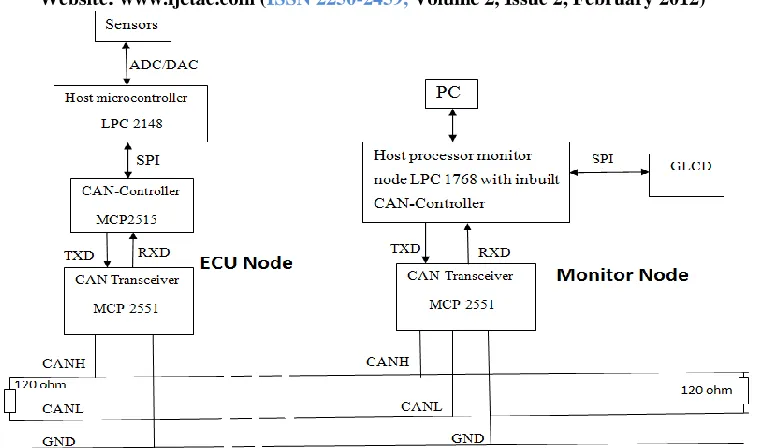
The proposed block diagram for CAN bus
communication system is as shown in figure III. Different nodes are nothing but ECUs, which are connected to each other using CAN bus. Monitor node monitors information on bus and information is send to computer for display and further analysis. CAN analyzer software is used for analysis as well as fault diagnosis of the system.The devices that are connected by a CAN network are typically sensors, actuators, and other control devices. These devices are not connected directly to the bus, but through a host processor and a CAN controller. CAN node consist of host
processor, CANcontroller and CAN transceiver. Individual
node is connected to CAN bus line. CAN bus is terminated at both ends by using 120 ohm resistor.
In proposed CAN bus prototype for vehicle automation, LPC2148 ARM7 TDMI-S processor is used as host processor. MCP2515 is Stand-Alone CAN Controller with SPI Interface provided by Microchip Technology. MCP2551 is used as CAN transceiver. LPC1768 ARM Cortex M-3 processor is having inbuilt CAN controller used for designing monitor node.
A. Host processor
The host processor decides what the meaning of received messages is and which messages it wants to transmit itself. Sensors, actuators and control devices can be connected to the host processor.
B. CAN controller
The CAN controller stores received bits serially from the bus until an entire message is available, which can then be fetched by the host processor. The host processor stores it’s transmit messages to a CAN controller, which transmits the bits serially onto the bus.
C. Transceiver
It adapts signal level from the bus to level that the CAN controller expects and has protective circuitry that protects the CAN controller. It converts the transmit-bit signal received from the CAN controller into a signal that is sent onto the bus.
MCP2515 implements the CAN specification, version 2.0B. It is capable of transmitting and receiving both standard and extended data and remote frames with 0 – 8 byte length of the data field. The MCP2515 has two acceptance masks and six acceptance filters that are used to filter out unwanted messages, thereby reducing the host MCUs overhead. The MCP2515 is interfaced with microcontroller (MCU) via an industry standard Serial Peripheral Interface (SPI). MCP2515 has two receive buffers with prioritized message storage and three transmit buffers with prioritization and abort features.
International Journal of Emerging Technology and Advanced Engineering
Website: www.ijetae.com (ISSN 2250-2459, Volume 2, Issue 2, February 2012) [image:4.612.127.506.126.350.2]15
Figure III. Block diagram
Typically, each node in a CAN system must have a device to convert the digital signals generated by a CAN controller to signals suitable for transmission over the bus cabling (differential output). It allows a maximum of 112 nodes to be connected and a nominal termination resistor value of 120Ω.
A dominant state occurs when the differential voltage between CANH and CANL is greater than a defined voltage (e.g., 1.2V). A recessive state occurs when the differential voltage is less than a defined voltage (typically 0V). The RXD output pin reflects the differential bus voltage between CANH and CANL.
IV. DESIGN SCHEME OF COMMUNICATION PROTOCOL
The design scheme of communication protocol is explained in this section. Identifier of the message is the unique character for the application program to distinguish messages. In this communication system, when a node receives a message correctly (until the last bit of the EOF area is right), the configured filter box filter the message, and then save the messages with matched ID in receiving box. By using this feature, communication protocol can be made. Different identifiers are set for every data type or control command in this system, then distinguish the received messages conveniently, and choose corresponding processing mode.
The standard format of identifier is used in this system. It has 11 bits. Use of standard identifier can reduce the data length and improve data transmission efficiency. In this system, the 11 bit identifier is designed for the “address code + type code” format. Bits D7 to D4 of identifier is the address field, providing at most 16 address codes, and every address code corresponds to a individual node. Bits D3 to D0 is the type field, which can also provide 16 type codes. And the bits D10 to D8 is the backup filed which is used for system expansion. By configuring the value of the filter ID, each node would only receive the messages with the matched address code [2].
Figure IV. Identifier format
V. CAN BUS NETWORK SOFTWARE DESIGN
International Journal of Emerging Technology and Advanced Engineering
Website: www.ijetae.com (ISSN 2250-2459, Volume 2, Issue 2, February 2012)16
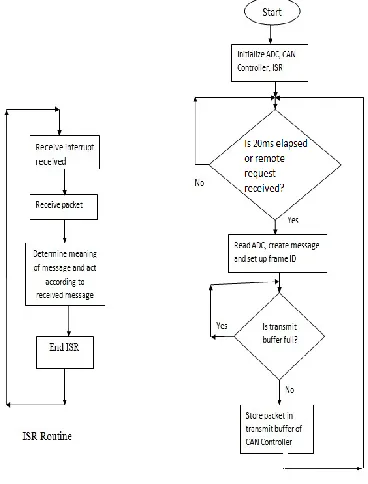
System initialization unit, CAN initialization unit, message sending unit, message receiving unit and interrupt service unit.
[image:5.612.80.264.245.487.2]System initialization unit includes initialization of host processor i.e. LPC2148 and monitor node LPC1768. Flow chart for CAN node is shown in figure V.
Figure V. CAN bus node design process
A. CAN Controller Initialization
CAN controller initialization process include initialization of internal register of CAN controller MCP2515, such as initialization of transmit and receive buffer. When initializing the CAN registers in the MCP2515, the system immediately clear the read and write buffer, Configures the operating mode, bit timing register, filter and mask register, and interrupt enable register.
B. CAN Message Sending
After initialization, the MCP2515 is in normal communication status and is ready to work. The CAN message sending adopts inquiry mode or it sends message when remote request is received.
In inquiry mode, after specific time interval, LPC2148 creates packet and sends data to CAN Controller transmit buffer for further transmission.
C. CAN Message Receiving
There are two ways for messages receiving: inquiry mode and interrupt mode. In system design, interrupt mode is implemented. In interrupt mode, if MCP2515 CAN controller receives valid message in receive buffer, it generates interrupt signal on INT pin. Message is read by LPC2148 by using SPI commands of MCP2515.
VI. CONCLUSION
Real-time, reliability and flexibility, all these characteristics make CAN BUS an indispensable
network communication technology applied in
automobile network communication field. In this paper, the CAN-bus based communication system for vehicle automation is designed. Software system and hardware system are easily to be expanded and upgraded.
References
[1] Li Ran, Wu Junfeng, Wang Haiying, Li Gechen. “Design Method of CAN BUS Network Communication Structure for Electric Vehicle”, IFOST 2010 Proceedings IEEE.
[2] Yujia Wang, Hao Su, Mingjun Zhang., “CAN-Bus-Based Communication System Research for Modular underwater Vehicle”, 2011 IEEE DOI 10.1109/ICICTA.2011.
[3] Chin E. Lin, S. F. Tai, H. T. Lin, T. P. Chen, P. K. Chang, C. C. Kao“Prototype Of A Small Aircraft Avionics Using Hybrid Data Bus Technology” 2005 IEEE
[4] Chin E. Lin, Hung-Ming Yen, “A Prototype Dual Can-Bus Avionics System For Small Aircraft Transportation System” 2006 IEEE.
[5] V. Claesson, C. Ekelin, N. Suri, “The event-triggered and time-triggered medium-access methods”, 6th IEEE International Symposium on Object-Oriented Real-Time Distributed computing, May 14-16, 2003, pp. 131-134.
[6] Chris Quigley, Richard McLaughlin, “Electronic System Inte-Gration For Hybrid And Electric Vehicles”.
International Journal of Emerging Technology and Advanced Engineering
Website: www.ijetae.com (ISSN 2250-2459, Volume 2, Issue 2, February 2012)17
[8] Shurui Fan, Jing Du, Hexu Sun,Tao Liang “Research on Mixed Traffic Scheduling of Networked Control Systems Based on CAN Bus” 2009 IEEE DOI 10.1109/ICINIS.2009.64