International Journal of Emerging Technology and Advanced Engineering
Website: www.ijetae.com (ISSN 2250-2459,ISO 9001:2008 Certified Journal, Volume 3, Issue 1, January 2013)
516
An Intelligent Model Based Level Control of Boiler Drum
K. Ghousiya Begum
1, D.Mercy
2, H. Kiren Vedi
3, M. Ramathilagam
41,4Assistant professor M.A.M College of Engineering, Siruganur, Trichy 2,3
Associate Professor M.A.M College of Engineering, Siruganur, Trichy
Abstract—An Intelligent model is developed to control the water level in Boiler Drum.There are three different types of boiler such as Single element boiler drum level control, two element boiler drum level control and three element boiler drum level control. The parameters of boiler drum level control system are determined using PID control tuning methods such as Ziegler-Nichols method, Tyreus-Luyben method and Internal Model Control (IMC), in which IMC surpasses the performance of the conventional controller.
Keywords—Boiler Drum Level control, PID tuning, IMC, Feed forward, MATLAB.
I. INTRODUCTION
Drum Level Control Systems are used extensively throughout the process industries and the Utilities to control the level of boiling water contained in boiler drums on process plant and help provide a constant supply of steam The purpose of the drum level controller is to bring the drum up to level at boiler start-up and maintain the level at constant steam load. A dramatic decrease in this level may uncover boiler tubes, allowing them to become overheated and damaged. An increase in this level may interfere with the process of separating moisture from steam within the drum, thus reducing boiler efficiency and carrying moisture into the process or turbine. Boiler drum water level control is critical to secure operation of the boiler and the steam turbine. The functions of this control module can be broken down into the following
Operator adjustment of the set point for drum level.
Compensation for the shrink & swell effects.
Automatic control of drum level.
Manual control of the feed water valve.
Bumpless transfer between auto and manual
modes.
Indication of drum level and steam flow.
Indication of feed water valve position and feed water flow.
Absolute/deviation alarms for drum level.
The most basic and pervasive control algorithm used in the feedback control is the Proportional Integral and Derivative (PID) control algorithm.
PID control is a widely used control strategy to control most of the industrial automation processes. The 3 element PID control system is introduced to regulate the drum level with the fixed PID parameters. The control is not ideal because the gains and time constants of the system response change significantly with the change in steam load and disturbances. Therefore, some other controller is required to improve the performance of drum level control system [1].
Internal model control is model based controller structure that provides a suitable framework for satisfying our objectives. The IMC structure which makes use of a process model to infer the effect of immeasurable disturbance on the process output and then counteracts that effect. The controller consists of an inverse of the process mode. Using the IMC design procedure, controller complexity depends exclusively on two factors: the
complexity of the model and the performance
requirements. Furthermore, the proposed procedure provides valuable insight regarding controller tuning effects on both performance and robustness.
In process control industry, model-based control strategy is used to track set point and reject load disturbances. The proposed work illustrates how to design an IMC controller for the boiler level control system using MATLAB.
The followings of the paper includes, Section II describing the types and design of boiler. In Section III development of virtual laboratory is explained. In Section IV result and comparison between the boiler performances is discussed. The paper concludes in Section V.
II. BOILER DRUM LEVEL CONTROL
International Journal of Emerging Technology and Advanced Engineering
Website: www.ijetae.com (ISSN 2250-2459,ISO 9001:2008 Certified Journal, Volume 3, Issue 1, January 2013)
517
It can even result in tube failure due to overheating from lack of cooling water on the boiling surfaces. Normally drum level is expected to be held within 2 to 5cm of the set-point with some tolerance for temporary load changes.
There are several components affecting its operation. Under boiling conditions, steam supporting field products such as bubbles exist below the water/steam level interface. These bubbles have volume and therefore displace water to create a misrepresentation of the true water level in the drum. Another effect upon drum level is pressure in the drum. Because steam bubbles compress under pressure (if the drum pressure changes due to load demands), the steam bubbles expand or contract respective to these pressure changes. A higher steam demand will cause the drum pressure to drop, and the steam bubbles to expand to give the appearance of a water level higher than it truly is. This fictitious higher water level causes the feedwater input to be shut down at a time when more water is really required. A surge in water level as a result of the drum pressure decreasing is called 'swell'. A water level decrease due to drum pressure increase is called 'shrink'. Providing tight water level control in a drum is accomplished by utilizing one of three types of drum level control: single-element, two-element, or three-element [1].
A. Single element drum level control
Single-level element control uses only the level measurement and the feed water valve. The controller responds to a proportional signal from the drum level transmitters by generating a proportional output to the boiler feed water valve when needed. This approach is often used when starting up a boiler and there is no steam flow or when a flow meter has failed. The drawback of this strategy is that the level is subject to uncontrolled disturbances from the steam header and the feed water. For example, if the feed water header pressure rises, the feed water flow to the boiler also increases. Without a feed water control loop, this situation would be uncorrected until the level changes. In addition, the installed characteristics of the feed water valve may compromise level control performance over a large operating range.
B. Double element drum level control
The two-element level control adds the steam flow as a feed forward element to the level controller output. A steam mass flow rate signal is used to control the feed water flow so that feed water demand can be adjusted immediately in response to load changes. The level controller is used to correct any imbalance between the steam mass flow out of and the feed water mass flow into the drum. This approach delivers more effective drum level control than a single element.
It is well suited for use on a single boiler with a single feed water pump using a constant feed water pressure. A potential weakness is that the installed characteristics of the feed water valve may compromise level control performance over a large operating range. In addition, steam feed forward may need to be characterized when using this approach. .
C. Three element drum level control
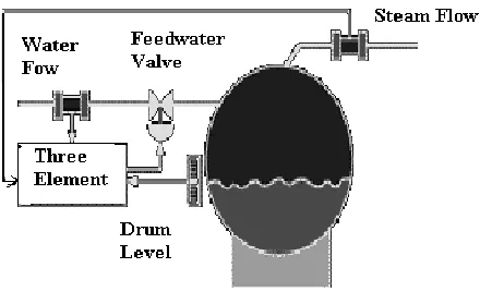
[image:2.612.332.552.393.527.2]Three-element level control as shown in Fig.1 is the most common boiler drum level control strategy. A feed water flow loop slave is added to the two-element strategy. Three-element level control linearizes the feed water flow with respect to the steam flow and the level controller output. The control loop now requests volumetric flow change, not just a change in the valve position. This strategy attempts to compensate for changes or disturbances in steam flow and feed water flow based on the principle that flow in equals flow out. The installed characteristics of the feed water valve are no longer an issue because the flow controller can compensate. Using this approach, the steam feed forward element can be a simple gain without requiring characterization [1].
Fig. 1 Three element boiler drum level control.
III. CONTROL STRATEGIES AND SIMULATION
Control strategies are necessary for any system to perform accurately. Some of these are given below.
D. PID Controller
International Journal of Emerging Technology and Advanced Engineering
Website: www.ijetae.com (ISSN 2250-2459,ISO 9001:2008 Certified Journal, Volume 3, Issue 1, January 2013)
518
The PID controller separately calculate the three parameters i.e. the proportional, the integral, the derivative values. The proportional value determines the reaction to the current error. The integral value determines the reaction based on the sum of recent errors as past error. The derivative value determines the reaction based on the rate at which the error has been changing as a future error. By tuning these three constants in the PID controller algorithm, the controller can provide control action designed for specific process control requirements.
Some applications may require only one or two parameters of the PID controller to provide the appropriate control on system. A PID controller will be called a PI, PD, P or I controller in the absence of the respective control actions. This is achieved by setting the gain of undesired control outputs to zero. PI controllers are very common, since derivative action is very sensitive to measurement noise and the absence of an integral value may prevent the system from reaching its target value due to control action [2].
The simulation results are shown here for different control strategies. The relationship between the feed water flow rate and drum level for the boiler process are expressed by the following equations [3]. The process function, valve function and disturbance function is shown below.
Gp(s)= [0.25(-s+1)] / [s(2s+1)] (1)
Gv(s) = 1/[0.15s+1] (2)
Gd(s)=[ -0.25(-s+1)]/ [s(s+1)(2s+1)] (3)
Following are the process used to determine the PID gain parameter:
1) Ziegler–Nichols Method
[image:3.612.319.568.113.318.2]This method is introduced by John G. Ziegler and Nathaniel B. Nichols [8]. In this method, the Ki and Kd gains are first set to zero. The Kp gain is increased until it reaches the ultimate gain Ku, at which the output of the loop starts to oscillate [4]. Ku is found to be 3.51, Pu is 9.8. Kuand the oscillation period Puare used to set the gains as shown in Table 1.
TABLE.1 Z-N PARAMETERS
Ziegler-Nichol Control Type
Kp Ki Kd
P 0.50 Ku -
PI 0.45 Ku 1.2 Kp/ Pu
PID 0.60 Ku 2 Kp/ Pu Kp Pu/8
Ziegler-Nichol Control Type
Kp Ki Kd
PID 2.1 0.43 2.57
[image:3.612.322.566.386.628.2]These gains apply to the ideal, parallel form of the PID controller. When applied to the standard PID form, the integral and derivative time parameters Tiand Tdare only dependent on the oscillation period Pu. The step response is shown in Fig.2 and Fig.3.
Fig. 2 Step input response
International Journal of Emerging Technology and Advanced Engineering
Website: www.ijetae.com (ISSN 2250-2459,ISO 9001:2008 Certified Journal, Volume 3, Issue 1, January 2013)
519
2) Tyreus-Luyben Method
This method is introduced by Tyreus-Luyen. In this method, the Ki and Kd gains are first set to zero. The P
[image:4.612.322.570.106.278.2]gain is increased until it reaches the ultimate gain Ku, at which the output of the loop starts to oscillate [4]. Kuand the oscillation period Pu are used to set the gains as shown in Table 2. The Z-L and T-L Matlab Simulink Model and the response of the two conventional PID controllers is shown in Fig.4 and Fig.5.
TABLE.2. T-L PARAMETERS
Tyreus –Luyben Control Type
Kp Ki Kd
PI 0.3125 Ku Kp/ 2.2Pu -
PID 0.4545 Ku Kp/ 2.2Pu KpPu/ 6.3
Tyreus –Luyben Control Type
Kp Ki Kd
PID 1.59 0.073 2.47
Fig. 4 Z-L and T-L Matlab Simulink Model
Fig. 5 Response of 2 Conventional PID
3) Internal Model Control (IMC)
The IMC based PID structure uses the process model as in IMC design. In the IMC procedure, the controller Qc(s) is directly based on the invertible part of the process transfer function. The IMC results in only one tuning parameter which is filter tuning factor but the IMC based PID tuning parameters are the functions of this tuning factor. The selection of the filter parameter is directly related to the robustness [5]. The process model is considered
Gp(s)= [0.25(-s+1)]/ [s(2s+1)(0.15s+1)] (4)
and correspondingly the controller output is calculated as
Gc(s) = [1.2s2+8.6s+4]/ [s2+3s+4] (5)
[image:4.612.47.291.242.624.2]The IMC MATLAB Simulink Model and its output response is shown in Fig.6 and Fig.7. Load disturbance given and IMC with feed forward Simulink Model and its output response is shown in Fig.8 and Fig.9.
[image:4.612.322.577.516.640.2]International Journal of Emerging Technology and Advanced Engineering
Website: www.ijetae.com (ISSN 2250-2459,ISO 9001:2008 Certified Journal, Volume 3, Issue 1, January 2013)
[image:5.612.322.577.110.697.2]520
[image:5.612.50.289.114.453.2]Fig. 7 Output response using IMC
Fig. 8 Load disturbance and IMC with feed forward Simulink Model
Fig. 9 Output response with the load disturbance and of IMC with Feedforward
Fig. 10 Simulink model of all the controllers
[image:5.612.49.289.474.636.2]International Journal of Emerging Technology and Advanced Engineering
Website: www.ijetae.com (ISSN 2250-2459,ISO 9001:2008 Certified Journal, Volume 3, Issue 1, January 2013)
521
IV. RESULTS
TABLE.3
COMPARING OF VARIOUS TIME DOMAIN SPECIFICATIONS
Controller Time Domain Specifications
Tr Ts %Mp
ZLPID 4 30 75%
TLPID 4.5 40 20%
IMC 4.2 10 0%
IMCFF 4.1 9 0%
V. CONCLUSION
This paper presents a novel design method by introducing an intelligent model to achieve the expected output. The comparison between the methods are shown. Through the simulation all the controllers perform an efficient search to obtain an optimal solution that achieve better performance criterion with respect to rise time, settling time, percentage of overshoot. The use of IMC with Feed forward controller improves the performance to great extent than both of these Zeigler-Nichol and Tyreus-Luyben PID tuning techniques.
REFERENCES
[1 ] Roopal Agrawal, Umesh C. Pati, ―Design and Data Logging of Three Element Boiler Level Control Using LabVIEW‖, National Conference on Recent Advances in Chemical and Environmental Engineering (RACEE), Rourkela, Jan 2012
[2 ] Xiang fei, ZOU Li hua, ‖Optimization design of PID controller and its application”, 2011 Third International Conference on Measuring Technology and Mechatronics Automation, vol.2, pp. 803-806, Jan 2011.
[3 ] B. Wayne Bequette, Process Control Modeling Design & Simulation, Pearson Education Inc 2003
[4 ] Liu Jinkun, ―MATLAB Simulation of Advanced PID Control[M],‖ Electronic Industry Press, Beijing, 2006, pp. 102-129.
[5 ] I.L.Chien,. and P.S Fruehauf,, ― Consider IMC tuning to improve controller performance‖, Chemical Engineering Progress, pp. 33 - 41. 1990 .
[6 ] A.M.D. Poar, M. O’Malley, Controllers of Ziegler-Nichols type for unstable processes, Int. J. Control 49 (1989) 1273–1284.