International Journal of Emerging Technology and Advanced Engineering
Website: www.ijetae.com (ISSN 2250-2459,ISO 9001:2008 Certified Journal, Volume 3, Issue 5, May 2013)
Robust Video Watermarking Algorithm Using Discrete
Wavelet Transform
D. Hari Hara Santosh
1, Naveen Kumar Sarva
2, Lakshmi Sunitha G.
3, V.S.V. Harish
31Assistant Professor, Dept. of ECE, MVGR College of Engineering, Vzm., Andhra Pradesh 2
Associate Professor, Dept. Of ECE, MLR College of Engineering, Hyd., Andhra Pradesh
Abstract— Everyday very huge amount of data is embedded on digital media or distributed over the internet. The data so distributed can easily be replicated without error, putting the rights of their owners at risk. Even when encrypted for distribution, data can easily be decrypted and copied. One way to discourage illegal duplication is to insert information known as watermark, into potentially vulnerable data in such a way that it is impossible to separate the watermark from the data. These challenges motivated researchers to carry out intense research in the field of watermarking.
A watermark is a form, image or text that is impressed onto paper, which provides evidence of its authenticity. Digital watermarking is an extension of the same concept. There are two types of watermarks: visible watermark and invisible watermark. This project concentrates on implementing watermark in video. The main consideration for any watermarking scheme is its robustness to various attacks. Watermarking dependency on the original image increases its robustness but at the same time watermark should be made imperceptible. In this project, a robust video watermarking scheme using discrete wavelet transform (DWT) domain is proposed. The quality of the watermarked video is enhanced by using wavelet transform. Experimental results demonstrate that it is robust by calculating the peak signal to noise ratio (PSNR) between the watermark image and extracted image.
Keywords— Video watermarking, Robustness, Discrete wavelet transform, Peak signal to noise ratio.
I. INTRODUCTION
With the rapid growth of the Internet and multimedia systems in distributed environments, digital data owners can easily transfer multimedia documents across the Internet. Therefore, copyright protection has become a very vital issue for the digital media. In the recent years, digital watermarking has drawn much attention of researchers as a potential solution of these issues. The basic idea behind watermarking is to insert information (the watermark) into a digital media, which can be later extracted or detected for variety of purposes including identification and authentication purposes. The embedding is done in such a way that it must not cause serious degradation to the original digital media. The digital media is either an image or an audio or a video. If any conflict happens to the copyright identification and authentication, the embedded watermark can be extracted to verify the authority.
In the recent years, a lot of work has been done for securing images but a few works has been done for the videos. Hence, the present work is concentrated on the robust digital video watermarking. Since, the video can be regarded as the sequence of the correlated images.
Therefore, one can do video watermarking either frame-by frame or block-wise (block of consecutive frames). In this paper, a robust video watermarking algorithm is proposed which employs frame-by frame.
First, each frame is transformed into various sub-bands via discrete wavelet transform (DWT) and then one robust sub-band is selected, here the robust sub-band is diagonal part. Watermark embedding[10], is done into the diagonal sub-band. A reliable watermark extraction is developed for extracting watermark from distorted images. Experimental results and comparison with PSNR values shows the robustness and the better performance of the proposed algorithm. Before introducing proposed video watermarking scheme, the requirements of an effective watermarking scheme and the related work are depicted first.
II. REQUIREMENTS OF WATERMARKING SCHEME
Generally, a practical watermarking system embeds some copyright information into the host data as a proof of rightful ownership and must meet requirements. Obviously, different applications have different requirements for watermarking system. Therefore, it is quite difficult to have a unique set of requirements that all watermarking system must satisfy. The requirements with respect to copyright protection and rightful ownership are as follows
(i) Robustness: Robustness refers to the ability of the watermark to be preserved even after distortions introduced by standard or malicious data processing, which may be either intentionally or un-intentionally. These distortions are also known as watermarking attacks.
International Journal of Emerging Technology and Advanced Engineering
Website: www.ijetae.com (ISSN 2250-2459,ISO 9001:2008 Certified Journal, Volume 3, Issue 5, May 2013)
361 (iii) Capacity: Capacity refers to the maximum
amount of information that can be hidden in the media. This directly affects the robustness and perceptual transparency.
(iv) Security: Security refers to the fact that un-authorized persons should neither detect nor read the watermark; however, it must be retrieved correctly by the authorized user.
III. DISCRETE WAVELET TRANSFORM
The Discrete Wavelet Transform (DWT)[1], which is based on sub-band coding, is found to yield a fast computation of Wavelet Transform. It is easy to implement and reduces the computation time and resources required.
The foundations of DWT go back to 1976 when techniques to decompose discrete time signals were devised. Similar work was done in speech signal coding which was named as sub-band coding. In 1983, a technique similar to sub-band coding was developed which was named pyramidal coding. Later many improvements were made to these coding schemes which resulted in efficient multi-resolution [2], analysis schemes.
Filters are one of the most widely used signal processing functions. Wavelets [3], can be realized by iteration of filters with rescaling. The resolution of the signal, which is a measure of the amount of detail information in the signal, is determined by the filtering operations, and the scale is determined by up sampling and down sampling (sub sampling) operation.
The DWT is computed by successive low pass and high pass filtering of the discrete time-domain signal as shown in figure. This is called the Mallet algorithm or Mallet-tree decomposition. Its significance is in the manner it connects the continuous-time Multiresolution to discrete-time filters [4]. In the figure (1), the signal is denoted by the sequence x[n], where n is an integer. The low pass filter is denoted by G
0 while the high pass filter
is denoted by H
0
. At each level, the high pass filter
produces detail information; d[n], while the low pass filter associated with scaling function produces coarse approximations, a[n].
Fig1: Three-level wavelet decomposition tree.
At each decomposition level, the half band filters produce signals spanning only half the frequency band. This doubles the frequency resolution as the uncertainty in frequency is reduced by half. In accordance with Nyquist’s rule if the original signal has a highest frequency of ω, which requires a sampling frequency of 2ω radians, then it now has a highest frequency of ω/2 radians. It can now be sampled at a frequency of ω radians thus discarding half the samples with no loss of information. This decimation by 2 halves the time resolution as the entire signal is now represented by only half the number of samples. Thus, while the half band low pass filtering removes half of the frequencies and thus halves the resolution, the decimation by 2 doubles the scale.
With this approach, the time resolution[5], becomes arbitrarily good at high frequencies, while the frequency resolution becomes arbitrarily good at low frequencies. The filtering and decimation process is continued until the desired level is reached. The maximum number of levels depends on the length of the signal. The DWT of the original signal is then obtained by concatenating all the coefficients, a[n] and d[n], starting from the last level of decomposition.
Fig2: Three-level wavelet reconstruction tree.
Figure2 shows the reconstruction of the original signal from the wavelet coefficients. Basically, the reconstruction is the reverse process of decomposition. The approximation and detail coefficients at every level are up sampled by two, passed through the low pass and high pass synthesis filters and then added. This process is continued through the same number of levels as in the decomposition process to obtain and the original signal. The Mallet algorithm works equally well if the analysis filters, G0and H0, are exchanged with the synthesis filters,
G1 and H1.
International Journal of Emerging Technology and Advanced Engineering
Website: www.ijetae.com (ISSN 2250-2459,ISO 9001:2008 Certified Journal, Volume 3, Issue 5, May 2013)
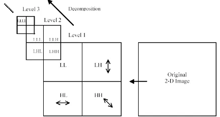
Fig3: Single level analysis filter bank for 2-D DWT
Each decomposition breaks the parent image into four child images. Each of such sub-images is of one fourth of the size of a parent image. The sub-images are placed according to the position of each sub band in the two-dimensional partition of frequency plane as shown in figure 4. The structure of synthesis filter bank follows the reverse implementation of analysis filter bank but with
[image:3.595.56.275.459.576.2]the synthesis filters
h
~
0andh
~
1.Figure 4: Multilevel decomposition hierarchy of an image with 2-D DWT
IV. PROPOSED VIDEO WATERMARKING ALGORITHM
In this section, we discuss some motivating factors in the design of our approach to video watermarking scheme [7]. DWT is used for developing the algorithm. Let us consider host video and color watermark image. The host video is a colour video of size
M
N
3
n
,
We save the positions of robust sub-bands for extraction process. The watermark Wis a binary watermark of size.
N
M
w w the block diagram of proposed algorithm isshown in figure 5.
Fig5: Block diagram of proposed video marked algorithm
A. Embedding process
Embedding Process is given as follows:
In this proposed algorithm, the original video is of the size 640x480. This host video is divided into frames. Then the total numbers of frames are 3,300 frames of video. Among all these frames, only 100 frames are considered to embed watermark into these frames. In this scheme the watermark image is color image. A watermark image is first resized into small image with a size of 100x100 and it is divided into frames. Then, these watermark image frames are converted into 8-bit binary representation [8], and they are embedded into different frames.
International Journal of Emerging Technology and Advanced Engineering
Website: www.ijetae.com (ISSN 2250-2459,ISO 9001:2008 Certified Journal, Volume 3, Issue 5, May 2013)
363 To increase the robustness [10], we apply the watermark in the first 8 rows in the total 100 rows of the detail sub-band. In these 8x100 sizes of each frame values are replaced by this watermark image frame binary values. After this, by taking the some value ‘v’, and assign this value to binary ’1’, if that row pixel value is 1. Otherwise 0 for every 0-bit.This is repeated for green and blue diagonal sub-bands. Thus the watermarking process completed and the watermarked video is stored in an array which is 4-D array before applying inverse discrete wavelet transform (IDWT). After applying the IDWT to embedded video to combine all frames.
B. Extraction process
In the extraction procedure, the estimate of the original watermark is obtained. For watermark extraction from watermarked image, original image is not required. Hence this extraction is called blind. The extraction algorithm to extract the watermark from the watermarked video frames. First Load the watermarked data stored in array of cDD1(ii,jj) where (i,j,k,p) is the pixel position in particular frequency band , k is the frame number and p represents the red or green or blue frames. Lets convert each pixel of mid frequency band in to binary. Check if cDD1 (ii, jj)>2 then the pixel value of cDD1 (ii,jj) is equal to'1' otherwise it is '0'. Convert each binary pixel value in to decimal. Combine these three video frames of cDD1(ii,jj), cDD2(ii,jj) and cDD3(ii,jj) for three images R,G,B so the original video will retrieved.
V. RESULTS AND DISCUSSIONS
In order to explore the performance of proposed video watermarking algorithm, the host video with a size of 200x200x3x4. And the colour image is used as watermark. The watermark image can be resized with a size of 100x100. This watermark is embedded into video frames. The watermarked video quality is measured using PSNR (Peak Signal to Noise Ratio)[11]. For a video, PSNR is calculated by taking average of PSNR values of all frames and called Average PSNR.
Fig6: Original watermark image
Fig6: b) Extracted image at threshold 100 for value 1000 c) Extracted image threshold 10 for value 100 d) Extracted image
at threshold 2 for value 10
There are different videos are taken for embedding the watermark image. That videos original and embedded frames are shown in below figures.
Fig.7: a) First Original video frame(1)
(b) (c) (d)
Fig7: b) At v=1000, t=100 c)At v=100, t=10 d)At v=10, t=2
International Journal of Emerging Technology and Advanced Engineering
Website: www.ijetae.com (ISSN 2250-2459,ISO 9001:2008 Certified Journal, Volume 3, Issue 5, May 2013)
Fig8: a) Second Original video frame(1)
(b) (c) (d)
Fig8: (b), (c) and (d) are second embedded video frames 1,25,50.
Fig9: a) Third original video frame(1)
(b) (c) (d)
Fig9: (b),(c) and (d)are third embedded video frames 1,25,50.
Fig10: a) Fourth Original video frame(1)
(b) (c) (d)
International Journal of Emerging Technology and Advanced Engineering
Website: www.ijetae.com (ISSN 2250-2459,ISO 9001:2008 Certified Journal, Volume 3, Issue 5, May 2013)
365 In order to evaluate the quality of image, we use parameter peak value signal-to-noise ratio (PSNR) by using the below generalized PSNR formula;
N i
N
j f i j f i j
N N PSNRindb
0 0
^ ' 2
20
2 , , 1
255
log
10
Where N is the size of image, f (i, j ), f ' (i, j ) is the pixel gray value of host image and pending detection image respectively. Bigger the value of PSNR, better the quality of image.
Fig.11: a) Original video frame=1
(b) (c) (d)
Fig11: b) At v=1000, t=100 c)At v=100, t=10 d)At v=10, t=2
Fig b), c) and d) are watermark embedded video frame=1 at different threshold values.
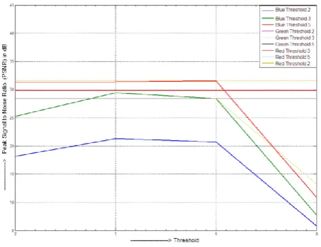
Daubechies filter coefficients are used and 2-level of decomposition is performed, for discrete wavelet transform. For the better analysis of a signal, we should select our ‘mother wavelet’ carefully. Mother wavelet will not only determine how the original signal is well-estimated in terms of translation and dilation, but also, it will affect the frequency spectrum of the signal. The choice of mother wavelet can be based either on the cumulative energy over some interval of interest or based on similarity between original and reconstructed signals. We choose to select the mother wavelet based on the similarity. For this purpose, PSNR is calculated between original and reconstructed image and that mother wavelet is chosen which gives the maximum PSNR. The below figure (12), represents the graph between PSNR in dB and threshold values.
The PSNR is calculated between original video red frames and embedded video red frame. And this is done for blue and green frames of original and embedded video frames at different threshold values and of different videos.
Fig12: Graph between PSNR in dB and threshold values.
This graph for different frames are drawn by using the below table 1of PSNR values.
REFERENCES
[1] Bhatnagar G and Raman B 2010 Distributed multiresolution discrete Fourier transform and its application to watermarking. Int. J. Wavelets, Multiresolution and Information Processing 8(2): 225–241
[2] Cox I, Miller M, Bloom J, Fridrich J and Kalker T 2007 Digital watermarking and steganography. San Francisco, CA, USA: Morgan Kaufmann Publishers Inc.
[3] Doerr G and Dugelay J L 2003 A guide tour of video watermarking. Signal Processing: Image Communication 18(4): 263–282
[4] Ge Q, Lu Z and Niu X 2003 Oblivious video watermarking scheme with adaptive embedding mechanism. Proc. Int. Conf. Machine Learning and Cybernetics, Xian, China 5: 2876–2881 [5] Hsu C T and Wu J L 1998 A DCT-based watermarking for
videos. IEEE Transactions on Consumer Electronics 44(1): 206– 216
[6] Joumaa H and Davoine F 2005 Performance of an ICA video watermarking scheme using informed techniques. Proc. IEEE Int. Conf. Image Processing, Genoa, Italy 1: 261–264
[7] Kong W, Yang B, Wu D and Niu X 2006 SVD based blind video watermarking algorithm. Proc. Int. Conf. Innovative Computing, Information and Control, Beijing, China 1: 265–268
[8] Liu H, Chen N, Huang J, Huang X and Shi Y Q 2002 A robust DWT-based video watermarking algorithm. Proc. IEEE Int. Sym. Circuits and Systems, Scottsdale, Arizona 3: 631–634
[9] Sun J and Liu J 2004 Data hiding with video independent components. IEEE Electronics Letters 40(14): 858–859
[10] Tsai H M and Chang L W 2004 Highly imperceptible video watermarking with the Watson’s DCT-based visual model. Proc. IEEE Int. Conf. on Multimedia and Expo, Taipei, Taiwan 3: 1927–1930
[image:6.595.317.549.197.375.2]International Journal of Emerging Technology and Advanced Engineering
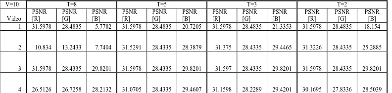
[image:7.595.102.498.160.254.2]Website: www.ijetae.com (ISSN 2250-2459,ISO 9001:2008 Certified Journal, Volume 3, Issue 5, May 2013) Table 1
PSNR values between original watermark image and extracted image frames.
V=10 T=8 T=5 T=3 T=2
Video PSNR [R]
PSNR [G]
PSNR [B]
PSNR [R]
PSNR [G]
PSNR [B]
PSNR [R]
PSNR [G]
PSNR [B]
PSNR [R]
PSNR [G]
PSNR [B] 1 31.5978 28.4835 5.7782 31.5978 28.4835 20.7205 31.5978 28.4835 21.3353 31.5978 28.4835 18.154
2 10.834 13.2433 7.7404 31.5291 28.4335 28.3879 31.375 28.4335 29.4465 31.3226 28.4335 25.2885
3 31.5978 28.4335 29.8201 31.5978 28.4335 29.8201 31.597 28.4335 29.8201 31.5978 28.4335 29.8201
4 26.5126 26.7258 28.2132 31.0705 28.4335 29.4607 31.1598 28.2289 29.4201 30.1695 27.8336 28.5039
AUTHOR’S PROFILE
Mr. D. Hari Hara Santosh obtained his B. Tech. and M. Tech degrees from JNT University, Hyderabad in the year 2005 and 2010. Presently he is pursuing Ph.D, in Video Processing at JNTU, Hyderabad. He is working as Assistant Professor in MVGR College of Engineering, Vizianagaram, AP. He has 7 publications in both International and National Journals and presented 19 papers at various International and National Conferences. His areas of interests are Image Processing, Speech processing and Video Processing.
Mr. Naveen Kumar Sarva obtained his B. Tech. and M. Tech degrees from JNT University, Hyderabad in the year 2005 and 2010. He is working as Associate Professor in MLR College of Engineering, Hyderabad. His areas of interests are Image Processing, Speech processing and Video Processing.
Ms. G. Lakshmi Sunitha is currently pursuing her B. Tech. in MVGR College of Engg., JNT University, Kakinada, Andhra Pradesh. Her areas of interests are Image Processing and Speech processing.