ART DESIGNER QUICK REFERENCE
To use any tool or function, select it. Move any cursor over the icon or function label you want to select and press the
Mark button.
Tools
CIRCLE draws circles and ovals.
CONNECTED LINE draws objects composed of line segments.
CONNECTED LINE REPLACE changes the shape of an object by replacing a part of the object with a newly-drawn connected line.
CONNECTED MOVE pulls and twists an object without separating the original points.
~ COpy duplicates an object.
~
818
1 / HIGHLIGHT shows what object is currently picked. - ~ - Highlight displays a picked object simply as an/ 1 \ outlined figure, without any fill or color.
PICK identifies performed on. is operational.
the object a task will be A hand cursor appears when Pick
SCALE AND MOVE moves objects from one part of the screen to another or proportionally changes the size of objects.
SCULPT allows you to change the shape of an object in much th{j same way a potter shapes clay, by molding and smoothing portions of its shape.
SKETCH draws objects consisting of unsegmented or "smooth" lines.
SKETCH REPLACE changes the shape of an object by replacing a part of an object with a newly drawn sketched line.
~ SQUARE draws squares and rectangles.
FWlctions
ICancel1
IClear
I
Files
IGo
I
IRedrawl
I
Set Up
I
CANCEL interrupts an operation in progress.
CLEAR removes all drawings and text from the active work area.
Selecting FILES displays a menu that allows you to select the Save Chart Format, View Files, Get Picture, Save Picture or Set Default Directory functions.
Select GO to enter text and execute functions.
Select PRINT when you want to print a drawing or chart to an output device.
RED RA W "cleans" holes and gaps left when you have moved objects on the screen. It also reflects the correct order in which objects are overlaid.
I
Tools
lUnda
Izoom
The TOOLS function displays a menu that gives you access to the Chart, Drawings, and Text Tools menus.
UNDO restores the last deleted object to the screen.
ZOOM zooms in on the portion of the work area you choose.
Specifications Subject to Change.
Convergent Technologies and NGEN are registered trademarks of Convergent Technologies, Inc.
Art Designer, Chart Designer, Convergent, CT-DBMS, CT-MAIL, CT-Net, CTIX, CTOS, DISTRIX, Document Designer, The
Operator, AWS, CWS, IWS, MegaFrame, MightyFrame, MiniFrame, MiniFrame Plus, Multibus,
Voice/Data Services, Voice Processor,
and X-Bus are trademarks of Convergent Technologies, Inc.
IBM is a registered trademark of International Business Machines Corporation.
Microsoft, MS, GW, and XENIX are trademarks of Microsoft Corporation.
UNIX is a trademark of Bell Laboratories.
First Edition (July 1986) 09-01134-01
Copyright © 1986 by Convergent Technologies, Inc., San Jose,
CA. Printed in USA.
CONTENTS 1 2 3 IN'TRODUCTION •••••••••••••••••••••••••••••••• OVERVIEW ••••••••••••••••••••••••••••••••••••• 1-1 1-1 WHAT YOU NEED... 1-2 BEFORE USING THIS MANUAL... 1-3 HOW TO USE THIS MANUAL ... 1-4 HOW THIS MANUAL IS ORGANIZED... 1-4 FOR CHART DESIGNER USERS... 1-6 CONVENTIONS USED... 1-6 RELATED DOCUMENTATION... 1-7
STARTING OUT •••••••••••••••••••••••••••••••• . 2-1 SIGNING ON TO THE SySTEM... 2-1 STARTING ART DESIGNER 0 . 0 . . . 0 0 • • 0 0 • • • • • • • 0 . . 2-1
Through the Context Manager... 2-2 Through the Executive... 2-3 THE KEYBOARD •• 0 • • • • • • • • • • • • • • • • • • • • • • • • • • • • 2-5
THE MOUSE •••••••••••••••• 0 • • • • • • • • • • • • • • • • 0 . 2-6
THE ART DESIGNER SCREEN •••••••
0...
2-7 MENUS ••••• 0 • • • • • • • • • • • • • • • • • • • • 0 • • • • • 0 0 0 • • • • • 2-9Selecting Tools and Functions • 0 • • • • • 0 • • • • • • 0 • • 2- 9
The Function Menu •••••••••••••••.••••• 0 • • • • • 2-10
Pop-up Menus •••.••••••••••••
0
.. 0...
2-11 The Tools Menu. 0 • • • • • • • • • • • • 0 • • • 0 • • • • • • 0 . . 2-12THE WORK AREA.o •••• 0 . 0 • • • 0 • • 0 . . . 2-13
Changing Work Areas 0 • • • • • • • • • • • • • • • • • • • • • • • 0 2-14
The Dual Work Area ...
0
... 0...
2-15 SUMMARY.o •••••••••••••••••••••0...
2-17BASIC TECHNIQUES •• 0 • • • • • • • • • • • • • • • • • • • • • • • • •
DRAWING A SIMPLE FIGURE 0 • • 0 • • 0 • • • • • • • 0 • • • •
Squares and Circles ... 0 • • • • • • 0 • • • • • • • • • 0 • • 0 • • •
Clearing the Work Area ... 0 0 0 0 0 0 0 0 0 0 0 0 0 0
WORKING WITH OBJECTS •• 0 • • • • • 0 • • • • • • • • • • • • •
3-1 3-1 3-1 3-4 3-4 PICKING OBJECTS ••• 0 • • 0 • • • 0 • • • • • • • • • • • • • • • • • • 3-7
Picking More Than One Object •••• 0 • • • • • • • • • • • 3- 9
Picking an Object Without Selecting
UNPICKING OBJECTS ••• _... 3-11 BASIC TOOLS... 3-12 FILES ••• _... 3-14 Saving Pictures • _. •• • • • • • • • • • ••• • • • • • • • • • • • •• 3-15 Retrieving Pictures... 3-16 Viewing Files •••• • • • • • • • • • • • • • • • • • • • • • • • • • • • • 3-17 Changing the Default Directory. _. • • • • • • • • . •• • 3-21 SUMMARY. • • • • • • • • • • • • • • • • • • • • • • • • • • • • • • • • • • • • 3-22
4 WORKING WITH CHARTS... 4-1 CREATING A GRAPH FROM MULTIPLAN
5
6
WORKSHEET. • • • • • • • • • • • • • • • • • • • • • • • • • • • • • • • • • • 4-1 SAVING A GRAPH TO DISK... 4-5 RETRIEVING A GRAPH FROM DISK... 4-5 THE CHART TOOLS MENU ••••••••••••••••••••• 4-6 MODIFYING GRAPHS... 4-7 THE GRAPH AS AN OBJECT ••••••••••••••••••• 4- 8 WORKING WITH DIFFERENT TYPES
OF GRAPHS... 4-8 Bar/Stacked Bar Graph ._... 4-9 Line Graphs • ••• • • • • • • • • • • • • • • . • • • • • • • • • • • • • . • 4-10 Axes Menus ••••• 0 0 • • • • • • 0 • 0 • • • • 0 • • • 0 • • • 0 • • • • • 4-11
PIE/EXPLODED PIE ••• _ •• 0 • • • • 0 0 • • • • • • 0 • • • 0 . 0 . . 4-14
SAVING THE CHART FORMAT 0 . 0 • • • • • 0 . . . 4-16
SUMMARY.o •••••• 0 0 • • • • • 0 0 o. 0 0 o. 0 • • • 0 • • 0 • • 0 0 . 0 4-17
WORKING WITH TEXT 0 • • 0 • • 0 0 • • 0 • • • • • • 0 0 • • 0 0 • • • 5-1
PLACING AND JUSTIFYING TEXT • 0 0 • 0 0 • • • 0 • • • 0 5-2
ENTERING TEXT. 0 . 0 ' • 0 • • • • 0 • • • 0 • • 0 ' • • o ••• 0 0 • • • 5-3
CHOOSING THE SIZE AND FONT •• 0 . ' 0 • • • 0 • • • • 0 5-4
MODIFYING TEXT 0 • 0 0 0 • • 0 0 • 0 0 • • • 0 • • 0 • • 0 0 • • 0 0 • • 0 5-5
STRETCHING TEXT 0 0 ' _ 0 • • 0 0 0 • 0 0 0 • 0 • • 0 • • 0 • • • • • 0 5-6
SUMMARY 0 • • 0 0 0 • • o. 0 0 o. 0 . 0 • • • 0 0 • • 0 . 0 0 • • 0 • • • 0 0 . 5-7
WORKING WITH DRAWINGS 0 " . 0 • • 0 • • • • • • • • • • • 0
PLANNING YOUR DRAWING. 0 • • • 0 0 • • 0 • • 0 • • • 0 • 0 0
TOOLS 0 0 • • • 0 0 • • • 0 • 0 0 • • 0 • • 0 • • • 0 • • • • 0 • • • • • 0 • • • • 0
6-1 6-1 6-3 Drawing Tools 0 • • • 0 0 . 0 • • 0 0 • • 0 • • 0 • • 0 0 • • 0 • 0 • 0 0 • 6-3
PLANNING FOR PRINTING 0 " . ' " 0 0 • 0 0 • • 0 0 • • 0 o. 6-6
7
8
9
10
11
ADVANCED TIPS ••••••••••••••••••••••••••••••• USING THE GRID ••••••••••••••••••••••••••••••
7-1 7-1 Grid Snap ... 7-3 USING ZOOM... 7-5 SUMMARY. • • • • • • • • • • • • • • • •• • • • • • • • • • • • • • • • • • • • 7-7
PRINTING ... . 8-1 PRINTING YOUR DRAWING... 8-1 U sing a Plotter ..•....••••..•••...•.•...••••• 8- 2 Using a Laser Printer ... 8-4 Using a Dot Matrix Printer... 8-5 Printing a Portion of a Drawing... 8-5 PRINTING TO SPOOLED OUTPUT DEVICES... 8-5 SUMMARy... 8-6
THE UNEXPECTED ••••••••••••••••••••••••••••• STATUS MESSAGES ••••.•••••••••••••••••••••••• ABNORMAL SYSTEM TERMINATION •••••••••••••
SYSTEM ADMINISTRATION •••••••••••••••••••••• USING THE ART DESIGNER WITH CONTEXT MANAGER ••••••••••••••••••••••••••••••••••••• INTERFACING WITH EXTENDED MULTIPLAN •••• INTERF ACING WITH DOCUMENT DESIGNER ••••• USER CONFIGURATION FILE ••••••••••••••••••• PRINTER CONFIGURATION ••••••••••••••••••••• FILE NAME EXTENSIONS •••••••••••••••••••••••
REFERENCE ••••••••••••••••••••••••••••••••••• 9-1 9-2 9-7 10-1 10-1 10-1 10-2 10-3 10-5 10-6 11-1
APPENDIX A: THE PICTURE LmRARY •••••••••••••• A-I
GLOSSARY ••••••••••••••••••••••••••••••••••••••••• G-l
LIST OF FIGURES Figure 1-1. 2-1. 2-2. 2-3. 2-4. 2-5. 2-6. 2-7. 2-8. 2-9. 2-10. 2-11. 2-12. 3-1. 3-2. 3-3. 3-4. 3-5. 3-6. 3-7. 3-8. 3-9. 3-10. 3-11. 3-12. 3-13. 4-1. 4-2. 4-3. 4-4. 4-5. 4-6. 4-7. 4-8. 4-9. 4-10.
Art Designer and Chart Designer ••.•••••.••.
The Context Manager Screen ••••••••••.•••.. The Executive Command Line •••••.•••.••••• The Art Designer Screen ••••.••••••••.••••. The Keyboard .•••••••••••••••••••.••••.•••• The Mouse •.•••••••••••••••••••••••••••••• The Art Designer Screen •••••••••.••••••••• The Function Menu •••••••••••••••••••.••••• The Tools Pop- Up Menu •••.•••••••••••••••• The Tools Menu ••..••..•.•••.••••••••••.••. The Picture Tabs •••••.•••.••••••.•••.••••. Changing Work Areas .••.•••..•••••••••••••• The Dual Work Area ••.•••••.••••••••.•••••
The Square Icon ..••••••••••.•••••••••••••. Moving the Cursor Diagonally .••••.•••••••.• A Confirmation Menu ••••••••••••••••.••••. A Building Made of Squares •••.•••••••••••.• The Pick Icon and the Hand Cursor •••.••••• Picking an Object •••••••••.••••••••••••••••• A Picked Square and a Picked Circle •••••••• Picking Several Objects at Once ••.•••••••.• The Unpick Icon .••.•..•.••••.•••.••..••••• The Files Pop- Up Menu •••••.••••.•••.••••• The Text Entry Line •.••••••••••.•••••.•••. Viewing Files ••••••••••••••••••••.••••••••. The Temporary Viewing Area •••••••••.•••••
The SalesByRegion Worksheet •••••••••..•••• The Sales By Region Pie Chart •••••••••.••.•. The Chart Tools Menus ••••••.••••.••••••••• Comparative and Stacked Bar Graphs •••••••. The Chart Grid ••••••••••.•.•••••••••.••••• Blank Cells and Broken Lines ••••••••••••••• The X and y-Axes ••••••••••••••••••..••••• Axes Menus for Line and Bar Charts •••••••• Pie and Exploded Pie Graphs •••••••••••••••. An Autosorted Pie Graph •••••••••••••••••••
vi Art Designer: Charts and Drawings
LIST OF FIGURES Figure 5-1. 5-2. 5-3. 5-4. 6-1. 6-2. 6-3. 6-4. 6-5. 6-6. 7-1. 8-1. 8-2. 8-3.
The Text Tools Menu ••••••••••••••••••••••• Left, Center, Right Justification •••••••••••• Fonts ••••••••••••••••••••••••••••••••••••• Scale and Move ••••••••••••••••••••••••••••
The Drawing Tools Menu ••••••••••••••••••• Objects Drawn with Connected Line ••••••••• Twisting an Object with
Connected Move ••••••••••••.•••••••••••••• Modifying an Object by
Replacing a Line ••••••••••••••••••••••••••• Overlaid Filled Objects
in the Work Area •.•••••••••••••••••••••••• Overlaid Filled Objects
Plotted Out •••••••••••••••••••••••••••••••
The Grid (Size 3) ••••••••••••••••••••••••••
The Print Menu •••••••••••••••••••••••••••• Numbered Color Palette •••••••••••••••••••• Laser Printer Line Types •••••••..••••••••••
LIST OF TABLES
3-1. Art Designer Tools •••••••••••••••••••••••••
INTRODUCTION
OVERVIEW
The Art Designer is a powerful software package that turns your workstation into an artist's tool. Using the Art Designer, you can
• create charts and graphs from Extended Multiplan worksheets
• draw original illustrations on your workstation screen
• customize your chart or drawing by adding colors, fill patterns, and different line types
• add different styles and sizes of text
• copy, stretch, move, .enlarge, and reshape charts and drawings
• save what you create on a disk for future use
• print out charts and drawings on a plotter, laser printer, or dot matrix printer
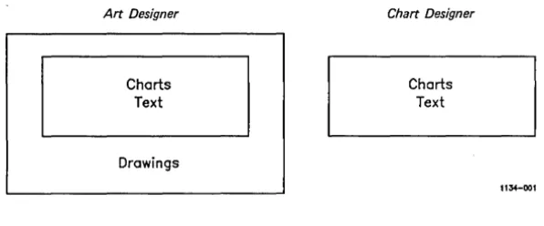
The Art Designer has two major capabilities: it allows you to create and modify drawings and graphs. That portion of the Art Designer that enables you to create and modify graphs can be purchased as a separate program called the Chart Designer.
Art Designer
Charts Text
Drawings
Chart Designer
Charts Text
Figure 1-1. Art Designer and Chart Designer
l1~OOl
You can create original drawings on your workstation screen using the Art Designer. The Chart Designer is part of the Art Designer; it works with Extended Multiplan to create line, bar, and pie charts.
Both programs, when packaged together, are simply called the Art Designer. Remember that the Chart Designer features are wholly combined within the Art Designer.
The Chart Designer is sold separately from the Art Designer. You may only have the Chart Designer. If this is the case, or if you are not sure if you have both programs, see the note to Chart Designer users below.
WHAT YOU NEED
To create charts with the Chart Designer, you must use data from an Extended Multiplan worksheet. Therefore, you need to have Extended Multiplan installed on your workstation. However, you do not need Extended Multiplan to create drawings with the Art Designer.
[image:15.435.33.331.48.172.2]If you have the Document Designer installed on your work-station, you can integrate charts and drawings with documents. See Getting Started: Integrating Objects in the Document Designer for more information.
If your workstation has not already been set up so that the Art Designer interfaces with Extended Multiplan or Document Designer, consult your system administrator or see Chapter 10 of this manual.
BEFORE USING THIS MANUAL
This manual is designed to be used with the Getting Started with Charts and Getting Started with Drawings booklets. They provide a step-by-step introduction to many of the Art Designer's features.
If you have not worked through these booklets, do so now. They prepare you for the information presented in this manual.
To find information quickly, use the Reference section. To refine your technique, study the Concepts section.
HOW TO USE THIS MANUAL
You do not need to read through this entire manual before you can start using the Art Designer. In fact, if you have gone through the Getting Started booklets, you already have some basic knowledge.
To get started with the Art Designer:
1. Work through the Getting Started booklets.
3. Use the Art Designer and look up anything you don't understand in the Reference section. Most basic questions are answered in the Reference section.
4. Use the other chapters as you need them. Each chapter describes how to perform a specific task with the Art Designer. For example, to print out your drawing, see Chapter 8. If you want to add text to a chart, see Chapter 5.
HOW THIS MANUAL IS ORGANIZED
This chapter, "Overview," provides a general description of the Art Designer and its features, and explains how to use this manual.
Chapter 2, "Starting Out," describes the fundamental components of the Art Designer software.
Chapter 3, "Basic Techniques," describes how to use the different features of the Art Designer, including how to save, store, and retrieve the drawings you create.
Chapter 4, "Working with Charts," explains how graph data is created in Extended Multiplan, and is transferred to the Chart Designer. It also describes how to use the Chart Tools menu to modify and create bar, line, and pie graphs.
Chapter 5, "Working with Text," describes how to enter and edit text in a drawing or chart.
Chapter 6, "Working with Drawings," describes the drawing tools and how to use them to create drawings. It also discusses how to plan your drawing and what to consider before you print.
Chapter 7, "Advanced Features," explains how to use advanced features, including Grid and Zoom.
Chapter 8, "Printing," describes printing techniques for printing a chart or drawing on a plotter, laser printer, or dot matrix printer.
Chapter 9, "The Unexpected," provides some solutions to typical problems you may encounter when you use the Art Designer, including error codes, the cause of the error, and appropriate resolutions.
Chapter 10, "System Administration," provides technical information for the system administrator.
Chapter 11, "Reference," presents, in alphabetical order, descriptions of each feature in the Art Designer.
Appendix A, "The Picture Library," is a collection of pictures that is included with the Art Designer.
A quick reference card is also provided with this manual.
FOR CHART DESIGNER USERS
This manual describes both the Art and the Chart Designer. If you have the Chart Designer only, simply skip over the information that does not pertain to you.
Many of the features are the same in both programs. Parts of Chapter 3 and all of Chapter 6 discusses features not applicable to the Chart Designer. The other chapters discuss features common to both programs.
CONVENTIONS
Throughout this manual, the following conventions are used:
When an important concept or useful technique is introduced, a "Key Idea" or "Hint" box like this appears:
r---HINT---~
Complete the Getting Started booklets before beginning the next chapter.
The names of Art Designer tools and commands are capitalized.
Example:
Use the Connected Line tool to draw a straight line.
The names of keyboard keys and words that appear on the workstation screen appear in boldface type.
Example:
Select Save Chart Format on the screen, type in the file name, and press Go.
Important terms introduced for the first time are underlined and defined in the Glossary.
Example:
You select icons to use ~.
RELATED DOCUMENTATION
The documents described below provide additional information related to the contents of this manual.
For a complete list of Convergent Technologies publications, see the "Guide to Technical Documentation" in the Executive Manual or similar command-line interpreter manual for your operating system.
Introductory
Context Manager Manual Executive Manual Status Code Manual
Operating Systems
eTOS Operating System Manual
Office Automation
Document Designer Reference Manual Extended Multiplan User's Guide Extended Multiplan Reference Manual Getting Started
Mouse Services Manual
Communications
Asynchronous Terminal Emulator Manual
The Context Manager \1anual describes and teaches the use of the Context Manager, which allows the user to run applications concurrently and interchange them on the screen almost instantly.
The Status Codes Manual contains complete listings of all status codes, bootstrap ROM error codes, and CTOS initialization codes. The codes are listed in numerical order along with any message and an explanation.
The CTOS Operating System Manual describes the CTOS operating system. It specifies services for managing processes, messages, memory, exchanges, tasks, video, disks, keyboard, printer, timer, communications, and files. In particular, it specifies the standard file access methods: SAM, the sequential access method; RSAM, the record sequential access method; and DAM, the direct access method.
The Document Designer Reference Manual is a reference tool for users of the Document Designer. The manual discusses the capabilities of the Document Designer and describes in detail each of its commands. Information is included on integrating application systems with the Document Designer, generating automatic tables of contents, including voice annotations in documents, list processing, text manipulation, and system configura tion.
The Extended Multiplan User's Guide introduces the new user to the spreadsheet program.
The Extended Multiplan Reference Manual is a reference tool for users already familiar with Extended Multiplan. It describes the Multiplan keyboard and screen, both basic and advanced operations, and printer configuration. Complete directories of all commands and functions are included.
The Getting Started booklets that accompany this manual provide a simple way to start using Art Designer and Chart Designer quickly.
The Mouse Services Manual describes the Mouse Server. It is directed toward programmers, but also contains some information for the end user.
The AsynChronous Terminal Emulator Manual describes the asynchronous terminal emulator.
2 STARTING OUT
Before you can become an expert with the Art Designer, you must learn the fundamentals. This chapter introduces the fund-amental components and concepts of the Art Designer program.
When you finish this chapter, you will know how to
• invoke the Art Designer program
• use the keyboard and the Mouse
• select tools from a Tools menu
• use the Function menu
• work in the work area
• change work areas
SIGNING ON TO THE SYSTEM
To sign on to your workstation, you must complete the SignOn form. Your system administrator can help you if you do not know your user name or password. The SignOn form is explained in detail in the Executive Manual.
STARTING THE ART DESIGNER
You can invoke the Art Designer program in two ways:
• through the Context Manager
THROUGH THE CONTEXT MANAGER
If you have the Context Manager on your workstation, display the Context Manager screen by pressing the Action key and the Go key simultaneously, as shown in Figure 2-1.
status Contexts you can return to
I
Applications you can startArt Designer Document Designer Executive Extended Multiplan Logout Mail
Select application. optionally choose function key. then press GO.
Figure 2-1. The Context Manager Screen
1135-001
The Context Manager screen may not appear exactly like the one shown in Figure 2-1. It should, however, have the words Art Designer or Chart Designer displayed in the selection menu. (If it doesn't, see your system administrator.)
To invoke the Art Designer:
1. Use the Arrow keys to move the highlight cursor to the words Art Designer.
2. Press Go.
THROUGH THE EXECUTIVE
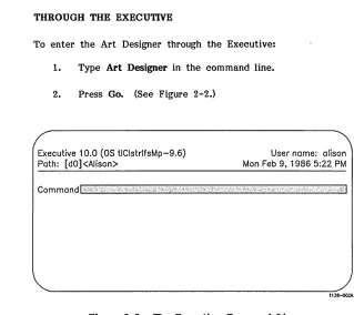
To enter the Art Designer through the Executive:
1. Type Art Designer in the command line.
2. Press Go. (See Figure 2-2.)
Executive 10.0
(as
tIClstrlfsMp-9.6) Path: [dO]<Alison>User name: alison Man Feb 9, 1986 5:22 PM
lIJ~
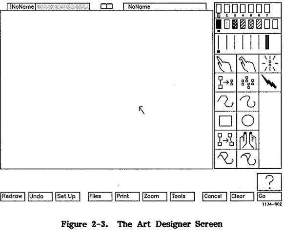
[image:24.432.82.401.48.332.2]An arrow appears briefly on the screen while the Art Designer is loading; then the Art Designer screen is displayed, as shown in Figure 2-3. To use the Art Designer screen, you need to know how to work with the keyboard and the Mouse.
IINoNamel,;,;\,,;;',;,c v , ; I CO I NoNa me I
JQQQQQQ
'DI~~rgDD
I II I I II
•
h
h
\1/- ~
-11\
6-
H ~~ ~ 8"
'\
0w
~
D
0
6~b
~~
"'0
~
Figure 2-3. The Art Designer Screen
[image:25.432.33.324.134.376.2]THE KEYBOARD
The keyboard on your workstation is similar to a typewriter keyboard. It has letter and number (alphanumeric) keys that you use to enter text. (See Figure 2-4.)
I \ Co
7 II II
1
I-~ I Next
1 2 3
0
Figure 2-4. The Keyboard
The keyboard also has a top row of ten function keys, labeled FI through FlO. You will use these keys to execute certain Art Designer commands. (See the discussion about the Function menu below for more details.)
The Finish key, in the lower-left corner of the keyboard, is used to exit the Art Designer. When you want to end a ses-sion, press Finish.
The Go key is used to complete certain tasks.
To practice using the Arrow keys:
1. Hold down the Shift key.
2. Press the appropriate Arrow key to move the cursor around the screen.
Notice that the arrow cursor displayed on your screen moves around rather slowly. For this reason, it is much easier and more efficient to use a Mouse to move the cursor in the Art Designer.
THE MOUSE
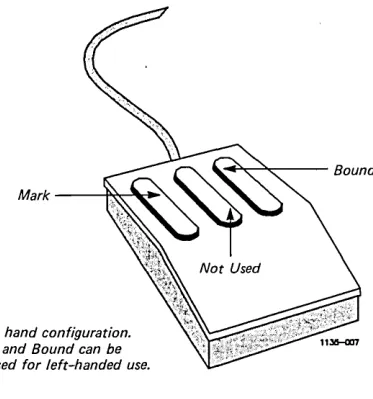
The Art Designer is best used with a small pointing device called a Mouse, as shown in Figure 2-5. By moving the Mouse on your desktop, you move the cursor on the screen.
The Mouse has three buttons, but the Art Designer requires that you use only the first and third buttons (see Figure 2-5).
The first button corresponds to the Mark key on your keyboard. The third button corresponds to the Bowd key. The middle button is not used.
If the Mouse is not already installed, plug it into one of the two ports on the back of your keyboard. (The other port con-tains the cord that links your keyboard to the video display terminal.) See the Mouse Services Manual for further details on connecting the Mouse to your keyboard.
(The Mouse is set up for right-handed use. If you are left-handed, you can change the Mouse so that you can use it more easily. See "Mouse Hand" in the Reference section for details.)
Right hand configuration. Mark and Bound can be reversed for left-handed use.
~~---Bound
Figure 2-5. The Mouse
THE ART DESIGNER SCREEN
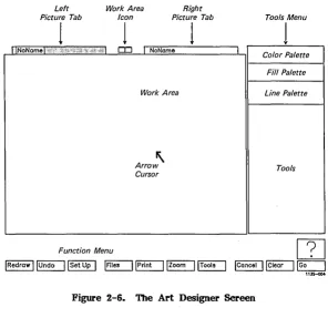
The Art Designer screen has two main areas (as shown in Figure 2-6):
• the Work Area
• the Tools menu
You create drawings in the Work Area with tools you select from the Tools Menu.
A tool is a feature you use to perform a task, such as drawing a circle, deleting an object, or copying an object in the work area.
[image:28.433.168.355.56.256.2]Left Picture Tab
1
L1NoNome I "'c"
Work Area Icon
1
Right Picture Tab
1
CD I NoNome
Work Area
"
Arrow Cursor
Tools Menu
1
I Color PaletteFill Palette
Line Palette
Tools
Function Menu
rn
IRedrawl~lsetup I ~~IZoom I~ IConcel I~~
Figure 2-6. The Art Designer Screen
Other parts of the screen include the following:
• The Picture Tabs display the name of the current chart or drawing.
• The Work Area Icon is used to switch between single and dual work areas.
• The Text Entry Line is where text is typed.
• The Function menu items correspond to the function keys (FI through FlO) on your keyboard.
2-8 Art Designer: Charts and Drawings
[image:29.434.32.329.50.338.2]Each part of the Art Designer screen is discussed in detail later in this chapter, except for the text entry line, which is discussed in Chapter 3.
MENUS
A ~enu in the Art Designer is similar to a menu in a res-taurant; it lists the selections available to you.
Two menus are always displayed whenever you are in a work area:
• the Function menu
• the Tools menu
-To activate a selection on one of these menus, you must select it.
SELECTING TOOLS AND FUNCTIONS
To select a tool or function:
1. Move the arrow cursor to the icon you want to select.
2. Press, then release, the Mark button. (This is called clicking the button.)
The selected icon is highlighted, which means it displays brighter.
~---KEY IDEA---~
(If you are not using a Mouse, select a tool or function by pressing the Mark button on the keyboard.)
Try selecting an icon on the Tools menu by moving the cursor directly over an icon and clicking the Mark button. The icon is then highlighted. Click the Mark button again; the highlight disappears.
THE FUNCTION MENU
The Function menu appears along the bottom of the screen and contains ten boxes, called labels, that correspond to the function keys (Fl through FlO) on your keyboard. (See Figure 2-7.)
Figure 2-7. The FtDlction Menu
To use a function, select its label on the Function menu; the label has the function name in it. You can also use a function by pressing the corresponding key on the top row of the keyboard.
POP-UP MENUS
Some functions have ~ ~ associated with them. A pop-up menu appears when you select the function label. You then make an appropriate choice from the pop-up menu. For example, to make a choice from the Tools pop-up menu:
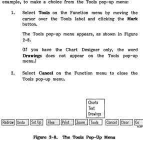
1. Select Tools on the Function menu by moving the cursor over the Tools label and clicking the Mark button.
The Tools pop-up menu appears, as shown in Figure 2-8.
(If you have the Chart Designer only, the word Drawings does not appear on the Tools pop-up menu.)
2. Select Cancel on the Function menu to close the Tools pop-up menu.
Charts Text Drawings
IRedrowllUndo
IISet
UpI
~ IPrint •I I
ZoomI I
ToolsI
ICancelllClearI
~1134-004
Figure 2-8. The Tools Pop-Up Menu
Selecting the Cancel label on the Function menu removes any pop-up menu from the screen.
From the Tools pop-up menu, you can select a Tools ~. Tools menus are discussed below.
Other functions on Chapter 3. Each Reference section.
the Function menu function is described
are discussed in detail in
[image:32.437.108.395.118.418.2]The Tools Menu
The Tools menu is located on the right side of the Art Designer screen. It contains icons representing the various tools that you can use to create charts and drawings.
A tool is selected from a Tools menu. A function is selected from the Function menu.
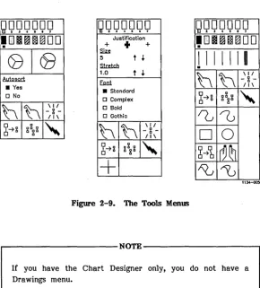
Three different Tools menus exist, containing tools for Charts, Text, and Drawings. (See Figure 2-9.)
QQQQQQO
OQQQOOQ
QQQQQQO
.DI~~~DD
.
Justificotion+
+
+ .DI~flll~DD.
<BI~
~
• Yes
o No
h
h
-
\11 ~-11\
~
5 t
'"
S1mt.c.b
1.0
t '"
8ml • Standard
o Complex
o Bold
o Gothic
I I I I III
.
h
h
- & -\1111\
6
4 & && &"
&
~
~
64~ && &
"
&
h
h
\ I I
&
-11\
D
0
64~ g ~ g
"
&
+
6
1\0
4b
~~
"D
1134-00:1Figure 2-9. The Tools Menm
~---NOTE---~
If you have the Chart Designer only, you do not have a Drawings menu.
[image:33.435.36.326.203.524.2]To choose a particular Tools menu:
1. Select Tools on the Function menu.
A small menu pops up with the names of the Tools menus on it.
2. Move the cursor over the name of the menu you want to display.
3. To select the menu, click the Mark button on the Mouse.
The Tools menu displays on the right side of the screen.
Now display each of the Tools menus available to you. Each tool on each menu is discussed in the following chapters and in the Reference section.
THE WORK AREA
The work area is the "blank canvas" where you create charts and drawings. You cannot draw anything outside of the work area.
If you try to draw a figure that goes beyond the borders or use a tool outside the work area, an error message appears and your action is ignored.
~---HINT---~
CHANGING WORK ARBAS
A t the top of the work area are two boxes, called picture tabs, with the names of picture files in them. (At this point, these tabs probably both say NoName.) One of the tabs is high-lighted, as shown in Figure 2-10.
NoName '. NoNa me
11~
Figure 2-10. The Picture Tabs
These picture tabs are like tabs on a file folder. Just as a file folder has the name of the file on its tab, the name of the picture file appears on the picture tab.
The highlighted picture tab shows the name of the picture currently displayed on the screen. If you select the other picture tab, that tab is highlighted and its picture is displayed.
The work areas and the respective picture tabs are like two stacked file folders. The tab on top covers the one below it.
When you select a picture tab, the picture it "holds" moves "on top,1f where you can work on it. The picture on top is the active picture and the highlighted picture tab is the active picture tab. (See Figure 2-11.)
A~~
I
Picture Tab --~r-~~!!X!5!!!c=:::::L...t:rnJ:L _ _ _ .-l----,
-Active
1 - - - -Work Area
1134-007
Figure 2-11. Changing Work Areas
The other picture still exists, but it is "covered" by the active picture. By selecting the picture tab, you can switch between the two pictures as often as you like.
THE DUAL WORK AREA
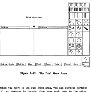
Sometimes you may want to view or work with two pictures at once. You can do this by switching to the dual ~ ~, which displays two drawings side-by-side.
To display the dual work area, select the Work Area icon, which is located between the two picture tabs at the top of the screen. (See Figure 2-10.)
gQQQQQQ
• 0
.
IIIH~H81 ~DD
Work Area Icon
.
I I I I I II
1
h
h
-g-\1111\
NoNa me 1 Cj I; INoName L" 1 ';",>,:;1 ,»,',,';,:::,',','\ ~~g gg g
"
g
10
~
D
0
~~b
~~
1\0
~
Figure 2-12. The Dual Work Area
When you work in the dual work area, you can combine portions of two pictures by copying from one work area to the other. (See "Copy" in the Reference section for more details.)
To return to the single work area, select the Work Area icon.
[image:37.433.37.335.51.353.2]SUMMARY
• You create drawings on the Art Designer screen. It has two main sections: the work area and the Tools menu.
• The Mouse is used to move the cursor around the screen. The Mouse can be set up for left-handed use.
• To use a tool or function, select it by placing the cursor over the appropriate icon or label and clicking the Mark button on the Mouse.
• The Function menu and a Tools menu are displayed when you are in a work area. There are three Tools menus: Charts, Text, and Drawings.
• A pop-up menu is a box that pops up when certain functions are selected. It has various options you can select. Cancel (on the Function menu) dismisses a pop-up menu.
• The Picture Tab shows the name of a picture file. If you select a Picture Tab, that picture displays and becomes active.
3 BASIC TECHNIQUES
This chapter explains how to use some of the tools you need to create and modify charts and drawings.
When you finish this chapter, you will know how to
• draw a simple figure
• identify an object
• pick and unpick an object or group of objects
• use each of the Art Designer's basic tools
• save picture files to a disk
• retrieve picture files from a disk
• change from one directory to another
DRA WING A SIMPLE FIGURE
SQUARES AND CIRCLES
For now, you will learn how to use the most basic drawing tools: the Square and the Circle.
~ Demgner Usen---~
The Chart Designer program does not have any drawing tools, so you won't be able to use the squares and circles in this chapter. Instead, use a letter or group of letters so you can practice what you read. See Chapter 5 to learn how to create text.
To draw a square or rectangle:
1. Select the Square icon on the Drawing Tools menu by moving the cursor over the icon and clicking the Mark button. (See Figure 3-1.)
2. Move the cursor into the work area.
3. Press and hold the Mark button.
4. Drag the cursor diagonally, toward any corner of the screen.
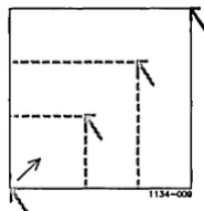
As you drag the cursor, a box "grows" on the screen, as shown in Figure 3-2.
Figure 3-1. The Square Icon
,
---1\
---i\
.\
•
/'
:
«I
I
•
I
•
(
I I
•
1134-00IIFigure 3-2. Moving the Cursor Diagonally
5. Release the Mark button.
A square appears on the screen.
You use the same technique to draw circles or ovals with the Circle tool:
1. Select the Circle icon and drag the cursor diago-nally, toward any corner of the screen.
As you drag the cursor, a box "grows" on the screen.
2. Release the Mark button.
A circle is drawn.
[image:42.435.209.302.47.142.2]CLBARING THB WORK ARBA
After you have drawn several circles and squares, you can clear the work area by selecting Clear on the Function menu. When you do, everything drawn in the work area disappears.
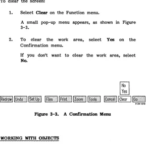
To clear the screen:
1. Select Clear on the Function menu.
A small pop-up menu appears, as shown in Figure 3-3.
2. To clear the work area, select Yes on the Confirmation menu.
[image:43.433.27.320.130.415.2]If you don't want to clear the work area, select No.
Figure 3-3. A Comll"mation Menu
WORKING WITH OBJECTS
When you draw circles and squares in the work area, you create objects. An object is an individual element of a drawing.
The Art Designer is an object-based system. When you perform a task, you work with the entire object, not just a part of it. (The technical name for this type of system is a vector system.)
When you create a drawing with the Art Designer, you assemble it out of individual objects. You can draw a simple picture of a building, for example, using a large rectangle as a facade and small rectangles as doors and windows. (See Figure 3-4.)
DDD
DDD
[image:44.437.192.319.128.230.2]l1J.4-{l11
Figure 3-4. A Building Made of Squares
Now use the Square tool to draw a building similar to the one in Figure 3-4. Don't be concerned if it doesn't look exactly like the building shown in the illustration.
Although the building appears to be a unit, it is actually made up of several separate objects. You can delete or modify parts of a drawing without affecting the rest of the drawing.
To delete a window in the building (or delete any other object):
1. Select the Delete icon on the Tools menu.
A Lightning Bolt cursor appears.
2. Move the Lightning Bolt cursor over the window you want to delete.
3. Hold down the Mark button and move the Mouse in any direction.
A box-shaped cursor appears.
4. Move the Mouse to one side and slightly upward so that the box-shaped cursor drags across an edge of the window.
5. Release the Mark button.
The window is deleted. intact.
Everything else is left
~---KHY IDHA---~
Figures are made up of individual objects. Each object can. be worked on separately.
PICKING OBJECTS
To work with an object, you must pick it. Picking an object identifies it as the one you want to work with. To use some of the tools discussed in this and subsequent chapters, you need to know how to pick objects.
Picking an object is easy to do. Follow these steps:
1. Select the Pick icon (the one with the extended index finger) on the Tools menu.
The Hand cursor appears, as shown in Figure 3-5.
Pick Icon Hand Cursor 1134-012
Figure 3-5. The Pick Icon and the Hand Cursor
2. Move the hand cursor over the object you want to work with.
3. Hold down the Mark button.
4. While holding down the Mark button, move the Mouse to one side and slightly upward.
A box-shaped cursor appears.
113+-013
Figure 3-6. Picking an Object
6. Release the Mark button.
The object is now picked.
If you have not caught the edge of the object with the box cursor, an error message appears and the object is not picked. Repeat the steps above.
When an object is picked, a broken-line box surrounds it, as shown in Figure 3-7.
1 1
1 1
1
1
1
1
1 1 1 1
1 _________________ _
Picked Square Picked Circle
Figure 3-7. A Picked Square and a Picked Circle
1135-027
, . . - - - HINT - - - ,
You pick an object by surrounding it with the box cursor or by dragging the box cursor across an edge of the object.
[image:47.433.51.295.50.274.2]An object remains picked for as long as you choose. This means that you can perform more than one task on a picked object. For example, you can pick an object, change its color, shrink it, and copy it without having to pick the object each time you change tasks.
PICKING MORE THAN ONE OBJECT
You can pick more than one object simultaneously. To work on several objects at once, drag the box cursor across an edge of each object. (It does not matter which edge you choose.) See Figure 3-8.
For example:
1. Use the Circle and Square tools to draw several objects on the screen.
2. Select the Pick icon.
The Hand cursor appears.
3. Hold down the Mark button and drag the box-shaped cursor across an edge of each object. Or surround the objects with the box-shaped cursor. (See Figure 3-8.)
4. Release the Mark button.
The group of objects is picked.,
The Art Designer regards a picked grou- -~ ... ; .... ,. .. ~ ~ft ~ ~;~ . . . . 1 ....
object. You can copy, move, change colors, or perform any other task and the entire group of objects is affected.
PICKING AN OBJECT WITHOUT SELECTING THE PICK ICON
Some of the Art Designer's tools require that you pick an object before you can use the tools. If a tool requires that you pick an object, the Hand cursor appears when you select the icon for that tool. Simply pick the object you want to work with; then continue with your task.
This method of picking will become clearer as you become more familiar with the basic tools introduced later in this chapter. For now, simply remember that selecting the Pick icon is just one way of making the Hand cursor appear.
UNPICKING OBJECTS
When you are finished working with an object, you unpick it. There are three ways to unpick objects:
• Select the Unpick icon.
• Pick another object.
• Use the Botmd button.
When you unpick an object, the box that surrounds it disappears.
If you have selected the Unpick icon to unpick an object, the Hand cursor remains ready to pick another object. (See Figure 3-9.) If you do not want to pick another object, select another tool after you have unpicked the object.
1134-018
Figure 3-9. The Unpick Icon
Selecting the Unpick icon is similar to using a switch on a lamp. When you unpick an object this way you turn Pick off, but you are immediately able to turn
!!
2.!!. again by picking a new object.When the Pick icon is highlighted, you can also unpick an object using the Bound button. Hold down the button, drag the box cursor across the edge of an object, then release the Bound button.
You can also pick a group of objects and· then unpick individual objects within the group. For example, if you want to change the color of a group of objects and copy all but one of them, you would follow these steps:
1. Pick the group.
2. Change the color on the Color Palette.
3. To unpick the object you do not want to copy, use the Bound button and drag the box-shaped cursor across the edge of the object you want to unpick.
You can unpick with the Bound button only if the Pick icon is active.
4. Copy the other objects, which remain picked.
BASIC TOOLS
Now that you know how to pick and unpick an object, you are ready to try some of the Art Designer's tools. Six basic tools appear on each Tools menu. They are shown and described briefly in Table 3-1 below. Each of these tools is discussed in detail in Chapter 11, "Reference."
Table 3-1
ART DESIGNER TOOLS
Tool Icon Description
Pick
[EJ
Identifies the object a task willbe performed on. A hand cursor appears when Pick is operational.
Un pick
[b]
Removes the pick from an object.When you are through working on a picked object, you unpick it.
Highlight
GrJ
Shows what object is currently- g - picked. Highlight displays a picked
/1\ object simply as an outlined figure,
without any fill or color.
Scale and Move
~
Moves objects from one part of thescreen to another or proportionally changes the size of objects.
Copy
~
Duplicates an object.Delete
[SJ
Eliminates an object from thework area.
Connected Une
ru
Draws objects composed ofline segments.
Sketch
rn
Draws objects consisting ofunsegmented or "smooth" lines.
Square
[Q]
Draws squares and rectangles.Circle
[Q]
Draws circles and ovals.Connected Move
~
Pulls and twists an object withoutseparating the original points.
Sculpt
[[ffi
Changes the shope of an object inmuch the same way a potter shapes clay, by molding and smoothing portions of its shape.
Sketch Replace
~
Changes the shape of an object byreplacing a part of the object with a newly drawn sketched line.
Connected Line
ru
Changes the shape of an object byReplace replacing a part of the object with a
Once you create drawings, you will probably want to save them for future use. The Art Designer charts and drawings are saved in picture files on a disk. A picture file is any picture that you give a name and save on a disk.
The Files function manages your picture files. Using the Files function, you can
• save pictures to a disk
• load pictures from the disk into the work area
• list the names of the picture files in your current directory
• display pictures quickly so you can browse through the files on a disk
• change your working directory
When you select the Files icon, a pop-up menu appears, as shown in Figure 3-10.
Set Default Directory Save Chart Format Get Picture Save Picture
View Files
Figure 3-10. The Files Pop-Up Menu
From the Files pop-up menu, select the Files function you want to perform.
SAVING PICTURES
To save a picture to a disk:
1. Select Files on the Function menu.
2. Select Save Picture on the Files pop-up menu.
3. Delete any name that may already be in the text entry line.
4. Type the name of the file you want to save into the text entry line. (See Figure 3-11.)
You may !lse any combination of up to 32 letters and numbers in a file name.
5. To save the picture to disk, select the Go icon.
Type a picture filename and press GO to execute.
1-
IIJ~leFigure 3-11. The Text Entry Line
r---HINT---.
The file name from the active picture tab is automatically entered into the text entry line. If you do not want to work on that file, delete the name and type in the name of the file you want to use.
It is a good idea to save frequently. Any drawing or chart you create becomes a permanent part of the picture file on a disk only when you save it.
If you make changes to a picture you have retrieved from a disk, the old file on the disk is overwritten with the updated version when you save the picture. If you want to keep the original picture, save the edited version under a different name. In this way, both versions are saved on the disk.
By saving frequently during a work session, you will avoid losing all your work if, for any reason, the computer's power goes off. If the unexpected occurs, and the power does go off, you lose only the work you have completed since the last time you saved.
How often should you save? It depends on how much work you are willing to lose. It is probably wise to save every fifteen minutes or so. This way, you never lose more than a few minutes worth of work.
If you end your work session without saving, all your work since the last save will be lost.
RETRIEVING PICTURES
To work on a picture you have previously saved, use the Get Picture function. The picture you get from the disk is displayed in the active work area. (The active work area is the one with the highlighted picture tab.)
To get a picture from the disk:
1. Select Files on the Function menu.
2. Select Get Picture on the Files pop-up menu.
3. Type the name of the file you want to get into the text entry line.
4. To load that picture into the active work area, select the Go icon.
Now, use the above procedure to retrieve the picture file you created when you learned how to save files to the disk.
Getting a new picture clears the work area of any picture that is displayed. Save any picture you want to keep before you load in a new picture.
vmWING FILES
To see the picture files in your directory, use the View Files function. When you select View Files, an alphabetical list of the picture files in your directory is displayed above the temporary viewing~. (See Figure 3-12.)
Arrows 1 Arrows2 ElectronicSymbols 1 Hardware1 MiscSymbols1 Money1 Money2 OfficeOb jects 1 OfficeOb jects2 OfficeObjects3 People1 People2
Previous Page Icon
}
Directory Filenames
Next Page Icon
1I;)4-()20
Figure 3-12. Viewing Files
If the picture file names cannot be contained on one page, use the Next Page and Previous Page icons to move from page to page.
[image:56.437.111.400.210.428.2]This is the best way to get pictures from the disk because you do not need to type the file name when you select it from the directory listing.
To view the contents of a file, select the Preview ~ before you select the picture name. The picture appears in the active screen of the temporary viewing area. (See Figure 3-13.)
Arrows 1 Money2 Arrows2 OfficeObjects1 ElectronicSymbols 1 OfficeObjects2 Hardware1 OfficeObjects3 MiscSymbols1 People1
Money1 People2
Iti~l.-
m
[IDJ
@Q]
lNoName I ." '\ ... / .. ,,',.',.';','::"";>"':.';;)" :". NoName
Preview Icon
llJ4-02M
Figure 3-13. '!be Temporary Viewing Area
The temporary viewing area looks like the dual work area with its side-by-side screen. Note that you cannot work on the pictures"displayed in the temporary viewing area.
To display two pictures side-by-side in the temporary viewing area, select the other picture tab and select the file name from the directory listing.
[image:57.439.30.321.155.402.2]When you want to work on a picture (or pictures) displayed in the temporary viewing area, select the Go icon. The picture is then loaded into the active work area.
If you decide not to work with the files you have previewed, select Cancel on the Function menu (or press F8). The picture that was active before you previewed other files is displayed in the active work area.
Here's an example of how you might use the View Files function:
1. To go into the dual work area, select the work area icon (located between the picture tabs at the top of the work area).
2. Select Tools on the Function menu.
3. Select View Files from the pop-up menu that appears. The list of file names appears.
4. Use the Next Page and Previous Page icons (located below the file names) to page through the directory.
5. To view the files in your directory, select the preview icon.
6. Select the picture tab of the work area in which you want your picture to display.
7. Select the name of the file you want to preview.
The file appears in the new active work area.
8. To preview a file in the other work area, select the other picture tab.
9. Select the name of the file you want to preview.
10. When the files being previewed are the ones you want to work with, select the Go icon.
11. The files are loaded; you are in the dual work area once again.
When you wish to work with one of the pictures in the single work area:
12. Select the picture tab of the picture you want to work with.
13. Select the work area icon between the picture tabs.
Your picture appears in the single work area.
Going into the dual work area before viewing and selecting files allows you to immediately work with both pictures visible as soon as you select Go. However, it is not necessary. You can view and select files from the single work area by following steps 2 through 10, which may be more efficient if you're working with only one picture.
The View Files function provides a simple way to preview and load a picture you want to work with. Practice working with these functions until you feel comfortable.
CHANGING THE DEFAULT DmECTORY
You can view or work with files from another directory by using the Set Default Directory function.
A directory is like a file cabinet for your picture files. Changing directories gives you access to the files in a different "file cabinet."
To change directories, follow these steps:
1. Select Set Default Directory on the Files pop-up menu.
The name of the current volume and directory appears in the text entry line.
2. Delete the old volume and/or directory name and type in the name of the new volume and/or directory.
3. Press Go.
SUMMARY
• When you want to work on an object in your work area, you must first pick it.
• Six tools appear on every Tools menu: Pick, Unpick, Highlight, Scale and Move, Copy, and Delete. .
• Use functions by selecting a label on the Function menu and then selecting from the displayed pop-up menu.
• Save picture files frequently to avoid losing the work you have completed.
• The View Files function displays a list of the picture files in your directory.
• Quickly preview your picture files by displaying them in the temporary viewing area.
• To work in a different directory, use the Set Default Directory function.
4 WORKI NG WITH CHARTS
The Chart Designer uses data from an Extended Multiplan worksheet and translates it into a pie, bar, or line graph. To create a new chart with the Chart Designer, you must have Extended Multiplan installed on your workstation.
This chapter describes the types of charts and graphs available to you and explains how to work with them using the Chart Designer.
CREATING A GRAPH FROM A MULTIPLAN WORKSHEET
A graph can be created only from the data in an Extended Multiplan worksheet. Thus, you must first go into Extended Multiplan to create new graphs. Once you create or load a worksheet, you can go directly from Extended Multiplan to the Art Designer. When you save a graph in Art Designer, you can work with it as you would any other art file.
A sample worksheet called "SalesByRegion" is provided on the Art Designer release diskette (and should be on your computer system currently).
You are now going to create a graph from data in the SalesByRegion worksheet. Before you begin, you should be in the Context Manager.
1. Use the Arrow keys to move the highlight cursor to "Extended Multiplan" and press Go.
A blank worksheet appears.
To load SalesByRegion into Extended Multiplan, invoke the Transfer Load command:
2. Press T, then press L
3. Type [sys)<sys>SalesByRegion
If you make a mistake, press Backspaee to erase the error; then retype.
4. Press Return.
The SalesbyRegion worksheet appears on the screen, as shown in Figure 4-1.
#1 I
1 2 East 3 Midwest 4 t'Jorth 5 West 6 South
7 8 9 10 11 12 13 14 15 16 17 18 19 20 21 I
22 I I
2 1983 23 28 32 33 35 I I 3 1984 32 37 44 38 42 I I 4 1985 38 42 40 44 41 I I 5 1986 41 44 47 49 44 I I
6 I
I
COMMAND: Alpha Blank Copy Delete Edit Format Help Insert Jump Lock 7 I
I
Move Name Options Print Quit ROB Sort Transfer Value Window Xternal Select option or type command letter
[image:63.432.38.330.48.497.2]Rl Cl 100% Free Multiplan: TEMP
Figure 4-1. The SalesByRegion Worksheet