ANALYSIS AND DESIGN OF LOW-POWER TRANSCEIVER
WITH ZIGBEE SENSOR UNIT
1,2JIANQI LIU, 3QINRUO WANG, 4JIANBIN XIONG, 5WANGHUA HUANG 6HUI PENG
1, 3, 4 , 5 Guangdong University of Technology, Guangzhou 510006, China
2 College of Information Engineering, Guangdong Jidian Polytechnic Guangzhou, 510515, China
6 Guangxi Vocational & Technical Institute of Industry, Nanning 530001, China
E-mail:
[email protected],
[email protected],
[email protected],
[email protected],ABSTRACT
Power consumption of nodes in a wireless sensor network (WSN) determines the life cycle of the WSN, so it is particularly important to design low-power and high-performance wireless sensor nodes in the network. Based on a simple analysis of the IEEE802.15.4 protocol specifications and comparison among the efficiencies of different physical layers, this paper illustrates the design and implementation of low-power and high-performance nodes in WSN from the perspectives of 2.4G physical layer baseband spread spectrum and O-QPSK modulation demodulation, proposes a cascade de-spreading method, and finally puts forward a modulation and demodulation scheme according to the IEEE 802.15.4 specifications and de-spreading method.
Keywords: Wireless Sensor Network, Low-Power, Energy-Efficiency, De-Spreading
1. INTRODUCTION
In recent years, WSN has become one of the dominant technologies in electronic information field, and an indispensable technology in environmental monitoring, space exploration, health care, location tracking and remote control exploration [1-4]. Meanwhile, as a new member in the wireless network family, ZigBee network has made great progress in the field of short-range wireless communication, and has been involved in WSN markets like house control, commercial building automation and factory plant management [5, 6]. IEEE802.15.4 standards developed by the IEEE for low-rate wireless personal area network (LR-WPAN) are designed to provide low-power communication equipment with an economical and efficient wireless network [7]. ZigBee protocol stack, the physical and link layers of which are based on the IEEE802.15.4 standard, adds the network layer and applications in support of sub-layer module to realize LAN coverage. ZigBee, with its advantages in low-power, low-rate, and self-organization, is becoming a popular communication protocol in wireless sensor field. In wireless networks, the energy of vast majority of nodes is limited due to battery power, so low power
consumption has been a focus in the design and research of the ZigBee sensor unit. Low power design and its controlling method have become one of the important factors to consider in WSN node design, as well as one of the key factors to the success of sensor products. At present, many node designs fail to take a comprehensive consideration of high-performance and low-power consumption need of wireless sensor nodes [8]. For example, Intel's Mote2 node processor is of high processing capacity, but only suitable for aggregation node due to its high power consumption. The power consumption of the transceiver accounts for more than 60% of that in the entire sensor unit, wherein the power is mainly consumed in the baseband and analog front end. Therefore, it would be of great research value to analyze and study the design of low-power transceiver based on IEEE 802.15.4 specifications [7].
design of O-QPSK modulation and demodulation. Finally, Section 6 makes a conclusion and presents the future work.
2. ANALYSIS OF IEEE 802.15.4 PROTOCOL SPECIFICATIONS
As sensor network mainly adopts IEEE 802.15.4 protocol specifications, researches on low-power sensor transceiver should consider whether it adheres to those specifications, and limitation of protocol. The physical layer of IEEE 802.15.4 defines the three bands, namely, 2.4 GHZ,
[image:2.612.91.525.257.382.2]915MHZ, and 868MHZ, and develops four physical-layer protocol specifications: 868/915MHZ direct sequence spread spectrum ( DSSS) adopts the physical layer modulated by BPSK, 868/915MHZ DSSS adopts the physical layer modulated by O-QPSK, 868/915MHZ parallel sequence spread spectrum (PSSS) uses the physical layer modulated by BPSK and ASK, and 2450MHZ DSSS uses the physical layers modulated by O-QPSK [9, 10]. Each modulation scheme is shown in Table 1.
Table 1: Comparison Among Four Physical Layers
PHY (MHz)
Frequency Band (MHz)
Spreading parameters Data parameters
Chip rate
(Kchip/s) Modulation
Bit rate (kb/s)
Symbol rate
(Ksymbol/s) symbols
868/915 868-868.6 300 BPSK 20 20 Binary
902-928 600 BPSK 40 40 Binary
868/915 (optional)
868-868.6 400 ASK 250 12.5 20-bit PSSS
902-928 1600 ASK 250 50 5-bit PSSS
868/915 (optional)
868-868.6 400 O-QPSK 100 25 16-ary Orthogonal
902-928 1000 O-QPSK 250 62.5 16-ary Orthogonal
2450 2400-2483.5 2000 O-QPSK 250 62.5 16-ary Orthogonal
It can be seen from the table that the bit rate of O-QPSK modulation scheme with the center frequencies of 2450MHZ and 915MHZ is 250kb / s. As 62.5 * 32 = 2000, each element in 2450MHZ is of 32-bit chip spread spectrum, and that of the 915MHz is 16-bit chip.
A total of 27 channels is defined by protocol specifications, the numbers for 0 to 26, were assigned to the three frequency range, 868MHZ band contain only one channel, 915MHz contains 10 channel, and 2450 MHz has 16 channels [11, 12].
3. EFFICIENCY COMPARISON AMONG
DIFFERENT PHYSICAL LAYERS AND THE FACTOR OF SELECTION
Efficiency comparison of the physical layers can be done from three perspectives: the modulation scheme, encoding scheme, and channel transmission loss [8, 13].
It can be seen from the analysis of the Section 1 that the IEEE 802.15.4 adopts BPSK, ASK, and O-QPSK modulation scheme respectively, and uses spread spectrum technologies of different code digits. The impact of modulation scheme on power consumption can be accessed mainly in three areas: bandwidth efficiency
(
R
/
W
)
, signal to noiseratio (SNR)
(
E
b/ N
0)
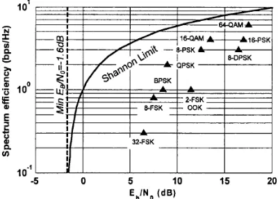
and bit error rate (BER). Under the same error rate and the same bandwidth efficiency, the smaller the minimum SNR needed is, the smaller the required transmission power will be, or in other words, under the same bit error rate and the same signal-to-noise ratio, the higher bandwidth efficiency is, which means that the same power can transmit more data, the smaller the unit power will be. Figure 1 shows the relationship between bandwidth efficiency and SNR in the absence of code modulation when the BER is 410
−in several common modulation schemes [14].
[image:2.612.318.518.550.693.2]It can be seen from the Figure 1 that under the same SNR, the closer modulation scheme is to the Shannon limit, the higher bandwidth efficiency will be, or with the same bandwidth efficiency, the better the SNR will be. Therefore we need to choose a low-power modulation. The Figure 1 also shows that, QPBSK (O-QPSK has the same bandwidth efficiency performance with QPSK) has a better bandwidth efficiency performance than BPSK. The amplitude modulation of ASK needs a larger carrier power than that of phase modulation and frequency modulation, has a weaker anti-noise capability, and is more subject to channel fading. Therefore, it is not an ideal low-power modulation scheme.
The IEEE 802.15.4 mainly uses DSSS encoding, which has low signal power and strong anti-jamming capability. An important indicator of the spread spectrum system is the degree of protection that it can provide to the communication signal under the limited power and the interference of external environment. This performance is rated by
the processing gain
G
y , the Equation 1 is asfollows:
R
R
R
W
T
W
T
W
D
N
G
gh ss chp
=
≈
=
=
min
2
2
(1)
SS
W
represents spectrum bandwidth,W
min is the minimum bandwidth required to transfer data.SS
W
approximately equals to the chip rateR
ch.min
W
approximately equals to the data rateR
0. It can be inferred that in DSSS encoding, when the data transmission rate remains the same, the higher the chip rate is, the greater the processing gain will be.In terms of transmission loss, the main difference of the four modulation schemes lies in the
frequency. According to the
equation
2 2
d
A
A
P
P
t et err
λ
,P
r represents the received power,λ
represents the carrier wavelength, and the other three parameters are the distance, and effective area of the transmitting and receiving antenna, which are of no relation to frequency. It can be seen that the receive power is inversely proportional to the carrier, that is, the received power is proportional to frequency. Therefore, 2450MHZ has a smaller transmission loss.In conclusion, 2450MHZ DSSS with physical layer modulated by O-QPSK is better than others in the design of low-power transceivers.
4. DESIGN OF 2450MHZ PHYSICAL
LAYER BASEBAND SPREAD
SPECTRUM
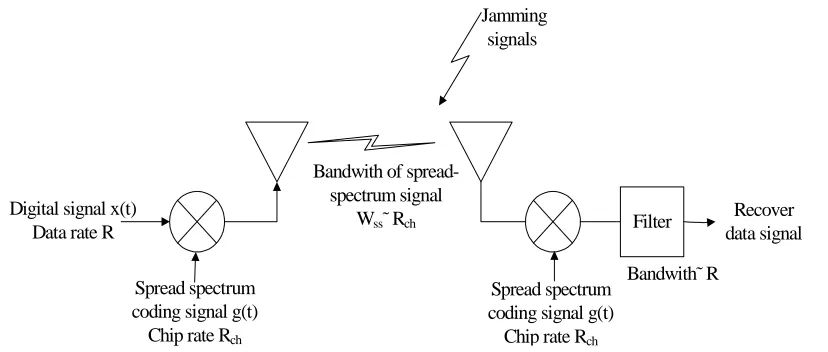
The structure of the DSSS is shown in Figure 2 .
Filter Digital signal x(t)
Data rate R
Spread spectrum coding signal g(t)
Chip rate Rch
Spread spectrum coding signal g(t)
Chip rate Rch
Recover data signal Jamming
signals
Bandwith of spread-spectrum signal
Wss˜ Rch
[image:3.612.99.513.478.654.2]Bandwith˜ R
Figure 2: DSSS Structure Diagram
According to the Equation
)
(
*
)
(
)
(
)
(
t
g
t
X
ω
G
ω
x
↔
We can see that spread spectrum system will realize spectrum spreading by multiplying the digital
signal
x
(
t
)
and the spreading spectrum coded signalg
(
t
)
, and dispreading by multiplying the signal received at the receive end and the replica of)
(
t
The IEEE 802.15.4 predetermines the encoding rule of the spreading code chip. The encoding rules
[image:4.612.129.481.90.346.2]of 2450MHZ physical layer chip is shown in Table 2.
Table 2: Symbol And Chip Mapping Data symbol
(binary)(b0b1b2b3)
Chip values (c0c1…………c30c31)
0000 11011001110000110101001000101110
1000 11101101100111000011010100100010
0100 00101110110110011100001101010010
1100 00100010111011011001110000110101
0010 01010010001011101101100111000011
1010 00110101001000101110110110011100
0110 11000011010100100010111011011001
1110 10011100001101010010001011101101
0001 10001100100101100000011101111011
1001 10111000110010010110000001110111
0101 01111011100011001001011000000111
1101 01110111101110001100100101100000
0011 00000111011110111000110010010110
1011 01100000011101111011100011001001
0111 10010110000001110111101110001100
1111 11001001011000000111011110111000
It can be seen from the chip structure that, there is a corresponding relationship between the chip of the first 8 symbols and that of the later 8 symbols. I channel of the first eight symbols is the same with the later 8 symbols respectively, while Q channel of them are in reverse order.
0
1
7
Comparer
i
Loader
i+8
Comparer
Q
I
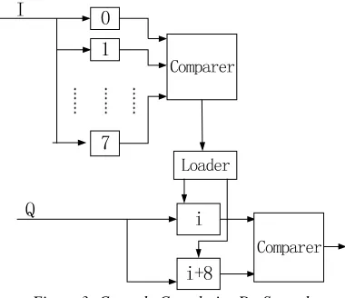
Figure 3: Cascade Correlative De-Spreader
The system demodulation and de-spreading are usually done through correlative calculation, which is of low BER. The de-spreading of 16 symbols by traditional correlative calculation requires the use of 16-channel parallel correlative calculation. Based on the above chip sequence analysis of the 16 symbols, this paper proposes a structure of cascade correlative de-spreader, i.e. first calculate with the I-channel of the signal and the I-channel of the first eight symbols, select i-th symbol according to the
maximum value, and then perform correlative calculation with the Q-channel and the Q-channel of the i-th and i+8 symbol. Reduce the number of correlation calculation to reduce circuit complexity and circuit consumption as shown in Figure 3.
5. 2450MHZ O-QPSK MODULATION AND DEMODULATION DESIGN
QPSK has a variety of modulation methods. According to the IEEE 802.15.4 specifications, we adopt two half-wave sine modulating waveform, I and Q. Therefore, it is very convenient to implement by using orthogonal multiplying circuit.
According to the Equation 2,
(
c k)
QPSK
t
A
t
S
(
)
=
sin
ω
+
ϕ
(2) we can get the QPSK orthogonal modulation Equation 3:t t
Q t t
I
t A
t A
t SQPSK
c c
c k c
k
ω ω
ω ϕ ω
ϕ
sin ) ( cos
) (
sin sin sin
cos ) (
− =
−
= (3)
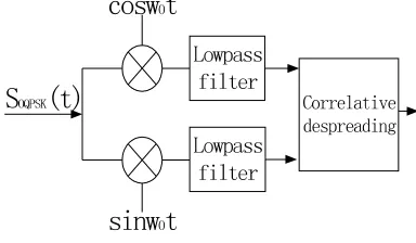
In demodulation, after
S
QPSK(t
)
multiplies with the in phase and quadrate carrier respectively, the I-channel signal and Q I-channel signal of the filtering can be restored. [image:4.612.97.287.440.604.2]modulation and demodulation frame can be shown in Figure 4 and Figure 5.
Shaping
pulse
Shaping
pulse
T
S/2
delay
I
Q
cosw
0t
[image:5.612.95.295.131.261.2]sinw0t
Figure 4: Modulator Structure Diagram
S
OQPSK(t)
Correlativedespreading
cosw
0t
sinw
0t
Lowpass filter Lowpass filter
Figure 5: Demodulator Structure Diagram
6. CONCLUSION
This paper studies the design of the ZigBee sensor unit according to the IEEE802.15.4 specifications, and analyzes the power consumption characteristics of the four physical layers under communication theories. We also put forward a cascade de-spreading method to reduce the power consumption based on the analysis of each physical layer, and finally propose the modulation and demodulation method combining IEEE 802.15.4 specifications with de-spreading method. In terms of the practical application of this method, the proposed node design is not only of low-power consumption but also of good communication performance.
ACKNOWLEDGEMENTS
The authors would like to thank the Key Item in the Guangdong Province Science & Technology Special Program of China (No. 2009A080202006), the Natural Science Foundation of Guangdong Province, China (No. 9151009001000021, S2011010001155), the Ministry of Education of
Guangdong Province Special Fund Funded Projects through the Cooperative of China (No. 2009B090300341), the National Natural Science Foundation of China (No. 61262013), and the High-level Talent Project for Universities, Guangdong Province, China (No. 431, YueCaiJiao 2011) for their support in this research.
REFERENCES:
[1] M. Chen, A. V. Vasilakos, and D. Grace, "Advances in Green Mobile Networks," Mobile Networks and Applications, pp. 1-3, 2012. [2] J. Wan, D. Li, Y. Tu, et al., "Performance
analysis model for real-time Ethernet-based computer numerical control system," Journal of Central South University of Technology (English Edition), vol. 18, pp. 1545-1553, October 2011.
[3] J. Wan, H. Yan, H. Suo, et al., "Advances in Cyber-Physical Systems Research," KSII Transactions on Internet and Information Systems, vol. 5, pp. 1891-1908, 2011.
[4] H. Suo, J. Wan, L. Huang, et al., "Issues and Challenges of Wireless Sensor Networks Localization in Emerging Applications," in Proc. of 2012 Int. Conf. on Computer Science and Electronics Engineering, pp. 447-451, 2012.
[5] M. Chen, J. Wan, and F. Li, "Machine-to-Machine Communications: architectures, standards, and applications," KSII Transactions on Internet and Information Systems, vol. 6, pp. 480-497, 2012.
[6] M. Chen, V. Leung, S. Mao, et al., "Receiver‐ oriented load‐balancing and reliable routing in wireless sensor networks," Wireless Communications and Mobile Computing, vol. 9, pp. 405-416, 2009.
[7] IEEE Standard for Information Technology. Part 802.15.4: Wireless medium access control (MAC) and physical layer (PHY) specifications for low-rate wireless personal area networks 2006.
[8] B. W. A. Cook, "Low Energy RF Transceiver Design," ed: EECS Department, University of California, 2007.
[image:5.612.97.289.313.425.2][10] B. Sklar, Digital Communications: Fundamentals and Applications, 2 ed.: Prentice Hall, 2001.
[11] M. Tubaishat and S. Madria, "Sensor networks: an overview," Potentials, IEEE, vol. 22, pp. 20-23, 2003.
[12] C. Desset and A. Fort, "Selection of channel coding for low-power wireless systems," in Vehicular Technology Conference, 2003. VTC 2003-Spring. The 57th IEEE Semiannual, pp. 1920-1924 vol.3, 2003.
[13] M. Chen, V. Leung, S. Mao, et al., "Energy-efficient itinerary planning for mobile agents in wireless sensor networks," pp. 1-5, 2009. [14] P. Gao, "Transceiver Chip Design for Wireless