Implementing a Standard Gradient Descent
Algorithm on FPGA Embedded Processor for
Two-Dimensional Field Sensor Calibration
Herman I. Veriñaz, Edgar M. Vela, Member, IAENG, Ronald A. Ponguillo, Member, IAENG
Abstract— To measure a vector field it is needed to use a field
sensor. This type of sensors measures both the direction and magnitude of a vector, e.g., magnetometers and accelerometers. These devices divide the physical space in two or three dimensions so that the sensor detects the components of the field in two or three axes respectively.
Usually, before using the data acquired from this sort of sensors, it is necessary to do a previous mathematical processing to guarantee that the measured field is truly proportional to the actual vector field. This is called calibration.
This work was developed for the self-calibration of a two-dimensional magnetometer used in a Robotracer for robotics competitions. However, the calibration can be done for any two-dimensional field sensor. For the proposed process, the sensor must be surrounded by a constant field because the calibration algorithm adjusts the sensor data using the fact that the magnitude of the field is constant.
The algorithm uses a linear model for the calibration of the sensor data. Then, to find the optimal values for the calibration constants, a Standard Gradient Descent algorithm was implemented.
The results of the implementation for different devices are presented in this work. It is showed the results for three accelerometers, MPU-6050, ADXL345 and FALCON-GX digital IMU. Time of execution is analyzed for each device using the soft-core processor NIOS II. The processor was running at 100 MHz of clock with 50% duty cycle. It is inside the FPGA EP4CE22F17C6N, Altera´s Cyclone IV family. All this work was done using the DE0-Nano development board.
Index Terms—Angle Estimation, Dual Extended Kalman
Filter, Sensor Fusion, Kalman Filter, Tilt Estimation.
I. INTRODUCTION
field sensor is a sensor that measures both the direction and magnitude of a vector field. For example, a magnetometer can detect the magnitude and
Manuscript received June 29, 2017; revised July 16, 2017.
H. I. Veriñaz is with the Escuela Superior Politécnica del Litoral, ESPOL, Faculty of Natural Science and Mathematics, Campus Gustavo Galindo, Km 30.5 Via Perimetral, P.O. Box 09-01-5863, Guayaquil, Ecuador (e-mail: [email protected]).
E. M. Vela is Electronics and Telecommunications Engineer, graduated at Escuela Superior Politécnica del Litoral, ESPOL, Faculty of Electrical and Computer Engineering, Campus Gustavo Galindo, Km 30.5 Via Perimetral, P.O. Box 09-01-5863, Guayaquil, Ecuador (e-mail: [email protected]).
R. A. Ponguillo is the Coordinator of the Basic Electronics Area and Researcher of the Vision and Robotics Center at the Escuela Superior Politécnica del Litoral, ESPOL, Faculty of Electrical and Computer Engineering, Campus Gustavo Galindo, Km 30.5 Via Perimetral, P.O. Box
direction of a magnetic field. Similarly, an accelerometer can sense the gravitational field.
This type of sensors is very useful in applications where there is a constant field surrounding the sensor board, because the constant direction of this field can be used as a reference to measure the angle of orientation of the sensor board. For example, an accelerometer can be used to measure the tilt, and a magnetometer can be used as a compass.
Usually, before using these sensors, it is needed to implement a routine to ensure consistency between the detected values in each axis. This means that, before using the data acquired from the sensor, it is necessary to do a previous mathematical processing to guarantee that the measured field is proportional to the actual vector field.
In many type of situations, this pre-processing or calibration algorithm must be part of the firmware of the device or equipment. This usually happens in robotics applications. For instance, in intelligent robot contests as Micromouse or Robotracer competitions [8], robots need to have an Inertial Measurement Unit (IMU) to control their position and orientation. The contestants prefer to calibrate the magnetometer sensor in the competition circuit because the magnetic field can change according to many circumstances, and there is not enough time to take data and execute an algorithm in a computer.
This work was developed to calibrate a magnetometer of a robot for Robotracer competitions. Nevertheless, the implementation can be used for the self-calibration of any two-dimensional field sensor. The only requirement is that there must be a constant field surrounding the sensor when the sensor is being calibrated. In fact, in the fourth section “Implementation and Results” it is showed how the algorithm is used to calibrate a two axes accelerometer.
The implementation is done on a NIOS II [1] single core processor running at 100 MHz, inside the FPGA EP4CE22F17C6N, using the DE0-Nano development board [2]. The calibration algorithm adjusts the sensor data using, as a main assumption, the fact that the magnitude of the vector field must be a constant. Then, it is assumed a linear model for the calibration of the sensor data. Finally, a Standard Gradient Descent algorithm was used to find the optimal values for the calibration constants. This is specified in the next section.
II. MATHEMATICAL MODEL
For the calibration, a linear model is going to be assume for each axis, this is represented as:
: i-th sensor reading for the x-axis. : i-th sensor reading for the y-axis.
: i-th calibrated reading for the x-axis. : i-th calibrated reading for the y-axis.
Constants that define the linear model.
In this model, and can take any real value, this means that the sensor reading can be translated by any value. But and can take any value except zero, because multiplying a sensor reading by zero makes no sense.
Now, the main assumption of the model is that the measured field is constant. Thus, its magnitude is also a constant:
(1)
Ideally, equation (1) holds for any . That is, given some and column vectors filled with “m” sensor data points, the aim is to find the and that best fit the model (1) for those points. First, the problem is simplified removing one unknown:
(2) (3)
Notice that equation (2) is valid because the value of the constant is different from zero. Thus, the model used is:
Constants that define the linear model.
To find these a, b and d values, the equation (3) is expressed in a linear form:
(4) Where:
With the equation (4), now it is can write a matrix linear model to implement the regression.
(5)
: Vector containing the sensor data of the y axis. : Vector containing the squares of each component of the vector x2.
: Vector containing the sensor data of the x axis. : Vector containing the squares of each component of the vector y.
: Vector full of ones.
: Vector containing the optimal constants to be found with the gradient descent algorithm.
Notice, that this is a linear regression problem and it has a well-known solution:
(6)
In this work, the matrix equation (6) will not be used. Instead, the optimal vector will be found using a standard gradient descent algorithm.
After the vector is found, the a, b, d and r constants are calculated using the following expressions derived from (4):
With these constants and with the equations (2) (3), the sensor can be calibrated.
III. GRADIENT DESCENT
To find the optimal vector a standard gradient descent algorithm is used [3]. The following recursive equations allows to calculate each of the four components of the gradient of the cost function:
Where m is the number of samples is the i-th component of the vector in (5), and the value
corresponds to the expression:
: the i-th component of the vector.
(7)
(8)
(9)
(10)
Finally, each component of the vector is calculated recursively as: (11)
The constant is known as the learning rate and was set by trial and error until reaching the least time of convergence. In this work, the vector is initialized with a vector filled with zeros. Before implementing the gradient descent algorithm, all features are scaled. It is necessary to do this scaling or normalization of the inputs for the algorithm to work properly. The following scaling factors were defined: (12)
(13)
(14)
(15)
With these factors defined, each input can be normalized in the following manner: (16)
(17) (18)
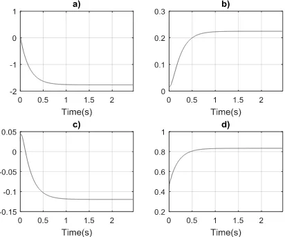
[image:3.595.314.528.336.510.2](19) Where and are the outputs of the sensor read directly. Then, when the gradient descent algorithm is executed, the scaled vector , output of the algorithm, is related with the not scaled vector with the equation: (20) Equations from (7) to (20) where implemented in the embedded processor NIOS II. IV. IMPLEMENTATION AND RESULTS The Gradient Descent algorithm was implemented in a NIOS II [1][8] single core processor running at 100 MHz clock frequency, inside the FPGA EP4CE22F17C6N, Altera´s Cyclone IV family, using DE0-Nano development board [2]. Four different sensors were tested: MPU-6050[4], ADXL345 [5] (included on DE0-Nano board), FALCON-GX digital IMU [6] and LSM303DLHC [7]. The ADXL345, MPU-6050 and LSM303DLHC were sampled each 30 ms and interfaced via I2C protocol. The FALCON-GX uses RS-232 serial protocol and data was sampled each 50 ms. All sensors are accelerometers except the LSM303DLHC. This last one sensor works as both, accelerometer and magnetometer. All accelerometers were rotated around an axis parallel to the earth surface, and the magnetometer was rotated around an axis normal to the earth surface. As mentioned in (11), vector is obtained recursively. Algorithm run until reaching the minimum error condition: (21) Evolution of can be seen from Figure 1 to Figure 5, each corresponds to a calibrated sensor.
Fig. 1. Optimal constants for Falcon-GX accelerometer. a) Theta’s first component. b) Theta’s second component. c) Theta’s third
component. d) Theta’s fourth component.
Fig. 2. Optimal constants for ADXL345 accelerometer. a) Theta’s first component. b) Theta’s second component. c) Theta’s third
[image:3.595.322.528.560.731.2]Fig. 3. Optimal constants for MPU-6050 accelerometer. a)Theta’s first component. b) Theta’s second component. c) Theta’s third
[image:4.595.312.535.107.276.2]component. d) Theta’s fourth component.
Fig. 4. Optimal constants for LSM303DLHC accelerometer. a)Theta’s first component. b) Theta’s second component. c) Theta’s third
component. d) Theta’s fourth component.
Fig. 5. Optimal constants for LSM303DLHC magnetometer. a)Theta’s first component. b) Theta’s second component. c) Theta’s third
component. d) Theta’s fourth component.
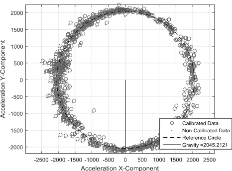
From vector, can be calculated. So, equation (11) could be drawn to demonstrate how algorithm works. These results are shown from Figure 6 to Figure 10.
[image:4.595.64.271.279.449.2]The magnitude of the field measured is also given on the same figures. These measures varies between accelerometers because each one are scaled on its own units determined by manufacturer.
Fig. 6. Calibration results for FALCON GX accelerometer.
Fig. 7. Calibration results for ADXL345 accelerometer.
[image:4.595.317.531.321.490.2] [image:4.595.65.272.500.672.2] [image:4.595.311.544.532.704.2]Fig. 9. . Calibration results for LSM303DLHC accelerometer
Fig. 10. Calibration results for LSM303DLHC magnetometer
It can be noticed that not all sensors converge with similar behavior. As seen on Table 1, the speed of convergence of the algorithm depends on the sensor. This give idea on how decalibrated the sensor is working, i.e., for the bigger time of convergence, the corresponding sensor is more decalibrated.
TABLE 1
ALGORITHM PERFORMANCEFOR DIFFERENT SENSORS
Type of Sensor Device Iterations Time
Accelerometer
Falcon-GX 26905 89.85 s
ADXL345 738 2.46 s
MPU-6050 382 1.27 s
LSM303DLHC 371 1.23 s
Magnetometer LSM303DLHC 242 0.80 s
In Figure 7, it is highly visible how the Falcon-GX is working far from its reference, so Gradient Descent Algorithm takes longer to converge. Otherwise occurs with LSM303DLHC accelerometer.
Although LSM303DLHC magnetometer is decalibrated, as shown on Figure 10, it has a shorter convergence time. This is because magnetometer reading is not affected by the movement of the sensor during the experiment, so there are no scattered data points. As accelerometer reads literally
how sensor moves, it is affected if sensor is not on a uniform circular movement.
Despite all circumstances that cause errors in the reading of the sensors, the algorithm runs relatively fast when is applied on an embedded platform.
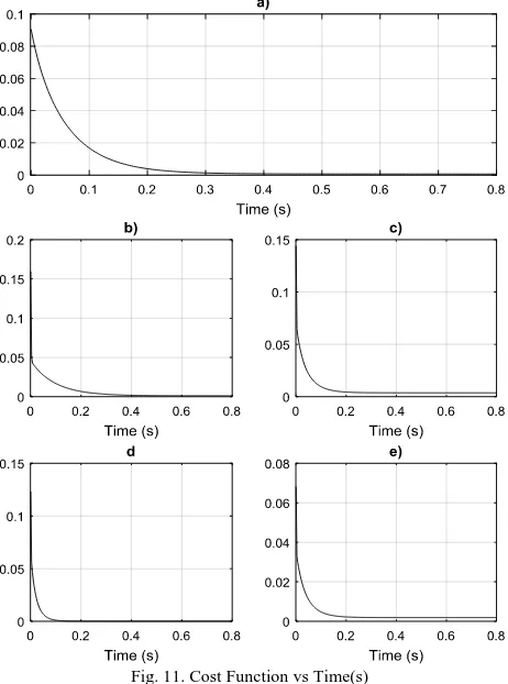
Another fact to be considered is that the cost function is always decreasing for every tested sensor, although some of the constants do not appear to be converging. The learning rate from equation (11), was finally set at 0.73. The cost function behavior can be seen in Figure 11. Notice that is only displayed 0.8 seconds of the runtime. If it is wanted the algorithm to be faster, the error condition could be set higher than 0.0000001 (21).
Fig. 11. Cost Function vs Time(s)
a)FALCON GX accelerometer. b) ADXL345 accelerometer. c) MPU-6050 accelerometer. d) LSM303DLHC accelerometer.
e) LSM303DLHC magnetometer.
V. CONCLUSION
This paper presented an interesting method for auto calibration of sensors based on vectorial field that can be used in robotics applications. The method showed includes a standard gradient descent algorithm used in some machine learning applications. The results validate the method and the embedded system used warranties the usability in robotics applications.
[image:5.595.62.272.264.426.2] [image:5.595.47.294.555.651.2]REFERENCES
[1] Chu, P. P., "Embedded SOPC Design with NIOS II Processor and VHDL Examples", Hoboken, NJ: John Wiley & Sons, Inc., 2011. [2] Terasic Technologies Inc., DE0-Nano User Manual, 2013.
[3] James, G., Witten, D., Hastie, T., & Tibshirani, R. (2013). An introduction to statistical learning: with applications in R (Vol. 103). Springer Science & Business Media.
[4] InvenSense, "MPU-6000 and MPU-6050 Product Specification Revision 3.4", MPU600 Datasheet, Nov. 2010 [Revised Aug. 2013] [5] Analog Devices, Inc., “3-Axis, ±2 g/±4 g/±8 g/±16 g Digital
Accelerometer ADXL345”, ADXL345 Datasheet Rev. E, 2015 [Revised Jun. 2017]
[6] O-NAVY LLC, “ONI-23505 OEM Digital IMU Module”FALCON-GX digital IMU Datasheet Rev. A, 2003
[7] STMicroelectronics, “Ultra-compact high-performance eCompass module: 3D accelerometer and 3D magnetometer”, LSM303DLHC Datasheet Rev. 2, Nov. 2003