Numerical Modeling and Evaluation of Involute
Curve Length of a Spur Gear Tooth to Maintain
Constant Velocity Ratio While in Motion
1
Enesi Y.Salawu, 1Imhade P. Okokpujie, 1*Oluseyi O. Ajayi, Sunday A.1Afolalu, 2M.C.Agarana
Abstract - Numerical modeling and values of the involutes curve length for a spur gear has been carried out using polar coordinate principles and application of calculus theorems. A set of values for base radius of the gear were considered from 10mm, 20mm, 30mm, 40mm and 50mm. The study also considered a pressure angle of 10°, 20°, 30°, 40°, and 50° for this set of values. The result of the length of involutes curve obtained at a pressure angle of 10° showed a significant increase in the length of the curve generated as the base radius increases that is at10° and for the set of the base radius values, the length obtained are:0.1555mm,0.311mm,0.4665mm,0.622mm and 0.7775mm. The result also revealed that at higher pressure angle of 50°, a better length of the curve was equally generated as seen from the plot.That is at 50° and with the base radius of 10mm, 20mm, 30mm, 40mm, and 50mm, the corresponding length of involutes are 7.1014mm, 14.203mm, 21.3045mm, 28.406mm and 35.5075mm. This equally validate the direct proportionality of length of curve as the square of tan a from equation.
Index Terms: Numerical Modeling, Involutes curve, spur gear, constant velocity and motion
NOMENCLATURE: a=Pressure angle in degrees
Base radius in (mm)
= Angle at which the involutes curve at Point P B= Radius of curvature of the involutes (mm) L= Length of the involutes curve (mm) x= Distance between centre O and point P (mm)
X1,Y1= Length of involutes curves from standard equations
= Is the angle subtended at the centre by the radius and the reference axis from where the involutes is generated (Y-axis)
1. Department of Mechanical Engineering, Covenant University, P.M.B 1023, Ota, Ogun State, Nigeria
2. Lecturer in the department of Mathematics, Covenant University, Nigeria and presently a Post-Doctoral Fellow in the department of Mechanical Engineering Science, University of Johannesburg, South Africa.
Corresponding Author: [email protected]
I. INTRODUCTION
To fulfill the fundamental law of gearing, that is to keep up a steady speed proportion in a couple of between lattice gears, the tooth bends are to so composed that the basic ordinary to the tooth profiles at the purpose of contact will dependably go through the pitch point. The bends fulfilling such condition are named as conjugate bends or curves.
The involute of circle is characterized as the bend which is produced by the end purpose of a rope which is kept tight while being loosened up from circle. Some other point on the rope will likewise produce a comparative involute bend as the rope is dynamically unwrapped from the circle.
Suresh et al [1] developed an involute spur gear template by using parametric technique and computer aided design. This method provides accurate involute curve creation using the formulas and the geometric equations. Make the involute bend profile. The work likewise revealed that, the involute bend by condition method permits utilizing either Cartesian as far as X, Y, and Z or tube shaped facilitate frameworks to make the involute bend profile. Since gear geometry is controlled by a couple of essential parameters, a nonspecific apparatus can be planned by three regular parameters to be specific the weight edge (a), the module (m), and the quantity of teeth (z). The greater part of the present day CAD frameworks has no worked in instrument for planning such riggings. The paper work was an endeavor in using the idea of parametric innovation to build up a layout outfit. The rigging so created has genuine involute profile, which is a sensible plan. This will enable rolling out improvements to the apparatus configuration by utilizing parametric input. Pinaknath [2] did a work on design analysis of spur gear. The work examines the bending stress behavior of an involute spur gear tooth under static loading conditions.
relocation qualities of tooth under powerful loading conditions. Jaganath et al [3] did the evaluation of the wear behavior of a nonmetallic gear. The composite gear material was evaluated to check for the friction and wear resistance in adhesive and abrasive modes. Direct measurement of weight loss due to wear was carried out and it was observed that adhesive wear rate reduces drastically when the cement loading increases. The shear strength and surface energy of the composite material changed as a result of the improvement on the toughness and hardness of the material. Ahlroos et al [4] investigated the micro pitting performance of gear to know the effect of surface roughness using twin disc. The work examined lubricant type and surface treatment on micro pitting performance of twin case hardened steels. The result of the experiment revealed that the surface roughness of the gear had a major impact on the micro pitting performance. Enesi etal. [5] carried out a theoretical modeling work on stress distribution on a spur gear via finite element approach. The study compared constant, linear and non-linear temperature distribution on the tooth surfaces. The outcome of the study showed that the maximum effective stress occurred at the tip of the gear tooth and decreased circumferentially deep into the gear material. The study also revealed that a nonlinear distribution of the temperature around the gear tooth made the gear to undergo stress and also the tendency of fatigue failure.
Sheng et al[6] also carried out a study on the micro-pitting fatigue life of lubricated contact to investigate the parameters on micro-pitting performance of lubricated point contacts of rough surfaces. The test was conducted using a test matrix that spans the operating distances of the sun-planet gear pair of a wind turbine gear box which was equally constructed using the Fractional Factorial techniques to rank the influences of contact pressure. The result showed that a run-in stage with higher contact pressure and lower rolling velocity reduce the effects of micro-pits. Also for the operating stage follows, lower roughness amplitude, lower slide-to-roll ratio, higher rolling velocity and lower contact pressures were observed to have reduce the effects of micro-pit.Safraz et al[7] carried out contact stress analysis for a gear pair in a lathe machine under static loading conditions using Hertz theory and finite element method. The result of the analysis highlighted the influence of different modules on the contact stresses after comparing the two methods.According to Maitra [8] to satisfy the conditions of conjugate action and the law of gearing, the tooth geometry must be made of curves designed to meet the requirements of meshing.More so for a constant velocity ratio, the pitch point must remain stationary at a fixed point
The aim of this work is to develop a numerical model and use the developed model to compute numerical values of the length of involutes curve that will enhance constant velocity ratio of a pair of inter-meshing gear which will eventually reduce the backlash problems in spur gear design.
II. METHODOLOGY
In this study, the involutes spur gear was represented by a
end point of a cord that is kept stiff while being unwound from the circle as shown in the figure below and the model was developed using the mathematical principles in polar coordinate system.
Fig.1: Involutes Curve Generation using polar coordinate system
From the figure 1,
Recall that from calculus)
Applying the polar coordinate system from calculus
)
Where;
is the angle subtended at the centre by the radius and the reference axis from where the involute is generated (Y-axis) from equation ( 1),
From equation (2),
By integrating and solving the equation (5)
To model the length of the involute curve of the gear tooth we apply the parametric equations of the involute curve.
Also using the general formula for finding the length of a curve, we have length L, of the involute from Y to point P as:
Or =
Hence
=
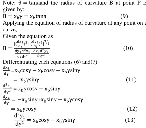
Note: and the radius of curvature B at point P is given by:
Applying the equation of radius of curvature at any point on a curve,
Given the equation as
(10)
Differentiating each equations (6) and(7)
=
=
+
Substituting equations (11), (12) and(13) into equation (10) we have,
Where,
B= radius of curvature
Base radius which depend on the size of the gear and
Pressure angle
III. RESULTS AND DISCUSSION
Fig.2 is the plot of the base radius of the gear versus the values of involute curve length which were obtained from the empirical model for the length of the involute curve as shown
in Table I. The base radius was varied from
10mm,20mm,30mm 40mm and 50mm respectively and the pressure angle was taken to be 10°. It can be seen from the result that for each of the base radius given for a constant pressure angle, there was also an incremental change in the corresponding values of the length of the involute curve generated. This value ranges from 0.1555mm, 0.311mm, 0.4665mm, 0.622mm and 0.7775mm. This implies that the higher the base radius, the more the length of the involute curve is generated.
Numerical Calculations Using
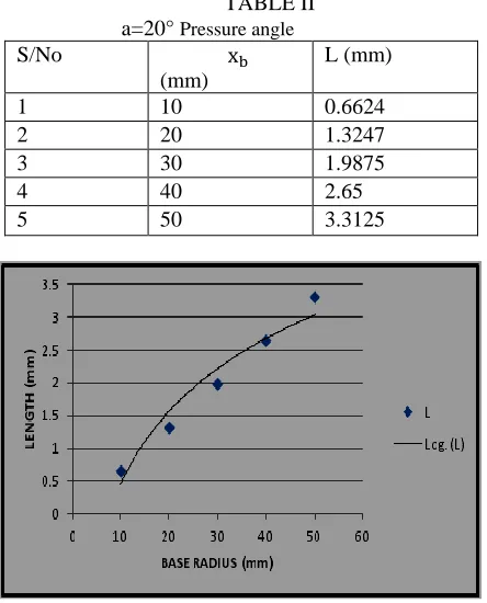
Table II and Fig. 3 present the result of numerical analysis and the plot of base radius of the gear against the length for a constant pressure angle of 20° and base radius which ranges from 10mm to 50mm in step of 10mm. a rapid increase in the length of the involutes curve was also observed. This is as a result of increased pressure angle. The result also revealed that the higher the pressures angle of the gear the longer the involutes curve.
Similarly Table III showed the numerical values obtained using the model generated for length of the curve of the involutes while Fig. 4 depicts the plot of the numerical result for an increased pressure angle of 30° for the same base radius values ranging from 10mm to 50mm. the values of the involutes length were equally high at a pressure angle of 30° compared to when the pressure angle was of 20°. This also showed that and increase in the pressure angle will increase the involutes curve length.
More so Table IV and Fig. 5 present the numerical values and graphical result of the length of involutes curve for the same values of base radius, but at a pressure angle of 40°. A geometric increase in the length of the involutes was equally felt, for instance at a base radius of 50mm, the corresponding length of the involutes was 17.6025mm.
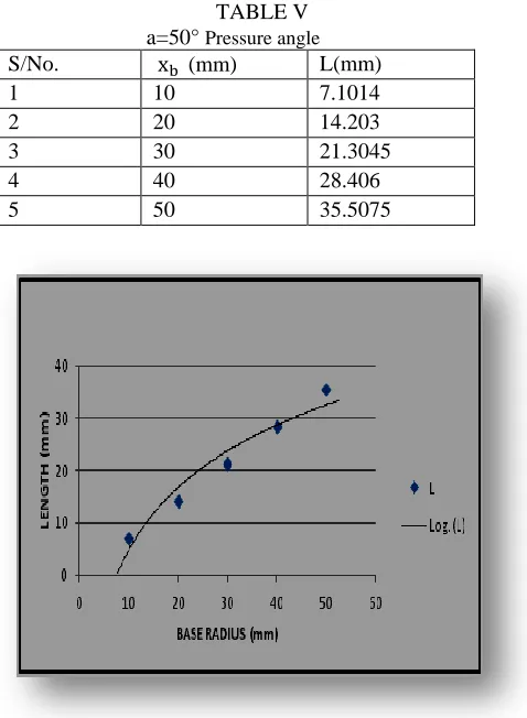
Table V and Fig. 6 also present the numerical result from the model and the graphical interpretation of the result at a pressure angle of 50°. However the length of the involutes obtained were longer at this pressure angle at the varied values of base radius of the gear. The involutes obtained are
7.1014mm, 14.203mm, 21.3045mm, 28.406mm and
35.5075mm. Therefore it can be concluded that, the higher the pressure angle, the more the involutes curve that would be obtained.
IV. CONCLUSION
This paper aimed at developing a model that can be used to obtain numerical values for generating the spur gear involutes curve. This will equally improve the spur gear design and maintenance of velocity ratio in a pair of inter-meshing spur gears. The model has been developed and numerical value has been calculated and the result was also interpreted using the excel graphs.
It can be concluded that the higher the pressure angle of the gear tooth, the more involutes that will be generated. Therefore the gear tooth characterized with well designed involute properties is expected to perform and maintain a constant velocity ratio when in operation
ACKNOWLEDGMENT
[image:3.612.42.295.52.273.2]TABLE I a= 10° Pressure angle
S/No. (mm) L(mm)
1 10 0.1555
2 20 0.311
3 30 0.4665
4 40 0.622
[image:4.612.315.536.54.315.2]5 50 0.7775
Fig. 2: Plot of Length of Involutes versus Base radius of the Gear @ a=10o
TABLE II a=20° Pressure angle
S/No
(mm)
L (mm)
1 10 0.6624
2 20 1.3247
3 30 1.9875
4 40 2.65
5 50 3.3125
Fig.3: Plot of Length of Involutes versus Base radius of the Gear @ a = 20o
TABLE III a= 30° Pressure angle
S/No. (mm) L(mm)
1 10 1.6667
2 20 3.3333
3 30 4.9995
4 40 6.6666
5 50 8.3333
[image:4.612.316.541.366.648.2]Fig. 4:Plot of Length of Involutes versus Base radius of the Gear @ a =30o
TABLE IV a=40° Pressure angle
S/No. (mm) L(mm)
1 10 3.5205
2 20 7.041
3 30 10.5615
4 40 14.082
5 50 17.6025
[image:4.612.49.271.369.644.2]TABLE V a=50° Pressure angle
S/No. (mm) L(mm)
1 10 7.1014
2 20 14.203
3 30 21.3045
4 40 28.406
5 50 35.5075
Fig. 6: Plot of Length of Involutes versus Base radius of the Gear @ a=50o
REFERENCE
[1] Suresh Babu V., Aseffa Asmare Tsegaw“Involute Spur Gear Template Development byParametric Technique Using Computer Aided Design”International Multi- DisciplinaryJournal, Ethiopia Vol. 3 (2), January, 2009 (Pp. 415-429)
[2] Pinaknath Dewanji “Design and Analysis of spur Gear”International Journal of Mechanical Engineering and Technology (IJMET)Volume 7, Issue 5, September-October 2016, pp.209–220
[3] Jagannath Sardar, Dibakar Bandopadhya “Evaluation of wear behavior of a nonmetallic spur gear”5th International & 26th All India Manufacturing Technology, Design and Research Conference (AIMTDR 2014) December 12th–14th, 2014, IITGuwahati, Assam, India.
[4] T.Ahlroos, H.Ronkainen, A.Helle, R.Parikka, J.Virta,S.Varjus “Twin disc micropitting tests” Tribology International 42 (2009) 1460–1466.
[5] Salawu Enesi Yekini, Oluseyi.O Ajayi, O.O Olatunji“Theoretical Modelling Of Thermal-Hoop Stress Around The Tooth Of A Spur Gear In A Filler Machine” Journal of Multidisciplinary Engineering Science and Technology (JMEST) ISSN: 3159-0040 Vol. 2 Issue 7, July – 2015
[6] Sheng Li, Ahmet Kahraman “Micro-pitting fatigue lives of lubricated point contacts: Experiment and model validation”International Journal of Fatigue 48 (2013) 9–18 [7] Sarfraz Ali N. Quadri1, Dhananjay R. Dolas “Contact Stress
Analysis of Involute Spur gear under Static loading” International Journal of Scientific Research Engineering & Technology (IJSRET), ISSN2278 – 0882, Volume 4, Issue 5, May2015”