1
A Concept for Actuating and Controlling
a Leg of a Novel Walking Parallel
Kinematic Machine Tool
Adam Rushwortha, Dragos Axinte a*, Mark Rafflesa and Salvador
Cobos-Guzmana
a University of Nottingham, Machining and Condition Monitoring Research Group, University Park, Nottingham, NG7 2RD United Kingdom, Tel: +44 (0) 1159514117 (e-mail:
[email protected], [email protected],
[email protected], [email protected],).
Abstract
The scope of this paper is to present a novel method of actuating the legs of a walking parallel kinematic
machine tool (WalkingHex) such that the upper spherical joint can be actively driven while walking and
remain a free, passive joint while performing machining operations. Different concepts for the number of
Degrees of Freedom (DoF) and methods for actuating the chosen concept are presented, leading to a
description of a three-wire actuated spherical joint arrangement. The inverse kinematics for the actuation
mechanism is defined and a control methodology that accounts for the redundantly actuated nature of the
mechanism is explored. It is demonstrated that a prototype of the system is capable of achieving a motion
position accuracy within 5.64% RMS. Utilising the concept presented in this paper, it is possible to develop
a walking robot that is capable of manoeuvring into location and performing precision machining or
inspection operations.
Keywords:
2
1
Nomenclature
PKM Parallel Kinematics Machine
DoF Degree(s) of Freedom
CMM Co-ordinate Measuring Machine
FPGA Field Programmable Gate Array
RMS Root Mean Square
DC Direct current
𝜃 Angle of rotation of leg about x-axis, rad
𝜙 Angle of rotation of leg about y-axis, rad
𝑟𝑆 Offset radius of wire connections to platform with respect to centre of
spherical joint, m
𝑟𝐿 Offset radius of wire connections to leg with respect to axis of leg, m
𝑤𝑖 Length of wire 𝑖, m
𝑙 Distance between centre of upper spherical joint and top of wire attachment plate, m
𝑺 Matrix containing locations of upper wire attachment in Cartesian form, m
𝑳 Matrix containing locations of wire attachment points on the leg in Cartesian form, m
𝑾 Matrix containing the vectors corresponding to each wire position, m
R1 Internal resistance of DC motor, Ω
3
V1 Supply voltage, V
J Moment of inertia of rotor (including gearbox, spindle etc.), 𝑘𝑔𝑚2
k Electromotive constant, 𝑉𝑠 𝑟𝑎𝑑−1
b Damping ratio
𝐾𝑃 Proportional gain
𝐾𝐷 Derivative gain
N PD Filter coefficient
𝑎𝑖 length of actuator I, m
𝑑 perpendicular distance between upper spherical joint and actuator axis, m
𝐿𝑙𝑒𝑔 length of leg, m
𝑥𝑖 coordinate in the ith direction of foot, m
2
Introduction
2.1
Parallel Kinematics Machines
4 tasks [5-7]; this leads to the consideration of how a PKM should autonomously relocate in a target environment.
While wheeled and tracked robots may be faster and less complex in terms of both construction and control than legged robots [8], they lack the capacity to navigate freely in complex and uneven environments, rendering more than 50% of the Earth’s surface completely inaccessible to this category of mobile robot [9]. As such, the reason that legged mobile robots may be desirable is for their ability to traverse difficult terrain and navigate in tight spaces. This ability makes them suited to performing tasks that would be difficult or dangerous for human intervention (e.g. [10]) and ideal for industrial repair where human intervention should be avoided. As PKMs already exist in a format consisting of 6 legs e.g. the Stewart Platform [11], the concept of utilising these legs for walking is a natural transition.
2.2
Free-leg Hexapod
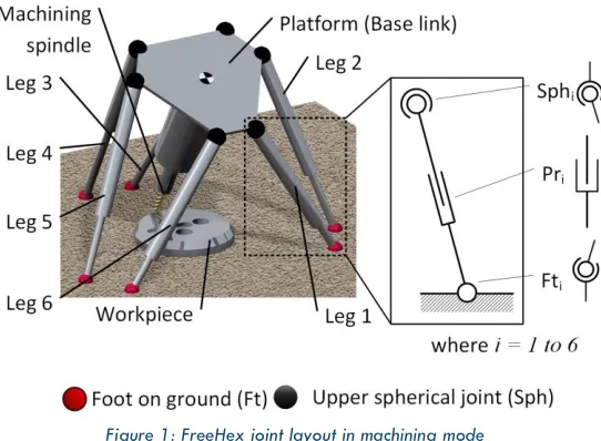
A Free-leg Hexapod (FreeHex) [12-14] with a PK structure and six independent,
individually placed feet has been reported. The legs are attached to the upper platform by passive spherical joints (Sph1-Sph6), mounted in pairs in a rotationally symmetrical
pattern while the length of the legs can be varied (to allow 6-axis movement of the upper platform for machining operations) using prismatic joints (Pr1-Pr6) as illustrated in Figure 1.
5
Figure 1: FreeHex joint layout in machining mode
Karimi and Nategh show that grouping the upper spherical joints and lower spherical joints in pairs as follows provides the best quality workspace for a hexapod PKM [15]: pairs of joints that are closer together at the top of the legs should not be close at the foot, but the foot should be paired with (and closer to) the foot of the leg whose upper joint was further away (but still consecutive); thus feet are paired Ft1 and Ft2, Ft3 and Ft4
etc. and upper spherical joints are paired Sph6 and Sph1, Sph2 and Sph3 etc. as per
Figure 1.
In its current state, the FreeHex is unable to perform any motion other than translating and orientating the platform; this is due to the fact that this motion consists of six degrees of freedom and there are only six actuators in the system, meaning that additional actuators must be included to allow additional motions. Statically stable walking motion is
characterised by lifting, translating and then lowering the feet and translating the robot base link. It is therefore necessary to modify the system such that it is capable of
6 must be able to operate in two modes: ‘walking mode’ and ‘machining mode’ and the system must allow for the current machining functionality to be retained, preferably in such a way that the kinematics and accuracy are unaffected while the machine is in ‘machining mode’.
2.3
Some considerations on the leg designs for walking parallel kinematic
configurations
An important aspect in the consideration of the design of mobile legged robots is the kinematic structure and construction of the legs; this determines how the robot walks and affects the design of the base link. Designing legs is a non-trivial process, particularly for quadrupeds or hexapods utilising a tripod gait, since half of the weight of the robot and payload (that could include a machining spindle and additional robotic manipulators) will be carried by one leg at different stages in the gait cycle. Existing robot legs belonging to statically stable walking robots can be broadly grouped into three categories, as suggested by Kar [16]: Straight Line Mechanism, Articulated and Gravitationally Decoupled.
7 The workspace for each leg of this type of robot is relatively small and the range of motions is very limited, making traversing obstacles very difficult and rendering this category of robot unsuitable for use in a PKM.
Articulated legs are those most closely resembling the legs of mammals (mammalian), reptiles (reptilian) and insects (insectoid). It is perhaps not surprising that much of the literature covers leg structures similar to those present in nature since these designs are well proven by the creatures bearing them. They rarely feature prismatic joints, since these are not present in the natural world, but have a hip containing two perpendicular revolute joints. Mammalian legs typically have a knee containing a revolute joint located part way down the leg that is typically kept below the hip during walking. The revolute joint is normally oriented with its axis perpendicular to the direction of travel; as such, mammalian walking robots walk best in only one direction and tend to have four legs.
Examples of this type of articulated robot include: the GE Walking Truck [20], a
mammalian quadruped capable of performing complex motions with the assistance of a skilled human controller, Bigdog [21], a very nimble load-bearing quadruped, and the OSU Hexapod [22, 23].
Insectoid type legs tend to have knee joints that are located above the hip joint, forming an inverted V-shape (see Figure 2), with the knee joint axis initially parallel to the
8 (a) (b)
Figure 2: Articulated legged walkers: GE Walking Truck [20] (a) and TUM Walking Machine [24] (b)
Due to the articulations present in this type of leg, there is a high degree of flexibility over where the feet can be placed, increasing the workspace for a leg, the ability to avoid obstacles and the maximum walking speed. These abilities come with the cost of additional actuators, more complex control systems and a higher energy usage, but do not limit the potential for usage in a PKM.
In an attempt to reduce energy costs for operation and utilise actuators more effectively, a third category of leg emerged: gravitationally decoupled legs. This design methodology separates the vertical motion associated with lifting legs and supporting the mass of the robot from the translatory motion used to advance the robot base-link; to put it simply, one set of actuators holds the robot up, while another set propel it forwards. This allows for gaits whereby the centre of mass of the system remains at a fairly constant height, reducing the lifting effort for any given gait cycle. Two of the most popular configurations for this type of leg are orthogonal and pantographic structures.
9 slow, is energy efficient. ROWER [10] uses a SCARA (Selective Compliance Articulated Robot Arm) leg configuration with two revolute jointed links connected to a prismatic joint. Pantographic structures use complex linkage arrangements based on the illustrator’s tool, the pantograph, to achieve the decoupling of horizontal and vertical actuation (such as Figure 3(b)). Odex [27] is a classic example of the use of this mechanism and represented a large step forward in the design and control of walking robots. However, the kinematics of these mechanisms is not entirely straightforward and the foot can only move along certain paths, meaning that this structure is more difficult to utilise in a PKM.
[image:9.612.106.519.302.457.2](a) (b)
Figure 3: Ambler Circulatory Walker [26] (a) and a generic 2-Dimensional pantographic mechanism (b)
An attempt has recently been made [28] to address the problem of a mobile in-situ repair system, but the SHeRo fails to display any evidence that its kinematic arrangement and structure is capable of producing the stiffness and precision motions required for high-speed machining operations, such as those performed by the FreeHex.
2.4
PKM Joints
The design of the ‘legs’ for six DoF PKMs, working as machine tools, is somewhat different to that of current walking hexapod legs and can largely be generalised by the type of joints used in the leg. The joints at either end of each leg must allow for at least two
Fti
Pri
Rev2i
Rev3i
Rev4i
Rev1i
Rev7i
Rev6i
Rev5i
Pantographic mechanism
Upper leg
10 degrees of passive rotation in order to allow the platform to be located with three
degrees of translation and three of orientation.
Designs based on the original Stewart Platform [11] utilise spherical (ball and socket) joints, providing three degrees of freedom per spherical joint with legs that simply expand and contract telescopically to allow the control of a single degree of freedom, such that the platform is accurately constrained in six degrees of freedom, but the legs are unconstrained in rotation about their own axis. These additional degrees of freedom do not affect the theoretical efficacy of the machine, but may introduce real world
complications due to twisting of electrical control cables.
Spherical joints offer simple inverse kinematics and a high level of accuracy due to
precision location of centre of rotation; however, very high precision, well-made ball joints are required in order to ensure this level of precision and these systems may experience hysteresis effects.
11 Flexure joints have also been used recently for some more unconventional PKM designs. These joints pose control and kinematic problems that are non-trivial and require complex models and control algorithms to utilise; this is due to the fact that the locations of the joint pivots depend on the current level of flexure. McInroy [32] reports on a control
methodology allowing for the use of these joints in a hexapod with an otherwise Stewart Platform structure, showing that a degree of accuracy can be achieved with difficulty. At present, spherical joints offer a good balance of accuracy and simple kinematics and are well proven in their use in hexapods such as the FreeHex; however, there are no walking robots that currently utilise spherical joints anywhere other than in the connections between the legs and feet.
2.5
Scope of paper
As is evident from the literature, there is no current joint configuration that meets the requirements both of a PKM and a walking robot, a hybrid configuration must be developed in order to allow the construction of a precision machine-tool walking robot. The scope of this paper is a study of the conceptual development of the design of a single leg of the WalkingHex that allows for operation of the robot as whole both for walking, with active, actuated spherical joints, and carrying out machining operations, with passive spherical joints. The overall joint arrangement is considered and a detailed actuation design is subsequently developed. The inverse kinematics required for operating the selected leg design are derived and verified. A prototype of the leg actuation mechanism is presented along with details of control methodology and experimental verification of functionality, including accuracy analysis.
12
2.6
Design Methodology
[image:12.612.211.405.145.679.2]The methodology used for the design process is based on the Generic Design Process Model (Figure 4):
Figure 4: WalkingHex Design Process Model (Based on ‘The Generic Design Process Model’ [34])
Design Requirements
Generate leg concepts
that allow for:
• Walking
• Multi-axis platform motion
Evaluate designs based on:
• Flexibility of foot placement
• Estimated walking speed
• Complexity
• Effect on machining accuracy
• Mass
Select design and model
𝑧 = 𝐿𝑙𝑒𝑔𝑐𝑜𝑠 𝜃 cos 𝜙 = 𝐿𝑙𝑒𝑔𝑐𝑜𝑠 asin 𝐿𝑦
𝑙𝑒𝑔
cos asin 𝐿𝑥
𝑙𝑒𝑔
x = 𝐿𝑙𝑒𝑔𝑠𝑖𝑛 𝜙 ⇔ 𝜙 = asin 𝐿𝑥
𝑙𝑒𝑔 y = 𝐿𝑙𝑒𝑔𝑠𝑖𝑛 𝜃 ⇔ 𝜃 = asin 𝐿𝑦𝑙𝑒𝑔
Generate actuation concepts
That allow for:
• Controllable rotation of spherical joint
• Disengagement Pr1i Sph1i Sph2i Pr5i Pr2i Pr4i Platform Magnets Prismatic Joint Spherical Joint Motor Leg Structural Part d Pr3i Pr1i Pr3i Pr2i Pr4i Rev1i Rev3i Rev4i Rev2i Magnets Revolute Joints Gimbal Joint Prismatic Joint Spherical Joint Motor Leg Structural Part Sphi Platform Sph4i Pr1i Sph2i Sph1i Sph3i Pr2i Sph5i Pr3i Prismatic Joint Spherical Joint Motor Leg Structural Part Platform Pr3i Pr1i Pr2i Sph1i Platform Ball cable attachment Prismatic Joint
Spherical Joint Motor Leg Structural Part Wire
Evaluate designs based on:
• Accuracy
• Size
• Strength
• Disengagement method
• Mass
Select design; model and prototype
13 This model can be broken down into several stages:
1. The needs of the end users are gathered and interpreted and a requirements definition is formulated. This is then presented to the end users and validated in an iterative process that is performed in conjunction with the determination of what is feasible.
2. Ideas for leg design are generated based on the requirements definition with a view to fulfilling all the requirements in an optimal way.
3. Ideas are evaluated qualitatively and quantitatively and some consideration is made of possible gaits where relevant
4. One or more concepts are chosen for further development and may be fed iteratively through the cycle until fit for further development
5. Concepts for methods of actuating the selected leg design(s) are generated 6. Each idea is evaluated through the use of mathematical and computerised models,
CAD simulations and prototypes.
7. One or more designs are chosen to be developed and are fed iteratively through the cycle until a suitable level of optimisation is reached and one final design is selected
8. The final design is produced and manufactured.
3
Conceptual designs for overall leg joint layout
3.1
Leg Design Requirements
Since the WalkingHex must be capable of both walking and machining, it is important to consider the overall joint layout for a leg. The WalkingHex will be equipped with six identical legs, with spherical joints at each end providing the accurate joint location
14 When considering the choice of designs for the leg, it is instructive to consider which
factors are important to the overall system:
Flexibility of foot placement – it is beneficial if the feet can be placed freely within the environment without having their placement constrained by the shape of the leg; this also increases the leg’s working volume. An optimal solution might permit the leg to change orientation in order to avoid obstacles.
Estimated walking speed – due to the nature of the work that may be carried out by such a robot, high walking speed is not of great importance, but the robot must be able to move at a sensible speed (e.g. 0.15m/s).
Complexity – walking robots are inherently complex as they contain numerous actuators for controlling the lifting and placing of multiple feet; however, each actuator adds more effort to the required control system and increases the amount of electronics.
Effect on machining accuracy – adding additional joints to enhance the flexibility of leg placement introduces additional uncertainty into the system due to several effects such as backlash and play in the joints, all of which reduce the achievable accuracy of the system when it is in machining mode.
Mass – the robot must be able to lift its own weight as well as supporting a
15 With these criteria in mind, several design concepts were produced for the overall leg design and joint layout.
3.2
Leg Design Concepts
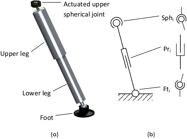
3.2.1 Concept 1: Actuated Upper Spherical Joint Leg (SPS)
The simplest change that can be made to the FreeHex to allow it to walk is to actuate the ball joint at the top of the leg by some means in order to position the leg. The prismatic joint that provides the telescopic action for machining remains largely unchanged, but is inverted such that the outer section is at the top of the leg and not the bottom. This is so that, whatever actuation method is selected, the components of the actuation system can be fitted to the outside of the upper part of the leg without risk of fouling as the leg extends and contracts. This new arrangement, illustrated in Figure 5 does not fit
straightforwardly into any of the established categories of walking robot leg and would require a novel mechanism to actuate the spherical joint; this concept cannot, therefore, be immediately utilised without consideration of alternatives.
Actuated upper spherical joint
Upper leg
Lower leg
Foot
Pri
Sphi
Fti
[image:15.612.148.471.449.690.2](a) (b)
16
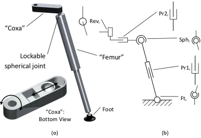
3.2.2 Concept 2: Femur Leg (RPSPS)
Based on the coxa and femur sections of an insect’s leg, a separate member is added to the top joint of the leg, allowing it to sweep through a path while the leg is held in a vertical position by a locking mechanism. This design falls within the gravitationally
decoupled category, so presents a more efficient mode of walking. The mechanism consists of a prismatic member inside a pin jointed member as illustrated in Figure 6. This design has the advantage that the upper spherical joint does not have to be fully actuated, but is simply locked and unlocked from the vertical position and plays no role while the robot is walking. While this reduces the number of actuators, it limits how well the leg’s position can be controlled and the available workspace as well as posing a considerable technical challenge in maintaining accuracy while allowing for a locking mechanism.
Lockable
spherical joint
“Coxa”
“Femur”
Foot
Pr1i
Sphi
Fti
Pr2i
Revi
“Coxa”: Bottom View
[image:16.612.117.510.354.624.2](a) (b)
Figure 6: Concept 2: Leg design with inclusion of a femur arrangement impression (a) and general layout (b)
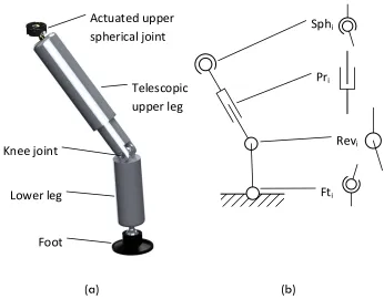
3.2.3 Concept 3: Knee Jointed Leg (SPRS)
The introduction of a knee joint (see Figure 7) to the first concept produces a leg
17 greater control over where the foot is placed, which is particularly useful when avoiding small obstacles. This would also permit a more natural, gravitationally decoupled gait if the upper leg were angled horizontally at the cost of an additional joint and actuator. However, this design has a drawback in the fact that the travel range of the prismatic joint is limited due to its reduced size within the leg, reducing the working volume of the PKM mechanism for machining. The introduction of the additional joints also adds inaccuracies to the system, affecting the quality of the machining. The knee joint would need to be
lockable to maintain accuracy in machining mode, increasing complexity also introducing errors.
Pri
Sphi
Fti
Revi
Actuated upper spherical joint
Foot
Telescopic upper leg
Knee joint
Lower leg
[image:17.612.103.449.313.583.2](a) (b)
Figure 7: Knee jointed leg impression (a) and general layout (b)
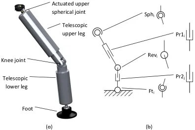
3.2.4 Concept 4: Hybrid Articulated Gravitationally Decoupled (AGD) Leg (SPRPS)
18 flexibility in terms of leg positioning. This arrangement is also capable of some very interesting gravitationally decoupled gaits, but would require a considerable amount of control hardware and complex control software.
Pr1i
Sphi
Fti
Revi
Pr2j
Actuated upper spherical joint
Foot Telescopic
lower leg
Telescopic upper leg
Knee joint
[image:18.612.99.495.165.429.2](a) (b)
Figure 8: Hybrid AGD impression (a) and general layout (b)
3.3
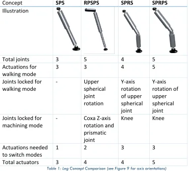
Concept Summary and Comparison
A comparison of the different concepts described above is given in Table 1. The criteria for comparison are as follows: ‘total joints’ corresponds to the total number of joints present in a single leg, including the spherical joint that attaches the foot to the leg. The Actuations for walking mode indicates the number of independent joint actuations
19 the leg. Since the configurations for the two modes are different, the number of actuations required to switch the mode of operation are also included; it is desirable to have as few actuations as possible in order to quickly and accurately begin and finish an operation.
Concept SPS RPSPS SPRS SPRPS
Illustration
Total joints 3 5 4 5
Actuations for walking mode
3 3 4 5
Joints locked for walking mode
- Upper spherical joint rotation Y-axis rotation of upper spherical joint Y-axis rotation of upper spherical joint Joints locked for
machining mode
- Coxa Z-axis rotation and prismatic joint
Knee Knee
Actuations needed to switch modes
1 2 3 3
[image:19.612.91.472.161.506.2]Total actuators 3 4 4 5
Table 1: Leg Concept Comparison (see Figure 9 for axis orientations)
20 should be avoided. Each individual joint may also introduce play into the system,
compromising the machining accuracy; thus, the total number of joints should be minimised. The actuations for walking mode refers to the maximum number of actuators that are required to actuate in order to move a leg during a single stage of a gait cycle. In order to utilise the robot in either walking or machining mode, some of the possible actuated or free joints (or axis-specific rotations thereof, in the case of spherical joints) must be restricted in order to correctly constrain the motion. Having to lock joints, however, is undesirable, as any backlash or wear due to interference restraints will introduce inaccuracies.
The number of actuations needed to switch modes offers a reflection of how rapidly the modus operandi can be changed from ‘walking’ to ‘machining’; it corresponds to the number of actuators that must be activated to achieve the transition. It is desirable to minimise this number in order to both simplify and speed up the transition process, reducing the overall complexity of the concept, though this factor alone is a relatively minor consideration.
SPRPS offers the best flexibility and walking speed but is most complex. Adding an
21 RPSPS was initially considered for further development, but due to the lack of a suitable method for locking the ball joints that preserved their positional accuracy, this concept was rejected. The concept also limited the range of positions that the feet could be placed in, reducing its ability to avoid obstacles.
In light of these considerations, SPS constitutes a concept that is simple, has no locking joints and can quickly switch from machining to walking mode and back and as such is the
concept chosen for further development.
4
Actuation Concepts
Once the overall leg joint layout has been defined, it is important to consider how the actuation can be achieved.
4.1
Requirements for Actuation
The chosen overall leg concept requires that the upper spherical joint be actuated, or more specifically, that the angle of rotation about the x and y axes of the leg(see Figure 9) must be accurately controllable and the position must be held, resisting a moderate moment (10Nm, see [35]) about the spherical joint in order to prevent collapse of the WalkingHex, particularly when fewer than six feet are on the ground; of course the selection of suitable actuators needs to be based on the construction of a particular overall design.
When considering the method for achieving the required actuation, the following factors are of importance.
The actuators must:
22 (ii) be compact, to reduce the risk of self-collision and thereby increase the
working volume
(iii) generate enough moment to hold the leg in any required position, including the possibility of taking a third of the total weight of the WalkingHex when the leg is touching the floor
(iv) be capable of disengaging or by other means permit the upper joint of the leg to rotate freely about the x- and y- axes whilst in machining mode while allowing for a small amount of uncontrolled rotation in the 𝑧𝐿-axis; this is to
allow for twist in the leg when acting as a Stewart platform, as the leg orientation doesn’t remain constant
(v) be lightweight so as not to increase greatly the overall mass of the hexapod and thereby adversely affect the dynamics for walking and machining
z
x y
q f
[image:22.612.209.395.350.537.2]zL
Figure 9: Orientation of spherical joint axes
4.2
Actuation Concepts
4.2.1 Concept 1: Parallel Linear Actuators
23
Figure 10: Parallel linear actuators concept
Non-captive linear motors contain an internal thread on the rotor, into which is inserted a threaded spindle. If the spindle is prevented from rotating, when the motor is active, the spindle moves linearly through the core of the motor.
In order to decouple the motion in these two directions, sliding joints mounted on the spherical joint are utilised. In order to disengage this mechanism, the spindles of the motors could have a magnet attached to one end in order to grip a receptacle on the sliding assembly – when the foot is on the ground, the actuator can be retracted, pulling the magnet out of its socket by brute force and freeing the leg. Once the machining operation is complete, the legs must be restored to their lengths so that the magnets can be
reinserted, which might prove tricky to coordinate and would provide no backup
reattachment mechanism for the purpose of safety. Alternatively, disengagement could be
Pr1i
Sph1i
Sph2i
Pr5i
Pr2i
Pr4i
Platform
Magnets Prismatic Joint
Spherical Joint
Motor
Leg
Structural Part
d
24 achieved utilising actuators containing a clutch (see Figure 11(b)); however this would require a bespoke motor construction and may compromise the achievable accuracy.
Motor casing and stator Rotor
Threaded spindle
Rotor Threaded spindle
4-jaw threaded clutch
[image:24.612.92.522.176.395.2](a) (b)
Figure 11: Sectioned view of a non-captive linear motor (a) and possible clutch mechanism (b)
The kinematics of this concept are very straightforward, since they can be derived using simple trigonometry and a high level of accuracy can be achieved by using precision linear motors.
However, this design is bulky and would render the space underneath the platform very cramped.
A simple prototype of this concept was produced in order to verify its functionality. It was found that actuation could be achieved with a limited level of accuracy and that the small diameter of the threaded motor spindle and its connection to the sliding elements
25
4.2.2 Concept 2: Perpendicular Linear Actuators
[image:25.612.89.521.287.591.2]Figure 12 presents a more compact mechanism that works on a similar principle to that of Parallel Linear Actuators. In this case, linear motors utilising spindle drives with guide rails that are in a vertical arrangement with pin-jointed members connecting them to the sliders on the leg. This layout allows for a neater arrangement of the legs beneath the platform and means that the guide rails take more of the force than the motor when a leg is in the most disadvantageous position, i.e. raised to a large angle.
Figure 12: Perpendicular linear actuators concept
A prototype of this concept was produced and it was found that the main drawback of this design lies in the complexity of the linkages, which means that any inaccuracies in
Pr1i Pr3i
Pr2i Pr4i
Rev1i Rev3i
Rev4i
Rev2i
Magnets
Revolute Joint
Gimbal Joint
Prismatic Joint
Spherical Joint
Motor
Leg
Structural Part
26 these joints will be amplified throughout the system. Also, there is nothing to prevent the leg from rotating about its axis, potentially leading to an uncontrolled degree of freedom.
4.2.3 Concept 3: Vertical Linear Actuators
[image:26.612.171.441.388.671.2]This mechanism utilises two non-captive linear motors seated inside spherical joints mounted inside the platform, spaced at a 90° interval in order to actuate the leg (Figure 13), with spindles attached via spherical joint couplings to a point along the leg. These spherical joints are located in a collar that would be locked in place during walking operation, but can be released and retracted up the leg when machining mode is required. This collar has a larger diameter than the top of the leg, so the leg is able to move freely for a specific range of angles of leg inclination before contact is made with the collar when it is retracted. The motor shafts are at a slight angle to the vertical when the leg is in the neutral position.
Figure 13: Vertical linear actuators concept
Sph4i Pr1i Sph2i
Sph1i
Sph3i
Pr2i
Sph5i Pr3i
Prismatic Joint
Spherical Joint
Motor
Leg
27 A number of simulations of the dynamics of this design were conducted using PTC Creo [36] and it was found that this concept fails to correctly constrain the z axis rotation of the leg and therefore produces an under-actuated system. There is also an issue with the use of spherical joints to contain the non-captive linear actuators: there is only the friction in the joint to keep the motor from rotating inside the spherical joint rather than producing linear motion. This could be overcome by replacing the spherical joints with gimbal joints, however, this design poses too many other problems to be worthy of further elaboration. An alternative version of this concept that addresses the issues by using three motors instead of two, spaced at 120° and attached around the diameter of the leg was proposed; however, this leads to a redundantly actuated system for which the motors would need to be driven very carefully in order to prevent damage to both the motors and the structure. This led to the development of a more feasible alternative, concept 4.
4.2.4 Concept 4: Three Wire Actuation
28
Figure 14: Three wire concept
This concept suffers from the same redundant actuation as the alternative version of concept 3; however, it is possible to compensate for this by utilising the information provided by the speed controllers to find the tension in the wires and ensure that the tension is properly maintained. Since the wires are only tensioned in the ‘pull’ direction, they can be slackened off to release the constraint; this is useful both for keeping the motors from ‘competing’ and for disengaging the actuation for machining mode. Herein lies the true beauty of this concept: there is no need to align any parts for re-engagement, there is no reliance on magnets or locking mechanisms and the mechanism can be
disengaged and re-engaged in any position. The kinematics for this concept are, however, not as straightforward as those for the parallel and perpendicular linear actuator concept
Pr3i
Pr1i
Pr2i
Sph1i
Platform Ball cable
attachment Prismatic Joint
Spherical Joint
Motor
Leg
Structural Part
29 and the motors are fitted to the leg, which, while producing a much more compact solution with a lower centre of mass, alters the dynamics of the leg motion by increasing their weight and may give rise to self-collisions by increasing their size.
4.3
Comparison of Actuation Concepts
[image:29.612.118.499.261.401.2]The four main concepts were ranked based on the requirements outlined in section 4.1 and weightings were applied, reflecting the importance of each attribute; the results of this are presented in Table 2.
Table 2: Decision matrix for main actuation concepts
Concept 1 suffered from issues with compactness and when considered in the context of the full hexapod, these issues make the concept very difficult to implement, although it is capable of very accurate control of the leg position, given high precision drives.
Concept 2 addresses the issue with space allocation under the hexapod, but introduces backlash and unwanted additional degrees of freedom, making it difficult to control accurately and heavy.
Concept 3 is very compact and light, but doesn’t disengage as well as the other concepts, as well as having unresolved issues with unwanted degrees of freedom, that rule out this concept.
Attribute Weight Value Weighted Value Value Weighted Value Value Weighted Value Value Weighted Value
Accuracy 8 3 24 2 16 1 8 4 32
Compactness 6 1 6 3 18 4 24 2 12
Actuation Force 4 4 16 3 12 2 8 1 4
Disengagement 10 2 20 3 30 1 10 4 40
Mass 2 3 6 1 2 4 8 2 4
13 12 12 13
72 78 58 92
4. Three Wires
Total Weighted Total
Design 1. Parallel Linear Actuators
2. Perpendicular Linear Actuators
30 In spite of the drawbacks in terms of kinematics, leg weight and leg size for concept 4, the three wire concept provides the most compact overall solution and the most simple and elegant method of disengagement. As such, this concept was chosen for development.
5
Theoretical Description of chosen solution
In order to utilise the chosen concept, a better theoretical understanding of the mechanism is required, in particular, the inverse kinematics for the leg. While the upper joint is in actuality a spherical joint, the required control methodology means that it should be effectively treated as a universal joint with centrally intersecting axes of rotation while in walking mode.
5.1
Inverse Kinematics
31
y
x z
q
f
Platform
Wire attachment plate
[image:31.612.104.537.72.371.2]l
Figure 15: Vector representation of leg system
The positions of each of the wire connection points are known in 3D space for any given pose of the leg and the magnitude of the vectors 𝑤𝑖 between each pair of points gives the length of the corresponding wire in order to achieve that pose:
32
(1)
The vector locations of the wire attachments to the platform with respect to the upper spherical joint are given by S:
(2)
This is subtracted from L, giving three column vectors corresponding to the wire positions in 3d space:
=
(3)
33
(4)
(5)
(6)
(4) - (6) give the inverse kinematics of the system: the length of the three wires in terms of the desired angles of inclination of the leg.
The forward kinematics of the leg can be determined utilising these equations; however, the analytical solution is non-trivial due to the trigonometric cross terms present in each of the equations. As such, and since they are not required for the control methodology utilised here, they are not a subject of discussion for this paper.
5.2
Verification of Inverse Kinematics
34 each wire were measured and compared against the values computed using the
kinematics. The results showed a maximum error of 1.04404E-09 m, which can safely be attributed to rounding errors within the software.
6
Realisation of Concept
6.1
Mechatronic Description
In order to achieve the required actuation, linear actuators were selected to tension the wires. This allows the wire to be pulled through a ‘pulley point’, lengthening or shortening the effective length of the wire, that is, the distance between the ‘pulley point’ and the upper attachment point. Linear actuators utilising a DC motor with a precision spindle drive are capable of very accurate linear positional control and high maximum thrust, making them suitable for this task.
The motor assembly chosen here for actuation of each wire was a Maxon 443981, comprised of:
a 2W brushed DC motor
a 3 stage gearbox with an approximate reduction of 84:1 a 5mm diameter, 2mm pitch ball screw spindle
a 512 Count-Per-Turn quadrature encoder
This lead to a combination with a resolution of 1/86,016mm and a maximum intermittent thrust of 403N on the output shaft.
35
Figure 16: Prototype of leg
A National Instruments RIO FPGA (Field Programmable Gate Array) board running at 40MHz provided a hardware interface for the control software, which was developed in LabVIEW and used a PD position controller along with the inverse kinematics to accurately actuate each of the three wires.
6.2
Control
To allow the system to be accurately controlled, a model (illustrated in Figure 17) was developed for the motors in order to define the motion characteristics. The motor characteristics presented in Table 3 were provided by the manufacturer; however, the damping of the system had to be determined experimentally.
Platform
Leg
Pr3
iPr1
iPr2
iSph1
iBall cable
attachment
36
Figure 17: Variables in motor system
Quantity Value
Resistance, R1 76.2Ω
Inductance, L1 2.61mH
Supply Voltage, V1 21V
Moment of inertia of rotor, J 86.6 × 10⁻⁹𝑘𝑔𝑚2
Electromotive constant, 𝒌 0.016268𝑉𝑠 𝑟𝑎𝑑−1
Damping ratio, b 3.76 × 10⁻⁶
Table 3: Motor characteristics
The motor can be modelled by the following two characteristic equations obtained from Newton’s Second Law and Kirchhoff’s Law respectively:
𝐽𝜃̈ 𝑡 + 𝑏𝜃̇ 𝑡 = 𝑘𝑖 𝑡
𝐿𝑑𝑖 𝑡
𝑑𝑡 + 𝑅𝑖 𝑡 = 𝑣 𝑡 − 𝑘𝜃̇ 𝑡
( 1 )
( 2 )
If these equations are transformed into Laplace domain and solved simultaneously (see [37]), the transfer function between the voltage and angular position of the motor can be found to be:
Θ 𝑠 𝑉 𝑠 =
𝑘
𝑠( 𝑅 + 𝐿𝑠 𝐽𝑠 + 𝑏 + 𝑘2)
[image:36.612.146.460.152.393.2]37 Inverse
Kinematics
PD Controller
Speed Controller
Encoder
Motor Linear distance to
rotary pulses
conversion
[image:37.612.121.491.72.154.2]-+
Figure 18: Control model for the system
A PD controller was designed utilising Simulink and the values of the proportional and derivative constants (𝐾𝑃and 𝐾𝐷) were tuned in order to optimise performance. The PD controller can be expressed as follows:
𝐾𝑃+ 𝐾𝐷( 𝑁 1 + 𝑁1𝑠)
where 𝑁 is the filter coefficient; 𝐾𝑃, 𝐾𝐷 and 𝑁 were found to be:
𝐾𝑃 = -6.6578 𝐾𝐷 = -0.042912
𝑁 = 332.64
38
Figure 19: PD controller step response
These values were translated into the LabVIEW FPGA control code for use in controlling the prototype. In order to regulate the tension in the wires, the system was pre-tensioned to a known tension each time the position was zeroed using the current drawn by each motor to estimate the respective tension in the wire. In order to limit the variance in tension, each move was completed by moving the leg through a number of intermediary positions determined using a cubic interpolation algorithm. The tension in the system cannot,
however, completely eliminate the rotation about the 𝑍𝐿-axis, which may give rise to some minor errors.
6.3
Experimental Results
A series of experiments were conducted in order to verify the accuracy and reliability of the control of the leg utilising a Co-ordinate Measuring Machine (CMM). The following methodology was utilised for obtaining the results:
39 foot for the purposes of measuring the position of the end of the leg. In order to define the axes of the system for the CMM, the position of the upper spherical joint was
measured to give the origin. The leg was then moved through an angle of 0.1745 rad in ϕ a measurement of the position of the ball was taken and a line was constructed through this point and the origin in order to define the y-axis, as illustrated in Figure 20.
y
z
x
CMMProbe Leg in
vertical position Reference
ball
Leg in inclined position
[image:39.612.145.464.219.640.2]CMM Bed
Figure 20: Using leg motion to define the y-axis
40 (1) Move leg to initial position
(2) Measure initial position of ball (3) Move the leg to required angle (4) Measure current position
(5) Repeat steps (3) and (4) for each set of angles required
(6) Subtract initial position from each subsequent position to obtain relative coordinates
(7) Use 𝜃 = asin (𝑥𝑙) 𝑎𝑛𝑑 𝜙 = asin (𝑦𝑙) to obtain angles
(8) Compare desired angles with obtained angles
The series of points used in these experiments was as follows:
Experiment
# θ /rad ϕ /rad
1 0 0
2 0.1745323 0
3 0 0
4 -0.1745323 0
5 0 0
6 0 0.174533
7 0 0
8 0 -0.17453
9 0 0
41
11 0 0
12 -0.523599 0
13 0 0
14 0 0.523599
15 0 0
16 0 -0.5236
17 0 0
18 0.174533 0.174533
19 0 0
20 0.174533 -0.17453
21 0 0
22 -0.174533 0.174533
[image:41.612.205.405.70.395.2]23 0 0
Table 4: List of experimental co-ordinates
6.3.1 Accuracy
The results of the experiments (Figure 21) show that the system is capable of rotating the leg to a required position with a good degree of accuracy. The mean error in θ was found to be 0.01171 and in ϕ , -0.006222 rad (4 s.f.), indicating a greater degree of accuracy in the ϕ direction.
42 however, they are included in the standard result set (making for a total of 27 points and 26 transitions).
Figure 21: Plot of desired and experimental co-ordinates for experiments
-0.6 -0.4 -0.2 0 0.2 0.4 0.6
-0.6 -0.4 -0.2 0 0.2 0.4 0.6
Phi
[rad]
Theta [rad]
43
Figure 22: RMS angular error for the transition between each experimental position (e.g. Euclidean error in distance moved between point 1 and point 2)
6.3.2 Error Analysis
The results presented above show that this system is capable of controlled motion of a degree of precision that is more than suitable for the intended application, i.e. walking. For a machining operation, the hexapod will be referenced against the job, so this is not relevant. The mean RMS transition error was found to be 5.64%; however, the presence of some anomalous results suggests that this figure could be reduced by improving the control mechanisms.
Part of the error in this system may be due to the redundantly actuated nature of the three wire system. In order to get around this, it may be possible to implement a different control methodology in order to actively maintain constant tension in the system. This would involve actuating two of the three wires utilising the inverse kinematics and the third using a current based control, controlling the overall tension in the system; this would, however,
0 0.01 0.02 0.03 0.04 0.05 0.06
1 2 3 4 5 6 7 8 9 10 11 12 13 14 15 16 17 18 19 20 21 22 23 24 25 26
R
M
S Error
[rad]
44 not help to account for the effect of minute rotations of the leg about the 𝑍𝐿-axis or
prevent inaccuracies from entering the system due to drift.
Another issue present in the current system is that there is currently no automated method of zeroing the leg, meaning that, by itself, the leg cannot be accurately calibrated but must be aligned manually using measuring tools. An inbuilt system for measuring the rotation of the upper spherical joint might provide for a more robust control methodology; there is however, no suitable system currently available.
In summary, considering a leg length of 300mm and an angle of inclination of 0.1745 rad, the position of a foot attached to the end of the leg can be determined to within 2.953 mm using this experimental arrangement of wires and actuators.
7
Conclusions
The industrial need to perform complex multi-axis processing in-situ large structures/hazardous environments has led to research for the developments of
mobile/walking machine tools. To address this need, this paper reports on the design and control of a single leg of a Walking free-leg Hexapod structure (WalkingHex) that represents a key step forward from the previously reported Free-leg Hexapod configuration.
As such, the main contributions of the paper can be summarised as follows:
- Identification of a suitable original joint layout for the WalkingHex leg that allows for operation both as a walking robot and a PKM, while maintaining the same PKM structure and potential accuracy as the FreeHex.
45 disengagement. This is achieved utilising a three wire mechanism, whereby three wires, equispaced around the leg are tensioned and slackened in a synchronised way during walking to control the inclination of the leg, while remaining slack during machining operation.
- Analytical derivation of the inverse kinematics required in order to control such a system and the verification of their accuracy both by simulation in PTC Creo and physical prototype.
- Description of a prototype of the actuation mechanism and experimental verification of its accuracy, with mean RMS error found to be 5.64%.
8
Further work
The leg actuation mechanism described in this paper will be utilised in building the WalkingHex, a robotised machine tool for inspection and repair in hazardous and inaccessible environments.
9
Acknowledgment
The authors would like to acknowledge Aitor Olarra for his suggestions regarding actuation concepts.
46
10
References
[1] D. C. H. Yang and T. W. Lee, "Feasibility Study of a Platform Type of Robotic Manipulators from a Kinematic Viewpoint," Journal of Mechanisms
Transmissions and Automation in Design, vol. 106, pp. 191-198, 1984.
[2] P. J. Houdek, "Design and Implementation Issues for Stewart Platform
Configuration Machine Tools," Mechanical Engineering, Boston Universtiy, 1997. [3] H. H. Yi-Ping Hsin, Jin Nishikawa, Scott Coakley, Kunitomo Fukai, Wen-Hou Ma,
Bausan Yuan, "Hexapod Kinematic Mountings for Optical Elements and Optical Systems Comprising Same," 2006.
[4] A. Ghuman, J. Lowe, M. Rosso, and K. Sanborn, "Manufacturing Assembly Line and a Method of Designing a Manufacturing Assembly Line," United States Patent, 2005.
[5] H. Yang, S. Krut, C. Baradat, and F. Pierrot, "Locomotion approach of REMORA: A reconfigurable mobile robot for manufacturing Applications," in Intelligent
Robots and Systems (IROS), 2011 IEEE/RSJ International Conference on, 2011, pp.
5067-5072.
[6] M. Guy, "Aircraft fuselage drilling and riveting machine tool has suction pads associated with a movable multi-arm tool displacement and orientation frame whose lower arm ends are also fitted with suction pads," France Patent
FR2809034, 2001-11-23, 2001.
[7] M. Denton. (2008, 01/08). Hexapod Robot CNC router. Available: http://www.hexapodrobot.com/forum/viewtopic.php?f=14&t=12
[8] J. A. T. Machado and M. F. Silva, "An Overview of Legged Robots," in Proceedings
of the MME 2006-International Symposium on Mathematical Methods in Engineering, Cankaya, Ankara, Turkey, 2006.
[9] Anon., "Logistical Vehicle Off-Road Mobility, Project TCCO 62-5," U.S. Army Transportation Combat Developments Agency, Fort Eustis, Va.1967.
[10] P. G. de Santos, M. A. Armada, and M. A. Jimenez, "Ship building with ROWER,"
Robotics & Automation Magazine, IEEE, vol. 7, pp. 35-43, 2000.
[11] D. Stewart, "A Platform with Six Degrees of Freedom," Proceedings of the
Institution of Mechanical Engineers, vol. 180, pp. 371-386, June 1, 1965 1965.
[12] J. M. Allen, D. A. Axinte, and T. Pringle, "Theoretical analysis of a special purpose miniature machine tool with parallel kinematics architecture: free-leg hexapod,"
Proceedings of the Institution of Mechanical Engineers, Part B: Journal of Engineering Manufacture, vol. 226, pp. 412-430, March 1, 2012 2012.
[13] D. A. Axinte, J. M. Allen, R. Anderson, I. Dane, L. Uriarte, and A. Olarra, "Free-leg Hexapod: A novel approach of using parallel kinematic platforms for developing miniature machine tools for special purpose operations," CIRP Annals -
Manufacturing Technology, vol. 60, pp. 395-398, 2011.
[14] A. Olarra, J. M. Allen, and D. A. Axinte, "Experimental evaluation of a special purpose miniature machine tool with parallel kinematics architecture: Free leg hexapod," Precision Engineering-Journal of the International Societies for
47
[15] D. Karimi and M. J. Nategh, "A Study on the Quality of Hexapod Machine Tool's Workspace," World Academy of Science, Engineering and Technology, 2009. [16] D. C. Kar, "Design of Statically Stable Walking Robot: A Review," Journal of
Robotic Systems, vol. 20, pp. 671-686, 2003.
[17] M. Kaneko, M. Abe, and K. Tanie, "A hexapod walking machine with decoupled freedoms," Robotics and Automation, IEEE Journal of, vol. 1, pp. 183-190, 1985. [18] H. Adachi, N. Koyachi, T. Nakamura, and E. Nakano, "Adaptive gait for quadruped
walking robot using force sensor," in Proceedings of the Third International
Conference on Intelligent Autonomous Systems, IAS, 1993, pp. 54-63.
[19] H. Adachi, N. Koyachi, and E. Nakano, "Mechanism and control of a quadruped walking robot," Control Systems Magazine, IEEE, vol. 8, pp. 14-19, 1988. [20] R. A. Liston and R. S. Masher, "A versatile walking truck," presented at the
Proceedings of the Transportation Engineering Conference, Institution of Civil Engineers, London, 1968.
[21] M. Raibert, K. Blankespoor, G. Nelson, and R. Playter, "Bigdog, the rough-terrain quadruped robot," in Proceedings of the 17th World Congress, 2008, pp. 10823-10825.
[22] C. A. Klein and R. L. Briggs, "Use of active compliance in the control of legged vehicles," Systems, Man and Cybernetics, IEEE Transactions on, vol. 10, pp. 393-400, 1980.
[23] R. McGhee, C. Chao, V. Jaswa, and D. Orin, "Real-time computer control of a hexapod vehicle," in Third Symposium on Theory and Practice of Robots and
Manipulators, 1978, pp. 323-339.
[24] F. Pfeiffer, J. Eltze, and H.-J. Weidemann, "The TUM-walking machine,"
Intelligent Automation & Soft Computing, vol. 1, pp. 307-323, 1995.
[25] M. H. Showalter, "Work space analysis and walking algorithm development for a radially symmetric hexapod robot," Virginia Polytechnic Institute and State University, 2008.
[26] J. Bares, M. Hebert, T. Kanade, E. Krotkov, T. Mitchell, R. Simmons, and W. Whittaker, "Ambler: An autonomous rover for planetary exploration," Computer, vol. 22, pp. 18-26, 1989.
[27] T. G. Bartholet, "Odetics makes great strides," Nucl Eng Int pp. 37-38, 1985. [28] M. Agheli, L. Qu, and S. S. Nestinger, "SHeRo: Scalable hexapod robot for
maintenance, repair, and operations," Robotics and Computer-Integrated
Manufacturing, vol. 30, pp. 478-488, 2014.
[29] A. Rakich, M. Blundell, G. Pentland, R. Brunswick, T. Ferguson, and J. Waltho, "The SkyMapper wide field telescope," 2006, pp. 62670E-62670E-9.
[30] O. C. Martin, J. E. Muelaner, Z. Wang, A. Kayani, D. Tomlinson, P. G. Maropoulos, and P. Helgasson, "Metrology enhanced tooling for aerospace (META): A live fixturing Wing Box assembly case study," in 7th International Conference on
Digital Enterprise Technology, 2011, pp. 83-92.
48
[32] J. E. McInroy, "Dynamic modeling of flexure jointed hexapods for control purposes," in Control Applications, 1999. Proceedings of the 1999 IEEE
International Conference on, 1999, pp. 508-513.
[33] A. Rushworth, S. Cobos-Guzman, D. Axinte, and M. Raffles, "Pre-gait analysis using optimal parameters for a walking machine tool based on a free-leg hexapod structure," Robotics and Autonomous Systems, vol. 70, pp. 36-51, 8// 2015.
[34] G. E. Kirk, "Concept Generation," Nottingham, 2009.
[35] A. G. A. Rushworth, S. Cobos-Guzman, D. Axinte, and M. Raffles, "Pre-Gait Analysis using Optimal Parameters for a Walking Machine Tool based on a Free-leg Hexapod Structure," Robotics and Autonomous Systems, 2014.
[36] (2013). PTC Creo Parametric. Available:
http://www.ptc.com/product/creo/parametric
[37] R. Babuška and S. Stramigioli, "Matlab and Simulink for modeling and control," Technical report, Delft University of Technology1999.
![Figure 2: Articulated legged walkers: GE Walking Truck [20] (a) and TUM Walking Machine [24] (b)](https://thumb-us.123doks.com/thumbv2/123dok_us/8657845.374687/8.612.112.506.67.272/figure-articulated-legged-walkers-walking-truck-walking-machine.webp)
![Figure 3: Ambler Circulatory Walker [26] (a) and a generic 2-Dimensional pantographic mechanism (b)](https://thumb-us.123doks.com/thumbv2/123dok_us/8657845.374687/9.612.106.519.302.457/figure-ambler-circulatory-walker-generic-dimensional-pantographic-mechanism.webp)
![Figure 4: WalkingHex Design Process Model (Based on ‘The Generic Design Process Model’ [34])](https://thumb-us.123doks.com/thumbv2/123dok_us/8657845.374687/12.612.211.405.145.679/figure-walkinghex-design-process-model-generic-design-process.webp)