A Thesis Submitted for the Degree of PhD at the University of Warwick
http://go.warwick.ac.uk/wrap/3899
This thesis is made available online and is protected by original copyright. Please scroll down to view the document itself.
Hybrid supracolloidal structures
through interface driven assembly
By
Catheline A. L. Colard
A thesis submitted in fulfilment of the requirements for the
degree of Doctor of Philosophy in Chemistry
University of Warwick, Department of Chemistry
Figures ... viii
Tables ... xiii
Acknowledgement ...xv
Declaration ... xviii
Abstract ... xix
Abbreviations ... xxi
Chapter I. General introduction ...1
I.1. Interface and colloid science1...2
I.2. Stabilisation of lyophobic colloids...3
I.2.1. Electrically charged colloids...4
I.2.2. Sterically stabilised colloids ...6
I.2.3. Depletion effect...7
I.2.4. Image charge effect...8
I.3. Fabrication of supracolloidal structures...9
I.4. Interaction mechanisms for the preparation of solids-stabilised latex particles ...10
I.4.1. Particle wettability at liquid-liquid interfaces...11
I.4.2. Colloidal assembly by controlled heterocoagulation ...15
I.4.3. Haloing stabilisation ...16
I.5. Objectives and outline of the thesis ...17
I.6. References...21
Chapter II. Laponite clay – poly(vinyl esters) latexes prepared via miniemulsion polymerisation ...24
II.1. Introduction...25
II.2. Experimental ...30
II.2.3. Laponite stabilised poly(vinyl laurate) latexes in
miniemulsion polymerisation...31
II.3. Results and discussion ...33
II.3.1. Experimental restrictions in alkaline conditions: Case of vinyl acetate monomer ...34
II.3.2. Poly(vinyl laurate)/clay latexes...35
II.3.2.1. Thermal and shear stability ...35
II.3.2.2. Investigation of potential aqueous phase events ...36
II.3.2.3. Effect of the concentration in Laponite clay on the latex particle size...38
II.4. Conclusions...44
II.5. References...46
Chapter III. Solids-stabilised emulsion droplets for the preparation of silica-armoured polymer latexes...48
III.1. Introduction...49
III.2. Experimental ...53
III.2.1. Materials ...53
III.2.2. Equipment ...54
III.2.3. Preparation and stability of solids-stabilised emulsions ...54
III.2.4. Preparation of Ludox-stabilised polystyrene latexes in miniemulsion polymerisation via liquid-liquid interfacial stabilisation ...55
III.2.5. Preparation of Ludox stabilised poly(styrene-co-vinyl pyridine) latexes in miniemulsion polymerisation via heterocoagulation assembly ...56
III.2.6. Solids-stabilised poly(vinyl acetate) latex in suspension polymerisation via liquid-liquid interfacial stabilisation ...57
III.3. Results and discussion ...58
III.3.1. Energy profile of a spherical particle at a vinyl acetate – water interface...58
III.3.2. Wetting of silica particles at oil – water interfaces for the stabilisation of emulsion droplets ...60
polymerisation...65
III.3.5. Towards high emulsified contents ...77
III.3.6. Solids-stabilised latexes of poly(vinyl acetate) in suspension polymerisation ...83
III.4. Conclusions...85
III.5. References...87
Chapter IV. Silica-armoured poly(vinyl acetate) latexes made using solids-stabilised emulsion polymerisation...89
IV.1. Introduction...90
IV.2. Experimental ...93
IV.2.1. Materials ...93
IV.2.2. Equipment ...93
IV.2.3. Typical solids-stabilised emulsion polymerisation ...94
IV.2.4. Typical procedure of disc centrifugation measurements ...96
IV.3. Results and discussion ...98
IV.3.1. Optimisation of the pH for the synthesis of poly(vinyl acetate) latex particles armoured with silica nanoparticles...98
IV.3.2. Silica-stabilised poly(vinyl acetate) latexes with increased overall solids-content ...100
IV.3.3. Influence of the silica-to-monomer ratio in our solids-stabilised system ...101
IV.3.4. Unravelling the mechanistic of the solids-stabilised emulsion polymerisation process ...103
IV.3.4.1. Preparation of solids-stabilised latexes under monomer starved and non-starved regimes ...104
IV.3.4.2. Investigation on the mechanism of particle formation in solids-stabilised latexes using disc centrifugation ...107
Disc centrifugation for quantitative analysis...107
Theoretical model to determine the concentration of nanoparticles in the water phase ...109
Emulsion polymerisations carried out in presence of silica nanoparticles ...112
IV.4. Conclusions...120
Stability of silica-armoured poly(vinyl esters) latexes, production of
powders and their application in tile adhesive formulations ...122
V.1. Introduction...123
V.2. Experimental ...124
V.2.1. Materials ...124
V.2.2. Equipment ...124
V.2.3. Typical procedure for the sedimentation tube ...125
V.2.4. Standard conditions of spray-drying ...125
V.2.5. Standard test for tile adhesive application ...125
V.3. Results and Discussion ...126
V.3.1. Product properties ...126
V.3.1.1. Study of the colloidal stability via a sedimentation method 129 V.3.1.2. Thermal analysis...131
V.3.2. Production of redispersible powders by spray-drying the latexes...134
V.3.3. Testing the redispersible powders in cement-based tile adhesives formulations...139
V.4. Conclusions...140
V.5. References...141
Chapter VI. Highly porous nanocomposite reinforced open-cell foams through freeze-drying mixtures of colloids and their application as gas sensors ....142
VI.1. Introduction ...143
VI.2. Experimental ...146
VI.2.1. Materials...146
VI.2.2. Equipment ...147
VI.2.3. Preparation of poly(vinyl laurate) latexes via miniemulsion polymerisation...148
VI.2.4. Preparation of polystyrene nanoparticles via emulsion polymerisation...148
VI.2.5. Preparation of composite foams...148
VI.2.6. Calcination of composite foams...149
foams to be used as gas sensors ...151
VI.2.9. Testing hybrid carbon black/silica/polymer foams as gas sensors ...151
VI.3. Results and discussion ...152
VI.3.1. Colloidal dispersion of multi-components ...152
VI.3.2. Formation of porous material using the ice-templating strategy 151 VI.3.3. Reinforcement with “small-hard” nanoparticles...155
VI.3.4. Entrapment of “large” polymer particles ...158
VI.3.5. Preparation of inorganic foams with super-high porosity...159
VI.3.6. Versatility of the process using different types of “hard” nanoparticles ...161
VI.3.7. Conducting foams as gas sensors...161
VI.4. Conclusions ...164
VI.5. References:...165
Chapter VII. Conclusion and outlook for industrial applications...167
Appendix A. Characterisation of colloids...173
A.1. Gravimetry ...173
A.2. Electrophoretic light scattering ...174
A.3. Dynamic light scattering ...176
A.4. Imaging by electron microscopy...179
A.4.1. Scanning electron microscopy ...180
A.4.2. Transmission electron microscopy ...181
A.5. References...182
Appendix B. Complement to Chapter III on Laponite clay – poly(vinyl esters) latexes...183
B.1. Determination of monomer conversion Xm by 1H NMR spectroscopy ...183
B.2. Formulation of all the poly(vinyl laurate)-Laponite clay latexes ...186
B.3. Hydrolysis of vinyl acetate monomer emulsified in Laponite-clay dispersion: pH measurements ...188
B.4.2. Semi-empirical model correlating average latex particle size with the amounts of clay and monomer proposed by Bon and Colver2...190 B.5. References...193
Appendix C. Complement to Chapter III on solids-stabilised
droplets for the preparation of silica-armoured polymer latexes ...194
C.1. Formulation of Ludox-stabilised latexes ...194
C.2. Hand-shaking tests for the formation of solids-stabilised emulsions with Ludox TM-40 silica nanoparticles ...195
C.3. Fumed silica powders as solids-stabiliser for o/w and w/o emulsions of vinyl acetate ...197
Appendix D. Complement to Chapter IV on silica-armoured
poly(vinyl acetate) latexes made using solids-stabilised emulsion polymerisation 200
D.1. Formulation and kinetics of Ludox-poly(vinyl esters) latexes ...200
D.2. Armoured structure of the Ludox-poly(vinyl acetate) latexes by transmission electron microscopy...202
D.3. Disc centrifugation particle sizing measurements ...203
D.3.1. Principle of disc centrifugation particle sizing1...203 D.3.2. Data analysis to determine the concentration in
nanoparticles using disc centrifugation...205
D.3.3. Reproducibility and variation between gradient fluids
for disc centrifugation measurements ...210
D.3.4. Stability of the gradient fluid ...211
D.4. References...211
Appendix E. Complement to Chapter V on the stability of silica-armoured poly(vinyl esters) latexes, production of powders and their application in tile adhesive formulations ...213
E.1. Formulation of Ludox-poly(vinyl esters) latexes ...213
E.2. Standard dry formulation for tile adhesives...214
E.3. Determination of slip and workability of the prepared tile adhesive pastes...215
Figure I-1. Schematic representation of the total potential energy (red line) obtained by adding the van der Waals attraction potential, Va, and the electrostatic and Born repulsion potentials,Vr, as a function of distance between two spherical particles. The height of the repulsive barrier indicates system stability...6
Figure I-2.Schematic representation of a solid spherical particle of radiusR
sitting at the interface of φ1 and φ2 a distance Z from the centre C.
2 1 2
1, ,
p p are the surface/interfacial tensions between the particle and φ1,
the particle and φ2 and the two phases respectively and θ is the three-phase
contact angle. ...12
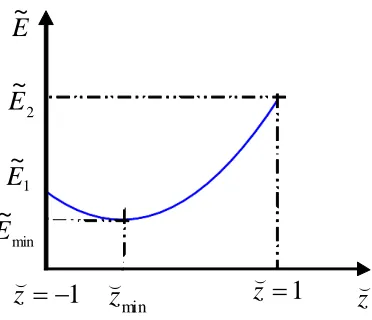
Figure I-3. Potential energy curvature of a solid particle leaving the
interface to go in φ1 ( 1 ~
E ) or in φ2( 2 ~
E ) where, zminis the vertical coordinate of the centre c, position of the particle at the liquid-liquid interface, at minimal energy (E~min). ...13
Figure II-1. Cartoon of the formation of armoured oil-in-water
miniemulsion droplets of monomer using clay platelets as stabiliser (step (2)). 33
Figure II-2.Monomer conversion followed by1H NMR spectroscopy in the presence of a water soluble scavenger ([], 124) and without ([ ],
CC-1-123). 38
Figure II-3. Graph of the hydrodynamic average diameter dz of the clay-stabilised poly(vinyl laurate) latexes versus the overall amount of clay platelets [] (and calculated values from the fitted model [▲], see Figure II-4). 40
Figure II-4. The calculated excess concentration of Laponite clay discs supposedly remaining in the aqueous phase, Cexcess, versus the initial overall concentration in clay particles in water, C0, for the clay-stabilised poly(vinyl laurate) latexes. ( ) is the corresponding linear fit of equation Cexcess = (1-0.1741) C0 – 0.0030. For comparison, ( ) and ( ) were the linear fits found by Bon and Colver in the case of clay-stabilised polystyrene latexes of equationsCexcess= (1-0.2438) C0– 0.0008 and Cexcess = (1-0.3076)C0 – 0.0006, using 4 and 8 wt% of hexadecane based on monomer, respectively.34 42
Figure II-5. Hydrolysis reaction scheme of vinyl laurate monomer in alkaline medium leading to the formation of sodium laurate and acetaldehyde.43
Figure II-6. Cartoon of the formation of miniemulsion droplets of vinyl laurate in the presence of clay platelets as stabiliser (step (2)). 44
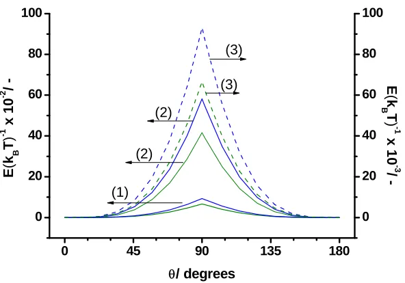
Figure III-1. Dependence of the free energy E, required to force one particle to leave a vinyl acetate – water interface when pushed in the most wettable phase, divided by its thermal energy (Brownian motion kBT), on contact angle θ. Particle of (1) 10 nm in diameter, (2) 25 nm in diameter and (3)
100 nm in diameter. Blue and green curves at T = 20 ºC (σ1-2= 24.0 dyne cm-1)
TM-40 colloidal silica dispersions...62
Figure III-3. Photographs of a 20 wt% Ludox TM-40 colloidal silica sol, gelled at pH 3.0 and not gelled at pH 1.8...63
Figure III-4. Photograph of a gelled solids-stabilised o/w emulsion of styrene monomer (40 wt%, oil soluble dye hostasol) using Ludox TM-40 as stabiliser (40 wt%) at pH 3.0. ...64
Figure III-5.SEM images of Ludox colloidal silica grades (A) TM-40 (d TM-40 (SEM) = 24.06 nm), (B) HS-40 (dHS-40 (SEM) = 13.66 nm), and (C) SM-30 (dSM-30(SEM) = 7.39 nm). Scale bars 100 nm. ...66
Figure III-6. SEM images of Ludox-polystyrene latexes prepared via solids-stabilised miniemulsion polymerisation: (A) Ludox TM-40 (CC-1-199), (B) Ludox HS-40 (CC-1-148), (C) Ludox SM-30 (CC-1-147). All scale bars 200 nm. ...67
Figure III-7. Spherical particle of radius Rpart resting at a liquid-liquid interface with a contact angle θ. Tensions σ1-2, σp-1, σp-2 correspond to the tensions between phase 1 – 2, particle – phase 1, and particle – phase 2; τ is the
line tension acting along the particle – phase 1 – phase 2 contact line...69
Figure III-8. Graph of the average diameters of the armoured polymer particles (dz (DLS) from dynamic light scattering measurements and d (SEM) from SEM image analyses) versus one over the average radius of the Ludox stabiliser used, Rpart (determined by SEM image analyses). Equations of linear fits are: dz(DLS) = 345.35R-1 + 83.89 andd (SEM) = 255.98R-1+ 84.17 with R2of 0.988 and 0.999 respectively. ...71
Figure III-9. SEM image of Ludox(TM-40)-polystyrene latex prepared via solids-stabilised miniemulsion polymerisation (CC-1-114). Scale bar 100 nm. 72
Figure III-10. SEM image of polystyrene latex particles, prepared in miniemulsion polymerisation using Ludox TM-40 as stabiliser, after disintegration of the armoured shell by addition of SDS surfactant (at a concentration of 5 times the CMC). Scale bar 200 nm...73
Figure III-11. SEM image showing the hedgehog morphology of hybrid poly(styrene-co-4-vinyl pyridine) latex particles prepared in miniemulsion polymerisation using Ludox TM-40 at high pH (CC-1-191). Scale bar 100 nm. ...74
Figure III-12. TEM images of colloidal silica (Ludox TM-40) armoured polystyrene latex particles (batch 1) prepared in miniemulsion polymerisation at pH ~3. Scale bars: (A) 50 nm and (B) 100 nm. ...75
Figure III-13. Example of analysis of packing geometries from an SEM image of a Ludox TM-40 armoured polystyrene latex: yellow, green, blue, and red coloured particles having 4, 5, 6 and 7 neighbours, respectively. Scale bar 100 nm. ...76
Figure III-14. Optical microscopy picture of a diluted emulsion of styrene in water stabilised with Ludox TM-40 nanoparticles prepared with an
in a square geometry (A), and representation of solids-stabilised o/w droplets: adherence of the silica nanoparticles at the oil – water interface with a contact angle of 90 º (B). ...81
Figure III-16. Graph of the solids-stabiliser to oil weight ratio versus the droplet diameter for spherical stabilisers of diameter of 25 nm (green curve), 15 nm (brown curve) and 8 nm (blue curve). ...83
Figure III-17. SEM micrographs of Ludox(TM-40)-poly(vinyl acetate) latex prepared via solids-stabilised suspension polymerisation (CC-2-344). Scale bars (A) 20 µm, (B) 2 µm and (C) 200 nm. ...85
Figure IV-1. SEM images of Ludox TM-40 stabilised PVAc latexes
prepared in emulsion polymerisation. (A) lower magnification showing
relatively narrow particle size distribution (latex CC-2-342, scale bar: 2 μm). (B)
and (C) zoom-in showing the close-packing of the silica nanoparticles on the surface at both pH 3.0 (latex CC-2-342) and 5.5 (latex CC-3-355), respectively (scale bars: 200 nm). ...100
Figure IV-2. SEM images of Ludox TM-40 stabilised PVAc latex prepared in batch emulsion polymerisation for a low silica-to-monomer ration of 0.22
(cc-3-379). Scale bars 2 μm and 200 nm, left and right respectively. ... 102 Figure IV-3. Average particle diameter, dz (top), and dispersity, DI, (bottom) versus the silica-to-polymer ratio throughout the (Ludox TM-40)-stabilised emulsion polymerisation of vinyl acetate. VAc fed for [] starved
conditions (exp. cc-3-357) and [■] non-starved conditions (exp. cc-3-371). ... 105 Figure IV-4.SEM images of a Ludox(TM-40)-stabilised poly(vinyl acetate) latex prepared in semi-batch emulsion polymerisation in starving condition of monomer (exp. cc-3-357): silica-to-polymer ratios of 0.22 (framed micrograph) and 0.07. Scale bars 500 nm. ...106
Figure IV-5.Representation of a solids-stabilised particle of hydrodynamic diameterdzand actual diameterβdzwhereβis a correcting factor (see text). The nanoparticles of silica are assembled on sphere of diameter (βdz–dsilica) and area Apolym...110
Figure IV-6. SEM images of latexes prepared in batch emulsion
polymerisation in presence of Ludox TM-40 colloidal silica. [a] PVPiv latex with a silica:monomer ratio of 0.44 (exp. cc-3-390). [b] PVAc latex with a silica:monomer ratio of 0.44 (exp. cc-3-381) and [c] PVAc latex with a silica:monomer ratio of 1.04 (exp. cc-2-345E). Scale bars 200 nm. ...114
Figure IV-7. The measured concentration of silica nanoparticles in the water phase, C, versus monomer conversion, Xm, as measured by quantitative disc centrifugation. [○] Solids-stabilised emulsion polymerisation of vinyl
acetate (13.0 wt%) at 5.8 wt% of silica nanoparticles. [×] Emulsion polymerisation of vinyl pivalate (13.1 wt%) in presence of 5.8 wt% silica nanoparticles. (Exp cc-3-381 and cc-3-390 in Table IV-5, respectively)...116
symbols were excluded in linear fit. ...117
Figure IV-9. The measured concentration of silica nanoparticles in the water phase,C, versusXm2/3for the solids-stabilised emulsion polymerisation of vinyl acetate (13.0 wt%) at 5.8 wt% of silica nanoparticles (cc-3-381, Table IV-5). Linear fit yields:C= 3.46 (±0.07) × 1015– 6.01 (± 0.28) × 1015Xm2/3(r2= 0.98). Closed symbols were excluded in linear fit...119
Figure V-1. SEM images of silica-stabilised PVAc latexes prepared in emulsion polymerisation: (A) using Ludox TM-40 silica (exp. cc-3-379), (B) using Ludox SM-30 silica (exp. cc-3-410). Both scale bars 200 nm. 129
Figure V-2.Photographs of the sedimentation tube for experiment cc-3-413
after 24 hours. 130
Figure V-3. SEM image showing the destruction of the armouring layer of silica nanoparticles around the PVAc latex particles by increasing the pH (exp. cc-3-373B, after 20 days at pH 11.0). Scale bar 200 nm. 131
Figure V-4.DSC analysis of latex cc-3-379. 132
Figure V-5. Scheme showing the different parts of the laboratory
spray-drier used and the powder flow. 136
Figure V-6. SEM images of powders obtained from spray-drying silica-stabilised PVAc latexes prepared in emulsion polymerisation: (A) using Ludox TM-40 silica (exp. cc-3-379), (B) using Ludox SM-30 silica (exp. cc-3-410).137
Figure V-7. Laser diffraction analysis of the dry powder obtained from spray-drying latex cc-3-379; particle size distributions in volume (top) and
number (bottom). 138
Figure VI-1. SEM images of composite foams obtained after subsequently freezing a waterborne mixture of colloids and, freeze-drying (A and B) or drying (C and D) the sample (“hard” silica nanoparticles (Ludox TM-40) and larger “soft” PVL latex: mass ratio of silica/polymer = 4.33 and overall solid contents of the samples = 24.7 wt%). ...154
Figure VI-2. SEM images of composite foams obtained after freeze-drying a waterborne mixture of colloids (“hard” silica nanoparticles (Ludox TM-40) and larger “soft” PVL latex: mass ratio of silica/polymer = 4.33 and overall solid contents of the samples = 24.7 wt%). The red arrows show the phenomenon of heat transfer; the direction going from smaller to larger pores.
Scale bars 10 μm. ... 155 Figure VI-3. SEM images of polymeric foams obtained after freeze-drying a waterborne mixture of “hard” silica nanoparticles (Ludox TM-40) and larger “soft” poly(vinyl laurate) latexes at increasing amounts of silica nanoparticles. Mass ratios of silica/polymer are A = 0, B = 0.22, C = 0.38, D = 0.46, E = 2.22. Overall solid contents of the samples are: A = 9.3 wt%, B = 12.1 wt%, C = 13.0 wt%, D = 13.6 wt%, E = 19.7 wt%...156
200 nm. ...157
Figure VI-5. Cryo-SEM image of nanocomposite polymer foam obtained after freezing a mixture of a PVL latex and Ludox silica nanoparticles at -210 °C with silica/polymer ratio and total solids content (wt%) of 0.54 and 12.7, respectively. The image was taken after partial sublimation of the ice. Scale bar 300 nm. ...158
Figure VI-6. SEM images of silica porous structures prepared from (A) drying a 10 wt% Ludox silica sol, and from (B) successively freeze-drying and calcining a PVL-Ludox sol of about 10 wt% in silica and 7 wt% of
PVL (B). Scale bars 10 μm. ... 160
Figure VI-7. SEM images of composite-PVL foams reinforced with
Laponite clay (left, scale bar 10 µm), aluminum oxide (middle, scale bar 20 µm) and polystyrene nanoparticles (right, scale bar 10 µm). ...161
Figure VI-8. Picture of the conducting foam wired to two electrodes for studying the influence of toluene vapours on the resistance of the conducting material. ...163
Figure VI-9.(A) Conducting nanocomposite polymer foam integrated onto a printed circuit board heater (scale bar of ruler in cm). (B) Typical electrical resistance response signals vs. time upon exposure to vapour of ethanol in increasing concentration. (C) Average fractional steady state response values to
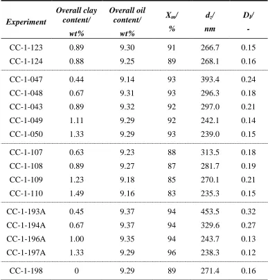
Table II-1. Overall clay and oil contents, final monomer conversions Xm, hydrodynamic diameters dz and dispersity indices DI of the different clay-stabilised poly(vinyl laurate) latexes prepared in miniemulsion polymerisation. ...32
Table III-1. Overall silica and oil contents, hydrodynamic diametersdzand dispersity indices DI of the different Ludox-stabilised polystyrene latexes prepared in miniemulsion polymerisation (pH ~3)...56
Table III-2. Overall silica and oil contents, hydrodynamic diametersdzand dispersity indices DI of the different Ludox-stabilised poly(styrene-co-vinyl pyridine) latexes prepared in miniemulsion polymerisation (pH ~10). ...57
Table III-3. Overall silica and oil contents, final monomer conversion Xm, particle size range dz from SEM imaging of a Ludox-stabilised poly(vinyl acetate) latex prepared in suspension polymerisation. (See Figure III-17 for SEM images in ‘Results and discussion’ section III.3.6) ...58
Table III-4. Stability of oil-in-water emulsions formed by hand-shacking mixtures of about 1 mL monomer (oil) in 10 mL of water containingca.0.5 mL of Ludox TM-40 colloidal silica sol at different values of pH (= stable emulsion, ~ = limited coalescence and,= coalescence). ...61
Table III-5. Gel formation of a dispersion of Ludox TM-40 colloidal silica (20 wt%) over time and at different pH (adjusted with addition of HCl)...63
Table III-6. Series of Ludox-stabilised polystyrene latexes prepared in miniemulsion polymerisation. dpart are the average diameters of Ludox silica nanoparticles (from SEM micrograph analyses). dz (DLS) and d (SEM) are the average diameters of the armoured latex particles measured by dynamic light scattering and from analysis of SEM micrographs (with the standard deviations), respectively. ...68
Table III-7. Analysis of the packing patterns of the silica nanoparticles on the surface of the polystyrene particles. Average ratios of nanoparticles having 4, 5, 6 or 7 neighbours, with their standard deviation, are reported for each batch, 1 (cc-1-114) and 2 (cc-1-199), and the average over the two batches. ....76
Table III-8. Composition of highly stable o/w emulsions of styrene, vinyl laurate or VEOVA-10 monomers using Ludox TM-40 (pH ~3) as solid stabiliser and an Ultra-Turrax T25 (24,000 rpm) to blend the mixtures. ...78
Table III-9. Composition of Ludox(TM-40) stabilised o/w emulsions of styrene monomer subsequently prepared by blending and ultra-sonicating the mixture (after the sonication process part of the monomer demixed and was not taken into account into those contents). ...80
Ludox(TM-40) stabilised poly(vinyl acetate) latexes prepared by emulsion polymerisation. Reactions conducted with various solids contents at pH ~4.5 and 65 ºC...95
Table IV-3. Composition (overall weight contents and weight ratios) of the Ludox(TM-40) stabilised poly(vinyl acetate) latexes prepared by emulsion polymerisation. Reactions conducted with various silica-to-monomer ratios at pH ~4.5 and 65 ºC...95
Table IV-4. Ludox(TM-40)-stabilised poly(vinyl acetate) latexes prepared by emulsion polymerisation at 65 ºC in a semi-batch process by feeding vinyl acetate until coagulation occurred (see text, section IV.3.4.1). ...96
Table IV-5. Composition (overall weight contents and weight ratios) of the polymer latexes prepared by emulsion polymerisation in presence of Ludox(TM-40) silica nanoparticles. Reactions conducted with vinyl acetate (VAc) and vinyl pivalate (VPiv) monomers at pH ~4.5 and sampled for disc centrifuge measurements. ...96
Table IV-6. pH of the Ludox sol, average particle sizes dz and dispersity indices DI (DLS), pH and zeta potentials of Ludox(TM-40) stabilised PVAc latexes. ...99
Table IV-7. Composition (overall weight content and silica-to-monomer ratio) of Ludox(TM-40) stabilised PVAc latexes prepared by emulsion polymerisation. Reactions conducted at 65 ºC and pH ~4.5...101
Table IV-8. Recipes for the synthesis of Ludox TM-40 stabilised PVAc latexes prepared by emulsion polymerisation at 65 ºC and initial pH 4.0. By decreasing the ratio silica to monomer, larger particles with broader distributions were obtained in batch reactions...101
Table V-1. Composition (overall weight contents and weight ratios) of the solids-stabilised poly(vinyl esters) latexes prepared by emulsion polymerisation using Ludox TM-40 silica (ca. 24 nm in diameter) unless indicated. Main criterion, changed from one sample to another, is shown in bold. 127
Table V-2. Average particle sizes dz and dispersity indices DI (DTS nano) of the solids-stabilised poly(vinyl esters) latexes prepared by emulsion polymerisation using Ludox TM-40 silica (ca. 24 nm in diameter) in all cases excepted in exp. cc-3-410 where Ludox SM-30 (ca.7 nm in diameter) was used. 128
Table V-3. Sedimentation studies of silica-stabilised poly(vinyl acetate)
latexes at increased ionic strength and pH. 131
Table V-4. Glass transition temperatures (Tg) of the solids-stabilised
poly(vinyl esters) latexes measured by DSC at a standard heating rate of 10 ºC
min-1(second heating). 133
Table VI-1. Composition of mixtures of colloids used in preparation of
This work would have not been achieved without the precious discussions,
advice and collaboration with numerous people at the University of Warwick
and elsewhere.
I am fortunate to have had the opportunity to work within the Bon Polymer
Colloid group, part of the material cluster of the Department of Chemistry since
October 2006. First of all I am very grateful to my promoter Assoc. Prof. Stefan
Bon for giving me the chance to join his team, for his precious enthusiasm and
numerous ideas and also the opportunity to present my research and network
through internationally leading conferences/journals.
I also would like to address special thanks to my industrial supervisor Dr. habil.
Wolf-Dieter Hergeth at Wacker Chemie AG (Burghausen, Germany). This work
would not have happened without the developed scientific research proposal and
their industrial financial support. Thank you for your advice and guidance
during this project.
Special thanks go to all the past and present members of the Bon Polymer
Colloid group. Thank you Nadia and Nicole (our post-docs) for your precious
help and encouragements, Pat especially for your guidance when I started and
Roberto for your contribution in our collaborative work. Thank you all for
interesting discussions, fun times in the labs and coffee breaks - Pat, Rich,
Nadia, Roberto, Tom, Andy, Nick, Nicole, Adam, Rong, Attyah, Gabit, Yunhua,
Fortuna and Dr. Alessandro Troisi (Department of Chemistry), as well as Dr.
habil. Wolf-Dieter Hergeth, Barbara Hager and Dr. Reinhard Härzschel (Wacker
Chemie AG, Germany) for interesting discussions and their involvement in our
successful collaborative works.
I acknowledge Steve York, Dr. Richard Dobedoe, Jane Green and Ian Portman
for their training and help with electron microscopes (Department of Physics
and School of Biology), Birmingham Science city Innovative for some of the
equipment used in this research (Uses for Advanced Materials in the Modern
World (West Midlands Centre for Advanced Materials Project 2) with support
from Advantage West Midlands (AWM) and partly funded by the European
Regional Development Fund (ERDF)), and Dr. K. Kindlay (John Innes Centre),
and staff from Quorumtech, Gatan, and Zeiss Cambridge UK for assistance with
cryo-electron microscopy.
I also would like to thank everybody who has encouraged me all the way or at
some stages of the accomplishment of this work. You know how much your
presence and your support in those times have been important to me; I am really
grateful for those fortunate moments. Not mentioning again friendships within
the Bon group, I also would like to name mi Pepes Sole, Sarah and Haz, also
Agnieszka & Michal, Zsuzsa, Flo, Julien, Ofelia, Schumi, Vicky, Stacy, Gaidad,
Ale, Dave, Martin, Paul, Jen, Sarah, Lucie, Claire, Mike, Raj, Ant, Alex,
and/or whenever I managed to visit Belgium, Xa, Pit, Cathy, Alex & Ju, Ben,
Val, Marie, Leen and Oana.
Most importantly I would like to thank my family. I am especially grateful for
the continuous support from my Mummy and I also would like to thank
Papounet José, Boubou, Marraine & Tonton, mon frérot Oli & Maëlle, Bon
I hereby declare that this thesis consists of my own work, and that it has not
previously been submitted for any previous degree at any institution. Production
of powders via spray-drying and their application tests in tile adhesive formulations, presented in Chapter V, were carried out at Wacker Chemie AG
(Burghausen, Germany) in the Polymer Research division, research laboratories
of Dr. Wolf-Dieter Hergeth and Dr. Reinhard Härzschel. Tests of the reinforced
hybrid polymer foams as gas sensors in Chapter VI were carried out in
collaboration with Dr. James Covington in the School of Engineering of the
University of Warwick, and cryo-SEM analyses were performed with assistance
of Dr. K. Kindlay (John Innes Centre), and staff from Quorumtech, Gatan, and
Zeiss Cambridge UK.
Where other sources of information have been used, they have been
acknowledged and referenced.
We investigated different strategies for the preparation of armoured polymer
particles. Inorganic nanoparticles, such as clay platelets and Ludox colloidal
silica grades, were used as solids-stabilisers in processes such as miniemulsion,
suspension and/or emulsion polymerisations. These nanoparticles were either
assembled at liquid-liquid interfaces for the stabilisation of monomer droplets or
adsorbed onto solid surfaces in the case of poly(vinyl acetate) latex particles.
Colloidal assembly was promoted by modifying the pH and/or the ionic strength
of the dispersion medium, thereby tuning the surface properties of the
nanoparticles. When prepared in miniemulsion polymerisation, latexes with
controlled particle size distributions were obtained. Their diameter was dictated
by the amount of solids-stabiliser (Laponite clay) or by the dimensions of the
building blocks (Ludox colloidal silica).
We developed a versatile emulsion polymerisation process leading to
silica-armoured poly(vinyl acetate) particles and showed that quantitative disc
centrifugation analyses throughout the polymerisation process unravelled
mechanistic aspects of particle formation and growth. Stability of the armoured
particles was studied in dispersion and after spray-drying the hybrid dispersions.
The thickness of the silica shell on the polymer particles had an important role
in limiting polymer inter-diffusion upon film formation. The obtained powders
were tested as additives in cement-based formulations for tile adhesives.
However, desired performance characteristics were not obtained in comparison
mixture of colloids. ‘Large-soft’ particles of poly(vinyl laurate) reinforced by an
armouring layer of ‘small-hard’ nanoparticles of colloidal silica led to the
formation of highly porous open-cell foams. Upon addition of a third conducting
colloidal component, this newly designed material proved promising results as a
(FEG-)SEM (Field Emission Gun-) Scanning Electron Microscopy
AIBN 2,2′-azobis(2-methylpropionitrile
C-black Carbon black
CPS Disc Centrifuge Particle Sizing
DI Dispersity index (often called Polydispersity index)
DLS Dynamic Light Scattering
DSC Differential Scanning Calorimetry
dz Hydrodynamic Diameter
Exp. Experiment
FCC Face-centred cubic
HCP Hexagonal close-packed
KPS Potassium persulfate
NaSS Sodium styrene sulfonate
NMR Nuclear Magnetic Resonance
PS Poly(styrene)
PVAc Poly(vinyl acetate)
PVL Poly(vinyl laurate)
PVOH Poly(vinyl alcohol)
PVPiv Poly(vinyl pivalate)
SDS Sodium dodecyl sulfonate
TEM Transmission Electron Microscopy
V-65 2,2'-azobis(2,4-dimethyl valeronitrile)
VL Vinyl laurate
VPiv Vinyl pivalate
Tg Glass transition temperature
Chapter I.
General introduction
This chapter introduces the field of interface and colloid science. Key
colloidal properties and assembly mechanisms for the formation of
raspberry-like particles are described. This introduction is followed by the main objectives
of this thesis which are put into their industrial context and finally, the research
I.1. Interface and colloid science
1Interface and colloid science is a branch of physical chemistry studying heterogeneous systems composed of at least one dispersed phase (not soluble) in
a dispersion medium. Each of the constituting phases can be either at a state of
gas, liquid or solid. A colloid can be defined as a substance composed of a system of particles, which also can be referred to as colloids, with linear dimensions in the range of about 10−9 to 5 × 10⁻⁷ m dispersed in a continuous
medium. Nature provides us with numerous colloidal dispersions, such as
natural rubber latex extracted from rubber trees, or milk which is an emulsified
butter fat dispersion. Graham identified colloidal particles for the first time in
the 1860s and discussed the constitution and properties of matter.2-3 He described the presence of colloids between the liquid and crystalline states
which in the case of silicic acid gels depended on their hydration, solubility, and
concentration. Nowadays, colloid science plays a significant role in
technological developments including a wide range of industrial sectors such as
pharmaceuticals, biotechnology, nanotechnology, food industry, and building
industry.
Colloids can be classified in two categories: lyophilic colloids for solvent loving particles and lyophobic colloids for solvent hating particles. Lyophilic colloid sols are thermodynamically stable. However most colloidal dispersions
are lyophobic meaning that the energy associated with creating and maintaining
the large area of contact between dispersed particles and dispersion medium is
significant. Thermodynamically unstable, these lyophobic particles can only be
them from aggregating over long periods. In this case, the barrier to undergo
coagulation is kinetic and the system is called metastable. In this work, lyophobic systems are considered and our study concerns dispersions of liquids
in liquids and solids in liquids.
I.2. Stabilisation of lyophobic colloids
As a result of their individual thermal motion, also called random Brownian motion, dispersed particles can potentially collide. These inter-particle shocks combined with attraction forces, such as van der Waals interactions, lead to
aggregation of the colloids. If two spheres are at close proximity and in a
vacuum, the following expression approximates the attractive potential energy,
a V :
H a A Va
12
Equation I-1
Where a is the radius of the spheres, and H is their minimum distance of separation. A is the Hamaker constant, characteristic of the material of the particles at the microscopic molecular or atomic interactions, which is reduced
by the self-attraction of the medium in the case of a liquid dispersion.
Different mechanisms of stabilisation or destabilisation tend to prevent or
provoke coagulation of dispersed solid particles. The term flocculation generally
refers to a reversible aggregation process. Four main categories of colloidal
I.2.1. Electrically charged colloids
To overcome attraction forces, particles can be stabilised by possessing
surface charges. Covalently bound or adsorbed, these charges induce the
formation of an electrical double layer. Due to the requirement of electroneutrality, an identical but oppositely charged layer of ions, so-called
surface ions, and a diffuse layer of mobile ions will be generated with ions
present in the continuous phase. Some ions are strongly adsorbed onto the
(particle) surface and form an inner sub-layer which is called the Stern layer. The electric potential, Vr, inside the electric double layer is expressed by the following equation:
KH
VVr s exp Equation I-2
WhereVsis the surface electric potential, His the distance from the surface andKis the characteristic thickness of the diffuse layer, called theDebye length, which depends on the ionic strength of the medium. The hydrodynamic diameter
includes the thickness of this layer, meaning this is not an absolute measure of
the actual dimension of the colloid. This influences measurements when
determining particle size distributions by dynamic light scattering, see Appendix
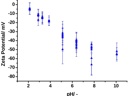
A, section A.3. The potential stability of electrically charged colloidal systems
can be evaluated by the magnitude of the zeta potential as measured by
electrophoretic light scattering, see Appendix A, section A.2.
Elaborated models to calculate the repulsive free energy between
electrically charged lyophobic particles have been developed. The “DLVO
between particles and the existence of the electrical double layer. When two
particles are brought together, due to their random thermal motion, known as
their Brownian motion, the cloud of their counter-ion layers will overlap. A higher ionic concentration between the particles than elsewhere leads to an
increase of the free energy of the system, either in terms of electrochemical
potential or osmotic pressure, which brings solvent from outside, both creating a
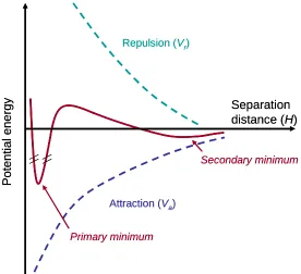
driving force for repulsion between the particles. The combination of the
electrostatic repulsion potential, to the van der Waals attraction and Born
repulsion potentials is represented in Figure I-1 as a function of distance from
the surface of a spherical particle. The primary minimum is generally so deep
that the energy to separate two particles from there is close to be infinite.
However, the presence of a secondary minimum in the resulting potential energy
Repulsion (Vr)
Attraction (Va)
Secondary minimum
Separation distance (H)
P o te n ti a l e n e rg y Primary minimum Repulsion (Vr)
Attraction (Va)
Secondary minimum
Separation distance (H)
[image:29.595.173.449.73.325.2]P o te n ti a l e n e rg y Primary minimum
Figure I-1. Schematic representation of the total potential energy (red line) obtained by adding the van der Waals attraction potential, Va, and the electrostatic and Born repulsion potentials,Vr, as a function of distance between two spherical particles. The height of the repulsive barrier indicates system stability.
I.2.2. Sterically stabilised colloids
Steric stabilisation, already described by Napper in the late 1960’s,9-13 is obtained by adsorption of non ionic macromolecules; typically, hydrophilic or
amphiphilic polymers are used and are referred to asprotective colloids.14 The particles interact only when their protective polymeric layers start overlapping.
The interpenetration of the polymer chains is called the compression region. The
main effects contributing to effective repulsion, or in other words to limited
compression, are the elastic and osmotic terms from the deformation and the
solvation effects of the polymeric chains, respectively. Commonly used in
anti-caking or suspending agent and often enhances the properties of a material when
film formed.
I.2.3. Depletion effect
The depletion effect involves the presence of free macromolecules (or
nanoparticles) controlling stabilisation or flocculation of uncharged dispersed
colloids. The polymer chains remain in the continuous liquid phase being inert
or repulsive to the polymeric surface or if all the adsorption-sites are occupied.
The attractive force between dispersed particles and free macromolecules having
no direct interactions between them was reported by Asakura and Osawa in
1958.18 They found that this force acts around the particles in the range of the diameter of the macromolecules and its magnitude is of the order of the osmotic
pressure of the solution of macromolecules. This stipulates that the average
segment density in free polymer is less near any surface than in the bulk phase.
Therefore, when approaching two polymer particles this engenders expulsion of
free macromolecules and creates regions of lower and higher concentrations of
free polymer. Flocculation is induced if the attraction and expulsion of the pure
solvent remaining between the particles occurs. This effect was studied for
common polymers such as poly(acrylic acid)19 and poly(methyl methacrylate) (PMMA).20 The bridging effect observed for the latest induced aggregation of the PMMA latex synthesised in emulsion polymerisation. The reason for this
was due to the presence of free polymer chain formed from predominant
nucleation in the aqueous phase as a result of high monomer water solubility. A
model of the interactions between uncharged macromolecules and micron
early 80s,21-22 argued that kinetic stabilisation can also result if the generated repulsion is strong enough. Lekkerkerkeret al.calculated this entropic depletion force, attractive or repulsive, between large spheres and avoiding smaller
particles23-24or rod-like macromolecules.25 I.2.4. Image charge effect
The feature of image charge effect is well known in classical electrostatics but is essentially described in theoretical work.26-31 Complex simulations calculate the interaction forces by considering charge density and the charge
distribution (dielectric constant) for polarisable matter. A simple description of
the image charge effect can be given as follows: when a charged particle is
brought close to a solid surface, the dielectric response of the medium leads to a
polarisation potential that counteracts the external charge. This material is
divided into point charges which are called the image charges.32 The resulting electrical force between the particle and the solid surface follows the Coulomb’s
law; that is to say that the magnitude between two point charges is proportional
to the magnitude of both electrical charges and inversely proportional to the
square of the distance separating the two points. The effective interaction of an
interface and an electrolyte, image charge effects plus the deformation of the
colloidal ion atmosphere by the interface, can be attractive or repulsive. Based
on the electrical double layer model, Klein and von Grünberg investigated the
consequences of a high accumulation of ion distributions next to charged objects
in electrolyte solutions, thereby modelling realistic examples such as the
like-charged planar wall, and somehow, it was experimentally demonstrated that a
precise measurement of these double-layer forces acting on a colloid near a
glass surface can be used to determine surface charge densities using total
internal reflection microscopy.33 Recently, Leunissen et al. conducted an interesting study on the electrostatic stabilisation effects of polymer colloids on
oil-water interfaces.34 Non-wetting particles but strongly bound to the oil-water interfaces were found to form surprisingly stable emulsions that can crystallise.
Based on electrostatic effects, the mechanism of haloing stabilisation is
described in section I.4.3.
I.3. Fabrication of supracolloidal structures
Based on the definition of supramolecular chemistry, which is the science
beyond the molecules, their interaction and assembly, supracolloidal chemistry refers to the assembly of colloidal components for the formation of complex
structures. Nanocomposites can be defined as materials having two or more phases and at least one of the constituent can be identified as colloid in the final
product.
Advanced colloidal assembly strives towards for mimicking natural systems
although the nano/microstruture of today’s most advanced composites has yet to
achieve the order and sophisticated hierarchy of hybrid materials built up by
living organisms in nature.35 Drug delivery systems36 or supports for tissue regeneration37 are only examples of important challenges for both colloid scientists and the healthcare industry in this case. Colloidal assembly has been
properties,39-41 electrical circuits,42 or materials of modulated tensile strength and ductile behaviours.43
Armeset al.recently published a review entitled:“Colloidal nanocomposite particles: quo vadis?” in which they focused on the increased interest in the development of polymer-silica latex particles over the last two decades.44 The termhybridcolloid is often used to define organic-inorganic colloidal systems; a broader definition also pertains to materials composed of at least two kinds of
incompatible organic polymers.45-46 One interesting morphological class of hybrid polymer latexes is those showing an armoured supracolloidal structure in
which inorganic nanoparticles are assembled onto and adhere to the surface of
the polymer latex spheres. These armoured hybrid morphologies when applied
to waterborne coatings feature for example scratch resistance,47-49 flame retardancy of the resulting films,50 or profound synergistic effects as an additive in waterborne pressure sensitive adhesives.51 Teixeira and Bon recently reviewed the different strategies for the preparation of hybrid nanocomposite
polymer latex particles.52 These colloidal interactions have been proven to be highly complicated. The next section relays key theories, models and types of
colloidal stability of interest for this work.
I.4. Interaction mechanisms for the preparation of
solids-stabilised latex particles
Ramsden was the first person, in 1903, to mention the presence of solids in
the surface-layers of solutions and suspensions and studied the separation of
of emulsions with insoluble emulsifiers.54 The term Pickering stabilisation, or Pickering emulsion, relates to his pioneering work and describes consequently
the directed assembly of colloidal particles onto emulsion droplets. Herein, three
types of system are distinguished: (i) the adherence of nanoparticles at
liquid-liquid interfaces for the stabilisation of liquid-liquid droplets, (ii) the adsorption of
nanoparticles on solid substrates such as larger polymer particles and (iii) finally
a brief description of the haloing phenomenon is given.
I.4.1. Particle wettability at liquid-liquid interfaces
An explanation for the phenomenon of Pickering stabilisation was given by
the theory of emulsification reported by Finkle et al. in 1923.55 This theory suggests that the particles are partially wettable by the two phases involved. In
1954, Wiley described that freshly prepared Pickering emulsions could undergo
limited coalescence before a stable set of solids-stabilised oil droplets in water
was obtained. Factors affecting the “limiting size” of the droplets in oil-in-water
emulsions were discussed.56
A 2-D model of the interactions of a monolayer of polystyrene spheres
trapped at a water/air interface was reported by Pieranski in 1980.57 The energy profile of a particle of radius R demonstrates why they can adhere to the interface. This model assumes a smooth and continuous liquid-liquid interface,
absence of gravity, a smooth surface of the spherical particle and negligible line
tension at the three phase contact line. A schematic representation is shown in
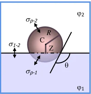
Figure I-2. Schematic representation of a solid spherical particle of radius R
sitting at the interface of φ1 and φ2 a distance Z from the centre C.
2 1 2
1, ,
p p are the surface/interfacial tensions between the particle and φ1,
the particle and φ2 and the two phases respectively and θ is the three-phase
contact angle.
The energies between the particle and the phase 1 (φ1), the particle and the
phase 2 (φ2) and between the two phases are reported in Equations (I-3) to (I-5)
respectively: ) 1 ( 2 . 2 1
1 R z
Ep p Equation I-3
z
REp2 p22 2 1 Equation I-4
2
2 2 1 2
1 R 1 z
E Equation I-5
Where z Z R is the dimensionless vertical coordinate measured from the
centre C, with respect to the level of the phase 1. p1,p2,12 are the
surface/interfacial tensions between the particle and φ1, the particle and φ2and
the two phases respectively.
The total energy,E, is the summation of the energies given in Equations
(I-3) to (I-5) and 1 2
2
R
Eunit is defined to scale the surface energies, so that the
energy E~ is written:
unit E E
E~ Equation I-6
Using Equation (I-7) and Equations (I-4) to (I-6), respectively, the following
quadratic function is found:
2 2 12
~ 2
b a z b a z
E Equation I-7
Where, ap2 12 and bp1 12
The parabola of this function depends on the values of interfacial tension
but in the case of successful adherence of the particle at the interface, the
minimum energy min ~
E will appear for values of z comprised between -1 and +1
[image:36.595.238.424.470.630.2]as represented in Figure I-3.
Figure I-3.Potential energy curvature of a solid particle leaving the interface to
go in φ1( 1
~
E ) or in φ2(E~2) where, zminis the vertical coordinate of the centreC,
position of the particle at the liquid-liquid interface, at minimal energy ( min ~ E ). 1
~
E
2~
E
1
z
z
Consequently, E~1 E~1E~min and E~2 E~2 E~min represent the
quantities of energy required to the particle to move in phase 1 and in phase 2
respectively.
Clint and Taylor found that the energy required to remove the particle from
the interface into phase 1 or 2 becomes independent from the surface tensions
between both liquids and the particle (P1,P2) by using the following
Young’s equation for equilibrium at the three-phase contact line:58
p2 p1 12 cos Equation I-8
Where is the three-phase contact angle describing the position at which
the particle sits at the interface.
The general expression of the energy is then expressed as:
22 1 2
cos
1
R
E Equation I-9
The sign in the brackets is negative for θ < 90 º, when the particle is
removed into the water and positive forθ > 90 º, when it is removed into the oil
phase. The radius R of a particle and the interfacial tension between the two
liquids 12 are generally known. Due to its simplicity this equation is often
used to calculate the energy with which a particle could be held at an
interface.59-61
Hence, solids particles are used as emulsifier and their effectiveness in
stabilising emulsion droplets, sometimes called Pickering emulsions, is tuned by
the surface properties of the particles and the nature of the liquid phases. Levine
repulsive interactions are negligible in comparison to the energy depth of a
single particle.62 They also concluded that in equilibrium partitioning virtually all the particles should be deposited on the emulsion droplets when enough
interface area is created. Recent advances using this strategy for the formation of
supracolloidal structures and the importance of line tension are described in
Chapter III.
I.4.2. Colloidal assembly by controlled heterocoagulation
Assembly of solids particles through heterocoagulation refers to their adsorption onto a surface which can result from several types of interactions.
Controlled adhesion of nanoparticles around larger particles is commonly
achieved through hydrogen bonding interactions or ionic bonds leading to stable
colloidal nanocomposites. The theory of heterocoagulation was developed by
Hogget al.who were the first to present, in 1966, a quantitative theory derived from the diffuse double layer theory. They described the kinetics of coagulation
of different hypothetical colloidal species under various conditions such as the
concentration of potential-determining ions, the total concentration of ionic
species in the supporting electrolyte, the particle size and the relative
proportions (in terms of numbers of particles) of the two solid components.63In 1976, Schott experimentally investigated the flocculation of a suspension
constituted of positively and negatively charged colloids and attributed this
phenomenon to a heterocoagulation process, i.e. charge neutralisation of bismuth subnitrate by bentonite (clay).64A common approach consists of adding a co-monomer for the synthesis of the polymer beads for the formation of
deposition of cationic polystyrene latex prepared by using N,N-dimethylaminoethyl methacrylate as co-monomer on polyacrylonitrile,
polyamide, and polyester fibres as a function of pH.65 Many systems have been reported over the last few years using similar strategies and are developed in
Chapter IV.
I.4.3. Haloing stabilisation
Lewis et al. reported in 2001 a new stabilisation mechanism for which the presence of a critical volume of highly charged nanoparticles (hydrous zirconia)
would enhance the stabilisation of microspheres negligibly charged (silica).66 The nanoparticles were arranged in halos around the microspheres. This was
supported by zeta potential analysis showing an effective charge build-up of the
microspheres. However they observed by scanning angle reflectometry that
nanoparticles did not adsorb on the surface of the microspheres. This
mechanism was then investigated by means of direct simulation which showed
that haloing stabilisation occurs over a window of nanoparticle concentrations
and also sensitively depends on nanoparticle charge and colloid-nanoparticle
size asymmetry.67-69
Direct force measurements between a silica sphere attached to the cantilever
of an atomic force microscope and a silica flat surface demonstrated with
increasing concentration in zirconia nanoparticles a transition from an attractive
to a repulsive forceviaa meta-stable peak observed in the presence of different concentration in zirconia nanoparticles.70Another example involving aluminium oxide microspheres stabilised by highly charged cerium oxide was described
by Karimian and Babaluo.71 Rheological properties, colloidal stability, and 3-D structure of assembled colloids through this mechanism have been highlighted
by Rhodes and Lewis.72 They showed that halo-stabilised suspensions exhibit Newtonian flow behaviour whereas an increase in the apparent viscosity and
degree of shear thinning was observed for the flocculated suspension, at lower
or higher concentration in stabilising nanoparticles.
I.5. Objectives and outline of the thesis
In this thesis, the formation of supracolloidal structures is explored using
interface-driven assemblies as a strategy to form armoured composites.
Inorganic and polymer colloids in the range of nanometers to micrometers are
used as building blocks. Several routes for the synthesis of polymer particles
armoured with inorganic nanoparticles are developed and we also investigate the
arrangement and packing of those nanoparticles on the polymeric spheres and
their tendency in prohibiting film formation of the polymer particles.
The industrial goal of this project, agreed with Wacker Chemie AG, is to
investigate and design the use of nanoparticles as solid stabilisers for the
synthesis of poly(vinyl esters) latexes. The final product should ideally be in the
format of redispersible powders. The application lying behind the development
of those armoured latexes/redispersible powders is to be utilised as additives in
cementitious applications. Polymer modified dry mix mortars, or one pack
systems, are of great importance for the construction industry. Conventionally
poly(vinyl alcohol) is used as protective colloid for the synthesis of poly(vinyl
acetate) based latexes, and is added to the latexes during spray-drying to prevent
Silica particles show direct compatibility in the formulation as cement is
notably composed of clay, sand and calcium silicates. Therefore, our purpose is
to investigate different types of silica nanoparticles for the stabilisation of
polymer particles prepared via several polymerisation processes such as miniemulsion, suspension and emulsion polymerisation. Particle behaviour and
stabilisation mechanisms are studied for better understanding and to be able to
target a solids-stabilised system with no addition of any co-monomer, surfactant
or macromolecules which usually increase the cost of production.
In spite the hydrophilicity of vinyl acetate and its tendency to hydrolyse, the
composition of the armoured latex should have the highest possible ratio
poly(vinyl acetate)/poly(vinyl neodecanoate-based). Criteria such as pH and
composition need to be addressed to optimise the solids-stabilised
polymerisation process to specifics for industrial applications. Solids content of
the latexes should be increased as much as possible, reaching typically above 50
wt%. Mechanistic and kinetic aspects of the process have to be studied and
optimised to tune the particle size distribution. Currently, latexes in the size
range of 800 nm – 5 micron in diameter are used commercially. Colloidal
stability of the prepared latexes has to be achieved at high value of pH and high
ionic strength to mimic the chemistry in cement applications, i.e. pH 12 with high concentration in calcium cations. Film formation of the scaffolded
solids-stabilised dispersions should be prevented during spray-drying and the powders
could be tested in cementitious applications to conduct a comparative study to
We present here a brief overview of each chapter:
Chapter II extends the use of Laponite clay discs as solid stabiliser in
Pickering miniemulsion polymerisation. Previous work on armoured latex
particles of polystyrene and various hydrophobic (meth)acrylates were made
upon solidification by polymerisation of the monomer droplets stabilised with
Laponite clay platelets and particle size distribution was controlled by the
amount of stabilisers. In our case, special consideration was given to the
synthesis of clay – poly(vinyl esters) latexes, specifically using vinyl acetate and
vinyl laurate. Limitations and drawbacks in preparing poly(vinyl esters) latexes
in a miniemulsion process and using clay platelets as solid-stabilisers are
addressed.
Chapter III focuses on the assembly of silica nanoparticles at liquid-liquid
interfaces for the synthesis of oil-in-water or water-in-oil emulsions. We
developed this strategy to prepare armoured polymer latexes of micron- and
submicron-sizes using free radical suspension and miniemulsion polymerisation
processes and investigated the preparation of high solids content hybrid polymer
latexes. Dimensions of the building blocks were found to have an influence on
the average particle size of the prepared latexes and we also studied their
packing patterns on the latex particles.
Chapter IV is dedicated to the development of a versatile emulsion
polymerisation process in which solid nanoparticles are used as stabiliser for the
simple fabrication of armoured nanocomposite of poly(vinyl acetate) latexes.
Key mechanistic events of solids-stabilised emulsion polymerisations are
tool to determine the fate of nanoparticles in their use as solids-stabilisers.
Chapter V covers the investigation of the role of the silica nanoparticles
armouring the polymer latexes. By increasing the pH better colloidal stability
was obtained until coalescence occurred at high ionic strength. In the
spray-drying process the thickness of the silica shell had an important role in limiting
polymer inter-diffusion upon film formation. A series of powder coatings made
through spray-drying of the armoured polymer latexes were tested as additives
in cement-based formulations for tile adhesives. Desired performance
charactersistics, however, were not obtained in comparison to standard
formulations.
Chapter VI describes the fabrication of nanocomposite reinforced soft
polymer foams, which were built by freeze-drying a mixture of colloids
dispersed in water, thereby using ice-crystals as template for the porous
structure. “Soft” polymer latex particles film-formed and the cell walls were
covered by “hard” nanoparticles which maintained the foam structure by
enhancing its robustness. Addition of carbon black as a third colloidal
component led to conducting nanocomposite foams which could be used as
promising gas sensors.
The main conclusions and the industrial outlook of this thesis are
I.6. References
1. Hunter, R. J., Foundations of colloid science. 2nd Ed. ed.; Oxford University Press Inc.: 2001.
2. Graham, T.,J. Chem. Soc., Trans.1864,17, 368-371. 3. Graham, T.,J. Chem. Soc., Trans.1864,17, 318-327.
4. Deryagin, B.; Landau, L.,Acta Physicochim. URS1941,14, 633-62. 5. Verwey, E. J. W.; Overbeek, J. T. G., Theory of the Stability of Lyophobic Colloids. Elsvier Pub. Co.: 1948; p 216.
6. Overbeek, J. T. G.,J. Colloid Interf. Sci.1977,58(2), 408-422. 7. Bleininger, A. V.,Tran. Am. Ceram. Soc.1911,12, 504-16;3. 8. Oden, S.,Z. Physik. Chem.1912,78, 682-707.
9. Napper, D. H.,J. Colloid Interf. Sci.1969,29(1), 168-70. 10. Napper, D. H.,J. Colloid Interf. Sci.1970,33(3), 385-93. 11. Napper, D. H.,J. Colloid Interf. Sci.1970,32(1), 106-14. 12. Napper, D. H.,J. Colloid Interf. Sci.1977,58(2), 390-407.
13. Napper, D. H.; Netschey, A.,J. Colloid Interf. Sci.1971,37(3), 528-35. 14. Fitch, R. M., Polymer Colloids: A Comprehensive Introduction. Academic Press Limited: 1997; p 364.
15. Walker, I. F. U.S. Patent 2519088, 1950.
16. Wesslau, H.; Wilhelm, H.; Wolf, H.; Faulhaber, G. DE. Patent 62-70057 1244409, 1967.
17. Whiteley, T. E.; Perry, E. J. FR Patent 1444543, 1966.
18. Asakura, S.; Oosawa, F.,J. Polym. Sci.1958,33(126), 183-192.
19. Liang, W.; Tadros, T. F.; Luckham, P. F.,Langmuir1994,10(2), 441-6. 20. Chu, H.-H.; Hsu, X.-C.,J. Appl. Polym. Sci.1994,51(9), 1653-1658. 21. Feigin, R. I.; Napper, D. H.,J. Colloid Interf. Sci.1980,74(2), 567-571. 22. Feigin, R. I.; Napper, D. H.,J. Colloid Interf. Sci.1980,75(2), 525-541. 23. Lekkerkerker, H. N. W.; Widom, B., Physica A 2000, 285 (3-4), 483-492.
24. Mao, Y.; Cates, M. E.; Lekkerkerker, H. N. W.,Physica A1995,222 (1-4), 10-24.
25. Mao, Y.; Cates, M. E.; Lekkerkerker, H. N. W., Phys. Rev. Lett. 1995,
75, 4548.
26. Winter, H.,J. Phys. Condens. Matter1996,8(49), 10149-10183. 27. Hatlo, M. M.; Lue, L.,Soft Matter2008,4(8), 1582-1596.
1705-1719.
29. Banchio, A. J.; Gapinski, J.; Patkowski, A.; Häußler, W.; Fluerasu, A.; Sacanna, S.; Holmqvist, P.; Meier, G.; Lettinga, M. P.; Nägele, G., Phys. Rev. Lett.2006,96, 138303.
30. Denton, A. R.,Phys. Rev. E2007,76(5-1), 051401/1-051401/11.
31. Denton, A. R., J. Phys. Condens. Matter 2008, 20 (49), 494230/1-494230/8.
32. Jackson, J. D., Classical Electrodynamics. Third ed.; John Wiley & Sons, Inc.: 1999.
33. von Grunberg, H. H.; Helden, L.; Leiderer, P.; Bechinger, C., J. Chem. Phys.2001,114(22), 10094-10104.
34. Leunissen, M. E.; van Blaaderen, A.; Hollingsworth, A. D.; Sullivan, M. T.; Chaikin, P. M.,P. Natl. Acad. Sci. U.S.A.2007,104(8), 2585-2590.
35. Wei, W.; Yang, Z.,Adv. Mater.2008,20(15), 2965-2969.
36. Duran, J. D. G.; Arias, J. L.; Gallardo, V.; Delgado, A. V.,J. Pharm. Sci.
2008,97(8), 2948-2983.
37. Freemont, T. J.; Saunders, B. R.,Soft Matter2008,4(5), 919-924. 38. Stebe, K. J.; Lewandowski, E.; Ghosh, M., Science 2009, 325 (5937), 159-160.
39. Pileni, M. P.,Cryst. Res. Technol.1998,33(7-8), 1155-1186.
40. Yodh, A. G.; Zimmerli, G.Entropically driven self-assembly of colloidal crystals on templates in space; University of Pennsylvania, Philadelphia, PA, U.S.: 2002; 1-16.
41. van Dillen, T.; van Blaaderen, A.; Polman, A.,Mater. Today2004,7 (7-8), 40-46.
42. Velev, P. O. D., Assembly of Electrically Functional Microstructures from Colloidal Particles. In Colloids and Colloid Assemblies, Prof. Frank, C., Ed. Wiley-VCH: 2004; 437-464.
43. Bonderer, L. J.; Studart, A. R.; Gauckler, L. J., Science 2008, 319 (5866), 1069-1073.
44. Balmer, J. A.; Schmid, A.; Armes, S. P.,J. Mater. Chem.2008,18(47), 5722-5730.
45. Guyot, A.; Landfester, K.; Joseph Schork, F.; Wang, C., Prog. Polym. Sci.2007,32(12), 1439-1461.
46. Alexandre, M.; Dubois, P.,Mater. Sci. Eng.2000,28(1-2), 1-63. 47. Xue, Z.; Wiese, H. US Patent 7094830, 2003.
48. Bauer, F.; Flyunt, R.; Czihal, K.; Buchmeiser, M. R.; Langguth, H.; Mehnert, R.,Macromol. Mater. Eng.2006,291(5), 493-498.
![Figure II-2. Monomer conversion followed by 1H NMR spectroscopy in thepresence of a water soluble scavenger ([], CC-1-124) and without ([ ], CC-1-123).](https://thumb-us.123doks.com/thumbv2/123dok_us/9707383.471869/61.595.164.434.92.297/figure-monomer-conversion-followed-spectroscopy-thepresence-soluble-scavenger.webp)
![Figure II-3. Graph of the hydrodynamic average diameter dz of the clay-stabilised poly(vinyl laurate) latexes versus the overall amount of clay platelets[] (and calculated values from the fitted model [▲], see Figure II-4).](https://thumb-us.123doks.com/thumbv2/123dok_us/9707383.471869/63.595.165.438.84.296/figure-hydrodynamic-diameter-stabilised-laurate-platelets-calculated-figure.webp)