Abstract— In this study, a deep analysis of the reliability of lead-free (SnAgCu) solders in comparison with tin-lead solders have been done for a particular aerospace application. Creep properties of this solder composition have been investigated, and results have been validated with a thermal shock test. An 0805 resistor has been considered to simulate creep deformation, an electronic board has been used for a thermal shock test to check continuity of the circuit for the specified mission, and finally a detailed metallographic study has been performed. Main constitutive relations have been implemented in a commercial finite-element analysis software (ABAQUS 6.5), to predict creep strain accumulation under thermal loads. Effects of implementing different constitutive relations in compare with life prediction models have been investigated. Overall, both solders are highly reliable with this number of thermal cycles; however, SnAgCu shows higher life time under this type of loading.
Index Terms—lead-free solder, finite-element analysis, creep deformations, reliability analysis.
I. INTRODUCTION
Soldering is the most practical joining method that uses low-melting-point alloys, the solder, to join the electrical packages to the substrate, electrical board. In the huge electronic applications, solder is an irreplaceable material in the assembly process; as a joining material, solder provides electrical, thermal and mechanical continuity in electronic assemblies. The quality of soldering and the solder are two crucial elements of the integrity of a solder joint, which is vital to the overall functioning of the assembly by itself. Forming mechanical bonds, the shrinking interconnects size brings solder joint reliability to the forefront.
Considering different operating conditions, the solder joints could experience various kinds of loading; this includes overstress, thermal cycling, vibration and shock, and cycle bending of circuit boards. As a result of every loading condition the solder may plastify, creep or rupture, the first two are considered as the principal deformation mechanisms in the solder joints. The effect of each one is determined according to the operating condition, for example where the solder does not experience too much stress the role of creep is more important rather than plasticity. This especially happens when the package goes through a thermal cycle not a mechanical cycle like bending or shock, and the operating
Manuscript received July 30, 2008.
A. M. Lajimi, MSc, is with the Department of Mechanical Engineering, Laboratory of Applied Mechanics and Reliability analysis, Ecole Polytechniqe Federale de Lausanne (EPFL), CH-1015 Lausanne, Switzerland, Tel:+41 21 6933889, [email protected]
Dr. J. Cugnoni, is with the Department of Mechanical Engineering, Laboratory of Applied Mechanics and Reliability analysis, Ecole Polytechniqe Federale de Lausanne (EPFL), CH-1015 Lausanne, Switzerland.
Porf. J. Botsis is with the Department of Mechanical Engineering, Laboratory of Applied Mechanics and Reliability analysis, Ecole Polytechniqe Federale de Lausanne (EPFL), CH-1015 Lausanne, Switzerland.
temperature is around or bigger than half of the melting temperature in absolute scale.
Solder interconnects are used to provide:
• Electrical connection between package and the substrate.
• Mechanical binding between package and substrate. • Heat diffusion from the package.
Because the coefficient of thermal expansion (CTE) are different between the package, ceramic or polymer, and substrate, tensile and/or shear strains occur in the solder interconnects when the device is powered on and heat is generated. If the device is powered on and off, or the temperature of the environment fluctuates periodically, such heat induced tensile/shear strain within interconnects is as a result cyclic – causing thermo-mechanical fatigue failure.
Darveaux and Banerji 1992 [1] , and Darveeaux et al. 1995 [2], have done a significant amount of tests on actual soldered assemblies to properly account for the effects of grain and inter-metallic compound distribution. Pao et al. 1994 [3] performed thermal cyclic shear/strain test and determined hysteresis response of 63Sn-37Pb solder joints using a double beam specimen. Nurmi et al. 2004 [4] performed thermal shock tests on two types of resistors, 0603 and 0405, for different solder compositions for a -40 C to +125 C cycle. Pang et al. 2005 [5] performed constant load tests at different temperature with constant load set for several different stress levels. Spraul et al. 2007 [6], performed some tests on low temperature confired ceramics (LTCC)1 substrates to study
the lifetime of flip-chip solder joints for this type of substrate. Xie and Xie 2007[6], examined reliability of LF assemblies under thermal cycling (0-100) for different types of surface finishes.
In the present study, Finite Element Analysis (FEA) has been performed to simulate creep deformation according to a suitable constitutive relation, and then the result of this simulation has been used; accumulated creep strain during one cycle, to predict the number of life cycle to failure using a life-prediction relation. Moreover, a thermal shock experiment has been designed to evaluate the reliability of both SnPb and SnAgCu for a pre-determined number of cycles, then solder joints have been studied using metallographiy and optical microscopy and.
II. FINITE ELEMENT MODELING
Modeling is a useful tool used to supplement or replace accelerated tests, particularly in the early design states. The modeling discussed here applies to creep induced ductile fracture only, and so will be suitable for modeling the damage that occurs due to typical thermal cycling of solder joints. The constitutive law plus fatigue law class of methods (encompassing FEM) are very popular, providing more accurate predictions with fewer restrictions than analytical methods, however, with increased set up time and computational cost [7].
For modeling creep deformation considering it as the most important damage mechanism influencing solder reliability due to thermal cycling loads, one of the frequently used packages has been chosen. This simulation is carried out in two dimensions thanks to the symmetry of the component and uniform cross-section through the thickness of the package. Geometry of the model is presented in Fig. 1, the dimension of the land pattern for an 0805 resistor and the thickness of the solder is taken from [8].
A. Material Properties
FR-4, package, and copper-layer are considered elastic materials just with elastic time-independent properties, and solder is the only material with time –dependent properties. Package is supposed to be made of alumina (Al2O3), and
copper-layer’s properties will be the extracted from [9], Table 1. Solder is considered as an inelastic material with time and temperature dependent behavior, however only creep is considered as the main deformation mechanism. At first it is desired to have value or relation for elastic modulus of both solders; SnPb and SnAgCu.
In different references there are different values and relations for calculating elastic modules. For SnAgCu, values or relations of elastic modulus from each reference are implemented with the corresponding constitutive relation; secondly, an average value of elastic modulus and a new constitutive equation which is obtained by fitting to other equations are employed. For SnPb the same approach is followed, but the most conservative result is taken into account for final comparison.
Mathematically, steady state creep is described either by a Dorn type or sinh equation, and number of life cycles to failure is related to the accumulated creep strain by a “Coffin-Manson” type relation proposed by Shubert et al. [10] and Syed [11].
To proceed further a comparison of the constitutive equation for SnAgCu is done by plotting creep strain rate evolution versus stress in the average temperature. All available constitutive relations [4, 10, 12, 13, 14, 15, 16] have been transformed to the tensile form using (1) and (2) [17], results are plotted for different stresses at 283.15 K, Fig.3.
Where and represent the stress, shear stress in MPa, and and represent the strain and shear strain.
As it is clear in the Fig. 2 some creep relations have been developed either for low stress or for high stress region. It is desired to have the safest assumption for predicting number of life cycles to failure; it means creep strain should reach to a high value. Neglecting laws with limited application, a relation is fitted to upper bound of the constitutive curves. The procedure of choosing a suitable relation includes calculating reasonable activation energy, which is obtained by averaging selected constitutive relations is presented in Table 2.
B. New Sinh Relation
By fitting a new equation to the selected constitutive relations, a new sinh is presented, (3), the corresponding plot is presented in the Fig. 3.
This new constitutive relation would predict a higher accumulated creep strain which would result in a safer prediction in terms of life time. In terms of elastic modulus, an average curve of different values from different resources [4, 5, 10, 12, 14, 15, 16, 18] has been considered, (4).
[image:2.595.308.555.206.429.2]For SnPb same procedure was followed and safe assumptions were considered either in terms of constitutive relation and other material properties.
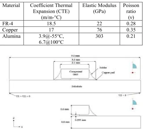
Table 1. Material properties for 2D FE-analysis. Material Coefficient Thermal
Expansion (CTE) (m/m-°C)
Elastic Modulus
(GPa) Poisson ratio
(ν)
FR-4 18.5 22 0.28
Copper 17 76 0.35
Alumina 3.9@-55°C,
[image:2.595.326.561.465.634.2]6.7@100°C 303 0.21
Fig. 1. 2D model of 0805 resistor, copper pad's thickness,0.035 mm.
Fig. 2. Creep strain rate is plotted versus equivelant stress for SnAgCu at T= 283.15 K for different constitutive relations
Table 2. Activation energy for SnAgCu. Relation Schubert NIST Pang Lau New Activation
energy
Fig. 3. New constitutive relation in compare to other selected constitutive relations.
Table 3. Elastic modules for SnAgCu. Elastic Modules (MPa)
Temp.(K) 223.15 348.15
Osterman 50597.14 50592.14
Zhang 24219.4 24216.83
Vandevelde 62052.5 37921.25
Kariya 51763.65 38138.65
Lau 53004 52994
Schubert 56909.65 39197.15
C. Boundary Conditions and Loads
A preliminary finite element analysis has been performed to determine boundary conditions for creep analysis. During first stage, real boundary conditions in the space such as orbital situation and heat generation by electrical packages were modeled to determine temperature variation function throughout the board.
As a result, a sin function was observed to give a good approximation of temperature variation on the board with a minimum equal to -55°C and a max of +75°C. This function could be applied as a uniform field temperature in FE-analysis of creep considering negligible heat generation in 0805 resistors. Stability of this temperature function after a large number of cycles was verified as well. A cross section of the whole assembly and a part of the PCB which corresponds to the designed experiment has been modeled, and it has been assumed that there are two displacement boundary conditions on two lower corners of the PCB, Fig. 1.
III. RESULTS A. 2D FE- Analysis
Solder joints are often causing of failure in electronic devices, failure due to cyclic creep induced ductile fatigue. In the following, the results of 2-dimensional creep modeling of a cross-section of solder joints under thermal cycling conditions, nominal and accelerated, in order to predict life time have been considered. Temperature is applied using a sin function as a uniform field on the whole model. This temperature function is periodic as a result of environmental conditions; a short period for test cycles (20 min) and a large period (90 min) corresponding to thermal shock test and real conditions are used.
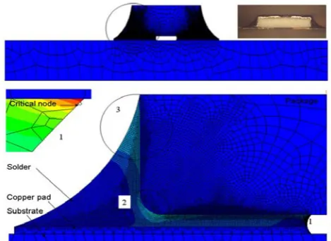
There are different approaches for calculating life time,
considering application the safest method could be described as finding a node where maximum accumulated creep strain (ACS) is induced, then correlate this value with number of life cycles to failure, Fig. 4.
A second step could be considered as determining the minimum number of cycle required for creep analysis. An initial analysis has been performed for five real cycles using material properties of SnAgCu and SnPb. After one cycle there is a constant increase in accumulated creep strain, Fig. 5. As a result, for further analysis three test cycles and two real cycles are simulated, and accumulated creep strain in the critical node in order to predicting life time is extracted.
For SnAgCu, the stresses reach much higher values during the temperature cycling, resulting in higher hysteresis loops. Although the creep strain for SnAgCu during test is smaller, the dissipated energy per cycle is higher due to the higher stresses. Fig. 6 shows the hysteresis loops for one normal and one shear stress/strain component and proves the upper statement.
A comparison between results of implementing different constitutive relations and different life prediction models showed, Fig. 7.
1. Shubert’s life prediction model gives more conservative results in compare with Syed’s relation,
2. Constitutive relations influence final results greater than life prediction models.
For new SnAgCu constitutive relation and Pao’s SnPb constitutive relation, the numbers of life cycles to failure, for other critical regions, Fig 4 were calculated to see the risk of first calculation and the probability of crack propagation through the solder joints under the component or through the solder toward its fillet edge. This was done for real cycles using Scubert’s prediction model which seems more critical. The results of this calculation are presented in Table 4 this proves how much first calculations were safe and conservative, and it is not expected to see any damage for one thousand test cycles of complete satellite preliminary mission, in addition to that effects of higher and lower stress regions on induced ACS and importance of constitutive relations are shown, for example in low stress regions SnAgCu gives lower ACS and higher life time.
2D FEA creep shows both solders would last more than 1500 cycles (~3 months), considering the worst case. In addition to that, simulations suggest that cracks will start more likely under package.
[image:3.595.317.552.581.752.2]Fig. 5. Accumulated creep strain for five real cycles, first cycle is critical and creep accumulates faster.
Fig. 6. Stress strain hystersis loop for real cycles during 6th cycle, for SnAgCu in compare to SnPb for one normal and one shear
[image:4.595.314.547.284.459.2]component of the stress and strain.
Fig. 7. Effect of different constitutive relations in compare with different life prediction model.
Table 4. Number of cycles to failure for three critical regions of solder joints in 2D simulation using Schubert's relation for life
prediction.
Node 1 2 3
SnAgCu 1702 11255 15770
SnPb 1460 6157 11691
B. Microstructural Analysis
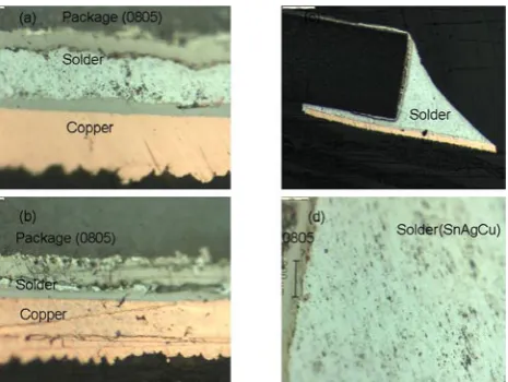
For microstructural analysis a metallographic process proposed by EMPA (A material science and technology research institution of the Swiss Federal Institute of Technology), was followed firstly, to analyze solder joints. Two groups of picture were taken, first group were taken after polishing and before etching, and second group were taken after etching process, then comparing the pictures resulted in keeping the pictures without etching, Fig. 7 and Fig. 8.
[image:4.595.57.296.478.639.2]There is no damage around the package, moreover microstructure seems fine and no damage or crack is observed. However, under the package solder layer is very thin, generally less than what is observed here. In a few cases where there are enough solder, no major damage is observed. Microvoids have been formed in the solder especially under the package.
Fig. 8. Microstructure of solder joints after 1000 cycles thermal shock test for SnAgCu, no major deformation observed.
Fig. 9. Microstructure of solder joints after 1000 cycles of thermal shock test for SnPb, some big cracks have been developed under
[image:4.595.314.555.514.691.2]V. CONCLUSIONS
Deformations of solder joints under thermal loads have been simulated. Creep plays the most important role where solder joints are thermally loaded. To simulate creep deformation of lead-free solders a new constitutive relation has been fitted to all adequate available constitutive relations to have the worst case in terms of creep accumulation. Taking into account temperature variation from first analysis, creep deformation has been determined using a finite-element software (ABAQUS 6.5), in 2-dimension for a small package, 0805 resistor.
Results show that both SnPb and SnAgCu would withstand this type of loading for a long number of life cycles, and safe enough to be used up to 2000 cycles at least. All major constitutive relations have been implemented to the finite-element analysis. It has been shown in 2-dimensional analysis, that solder does not experience so much stress. This could justify why SnAgCu shows a higher life time.
It is recommended to use SnAgCu, since solders are thermally loaded rather than mechanically and stress level is generally low, except in a few locations under the package close to the edge where the risk of total failure of package is not high.
VI. ACKNOWLEDGEMENT
Authors would like to thank Mr. G. Rothlisberger and Mr. F. Jordan at Space Center of EPFL, for their help in preparing and performing thermal shock test.
REFERENCES
[1] R. Darveaux and K. Banerji. (1992). Constitutive relations for tin-based solder joints. IEEE Transactions on components, Hybrids
and Manufacturing Technology. 15, No.6.
[2] R. Darveaux, K. Banerji, A. Mawer and G. Dody. (1995). Reliability of
Plastic Ball Grid Array Assemblies. Ball Grid Array Technology,
McGraw-Hill.
[3] Y.H. Pao, S. Badgley, R. Govila and E. Jih. (1994). Experimental and Modeling Study of Thermal Cyclic Behavior of Sn-Cu and Sn-Pb Solder Joints. Material Research Society Symposium Proceeding. 323,
pp.153-158.
[4] Q. Zhang, A. Dasgupta and P. Haswell. (2003). Viscoplastic Constitutive Properties and Energy-Partitioning Model of Lead-Free Sn3.9Ag0.6Cu Solder Alloy. Electronic Components and Technology
Conference, IEEE.
[5] J. H. L. Pang and B. S. Xiong. (2005). Mechanical Properties for 95.5Sn3.8Ag0.7Cu Lead-free Solder Alloy. IEEE Transactions on
components and packaging Technologies.
[6] M. Spraul, W. Nuchter, A. Moller, B. Wunderle and B. Michel. (2007). Reliability of SnPb and Pb-free Flips Under Different Test Conditions.
Microelectronics Reliability.47, pp.252-258.
[7] S. Ridout and C. Bailey. (2006). Review of Methods to Predict Solder Joint Reliability Under Thermo-Mechanical Cycling. Fatigue Engng
Mater Struct.30, pp.400-412.
[8] IPC-SM-782, Surface Mount Design and Land Pattern Standards, Section 8, 93.
[9] http://www.matweb.com . Accessed on July 15, 2008.
[10] A. Schubert, R. Dudek, E. Auerswald, A. Gollhardt, B. Michel and H. Reicbl. (2003). Fatigue Life Models for SnAgCu and SnPb Solder Joints Evaluated by Experiments and Simulation, Electronic
Components and Technology Conference. IEEE.
[11] A. R. Syed. (2004). Accumulated Creep Strain and Energy Density Based Thermal Fatigue Life Prediction Models for SnAgCu Solder Joints. ECTC Conference Proceeding, pp.737-746.
[12] M. Osterman and A. Dasgupta. (2007). Life Expectancies of Pb-Free SAC Solder in-Terconnects in Electronic Hardware, J Master Sci.
18pp.229-236.
[13] Y. Kariya and W. J. pLUMBRIDGE. (2001). Mechanical Properties of Sn3.0mass%Ag-0.5mass%Cu alloy, Proceedings, 7th Symposium on
Microjoining and Assembly Technology in Electronics. Feb. 1-2,
Yokohama, Japan. pp.383-388.
[14] J. Lau, W. Dauksher and P. Vianco. (2003). Accelaration Models, Constitutive Equations and Reliability of Lead-free Solders and Joints.
Proceeding IEEE ECTC Conf. pp.229-236.
[15] http://www.nist.gov/ . Accessed on July 15, 2008.
[16] S. Wiese et al. (2003). Microstructural Dependence of Constitutive Properties of Eutectic SnAg and SnAgCu Solders, 53th ECTC.pp.197-206.
[17] M. A. Meyers and K. K. Chawla. (1984).Mechanical Metallurgy,
Principles and Applications. Englewood Cliffs, NJ: Prentice-Hall.
[18] B. Vandevelde, M. Gonzalez, P. Limaye, P. Ratchev and E. Beyne (2007). Thermal Cycling Reliability of SnAgCu and SnPb Solder Joints: A Comparison for Several IC-Packages, Microelectronics Reliability.47.pp.259-265.