Abstract— We study the theory of light propagation in one-dimensional photonic crystal via nonlinear Four Wave Mixing (FWM) process. The linear and nonlinear refractive indices are chosen to be periodic. A system of the nonlinear coupled mode equations (NLCMEs), including pump fields depletion is derived for FWM process and steady state analysis is presented numerically. Also, some of important system parameters' effects on FWM process are investigated. It has been shown that, although we have considered pump depletion
and used a ) 3 (
χ
medium which is small compared toχ
(2) -not for centrosymmetric materials-, conversion efficiency is enhanced at least 100 times to the previous works which hadused undepleted pump approximation and a ) 2 (
χ
medium.
Index Terms— Fiber optics and optical communication, Four- wave mixing, Nonlinear Optics, Parametric Processes.
I. INTRODUCTION
Parametric interactions in nonlinear periodic structures play an important role in all-optical networks. FWM process is one of these interactions which have long been studied [1]-[3]. Recently, FWM process is used in interesting areas of quantum information technology to generate single and entangled photons via nonlinear photonic crystals [4[-[9]. These crystals include bulk materials such as BBO and GaAs, but since the nonlinear susceptibility of GaAs is much greater than BBO crystals, which affect the conversion efficiency of FWM process, GaAs crystals are widely used in quantum optics areas of research, but because of lack of birefringence, phase matching condition is not satisfied easily, so, to obtain phase matching condition easily, nonlinear photonic crystals are used instead of bulk GaAs.
FWM is a photon scattering process, during which two photons from a relatively high-intensity beam, called pump beams scatter through third order nonlinearity of a material to generate two correlated photons called signal and idler photons respectively [3], [10],[11]. In homogeneous nonlinear media (such as bulk material), efficient exchange of energy between interacting modes of the electromagnetic
Manuscript received October 8, 2008.
M.Boozarjmehr is with the Photonics Group, Physics Faculty, University of Tabriz and with the Photonics and Nanocrystals Research Lab., (PNRL), Faculty of Electrical and Computer Engineering, University of Tabriz, Tabriz 51664, Iran (corresponding author; e-mail: maryamboozarjmehr@ gmail.com).
field is determined by the linear and nonlinear susceptibilities of the medium. So, successful achievement of the proposed applications strongly depends on the nonlinearity strength and the medium structure. But these materials suffer from problems which some of them are mentioned below:
1. χ(3)nonlinearity is small compared toχ(2),except the fact that in centrosymmetric materials due to the symmetry of potential function, χ(2)vanishes and becomes zero [11] . 2. In the case of small conversion efficiency, even small amounts of pump beam scattering generates large background count rates that mask the detection of correlations between signal and idler photons. (on the other hand scattering of the pump fields tends to mask the desired quantum effects).
The nonlinearity is an off-resonance χ(3) Kerr effect with an ultra fast frequency response extending from dc to well above 10 THz. Although weak, it can give rise to very large nonlinear effect in long fibers.
It is obvious that the material’s permittivity determines how phase matched is a given parametric process, whereas the actual coupling of energy between the modes is a function of the material’s nonlinear polarizability. In an attempt to circumvent material constraints (second alternative), much works have been focused on the possibility of using periodic media to mediate nonlinear processes.
The introduction of the periodic nonlinear modulation leads to both flexibility in phase matching and also makes accessible a material’s largest nonlinear coefficient. It has been shown that periodic modulation of a nonlinear material’s refractive index can lead to enhanced conversion efficiencies in parametric processes [12].
In this paper, we propose a complete set of coupled wave equations describing FWM in one-dimensional nonlinear photonic crystal. The derived relations include all system parameters and input status. Our consideration concentrate on 1.55μm which is interesting for optical communication. Also, the proposed periodic structure can be imagined as nonlinear fiber Bragg Grating. After derivation of the coupled wave equations for all field components (forward and backward components), numerical methods have been used to simulate the process. We try to enhance conversion efficiencies using FWM process. This paper is organized as follows:
In section II, mathematical model and derivation of FWM process in one dimensional nonlinear photonic crystal is discussed. Section III, includes numerical evaluation of equations and some of important system parameters' effects
FWM in One-dimensional Nonlinear Photonic
Crystal and Theoretical Investigation of
Parametric Down Conversion Efficiency (Steady
State Analysis)
on FWM process efficiency are investigated. Finally this paper ends with summary of the work and conclusion in section IV.
II. MATHEMATICAL MODELING
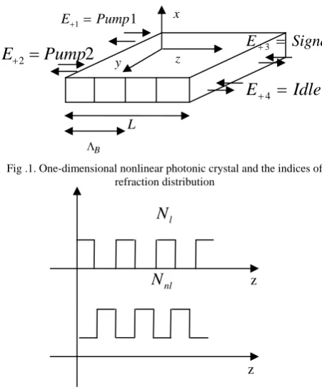
[image:2.595.53.279.154.429.2]We now present a mathematical model for FWM process in 1D nonlinear photonic crystal. Schematic sketch of this structure for modeling FWM process is illustrated in Fig.1.
Fig .1. One-dimensional nonlinear photonic crystal and the indices of refraction distribution
l
N
N
nl zz
Fig.2. Profiles of linear and nonlinear refractive indices
For the proposed structure the refractive index profile is given as follows:
,
)
2
cos(
)
2
cos(
02 2 0
1
0
a
k
z
a
E
k
z
n
n
=
+
+
δ
−
+
δ
(1)where
n
0 ,a
1 ,k
0 ,δ
,a
2 andE
are the average refractive indexes of crystal, the first harmonic coefficient of Fourier expansion for the linear index of refraction, average incident wave vector, detuning between incident wave vector and periodic structure's wave vector, the first harmonic coefficient of Fourier expansion for the nonlinear index of refraction and the applied electric field, respectively. Equation. (1) shows that both linear and nonlinear components of the refractive indexes are chosen to be periodic as shown in Fig.2.We have written the following field distribution for FWM process in the periodic structure,
.,
.
)
(
)
(
)
(
)
(
4 4
4 4
4
3 3 3 3
3
2 2
2 2
2
1 1 1 1
1
c
c
e
e
E
e
E
e
e
E
e
E
e
e
E
e
E
e
e
E
e
E
E
t i z ik z
ik
t i z ik z
ik
t i z ik z
ik
t i z ik z
ik
+
+
+
+
+
+
+
+
=
− −
− −
− −
− −
− +
− +
− +
− +
ω ω ω
ω
(2)
where
E
±i,k
i, andω
iare amplitudes of the forward and backward pump , signal and idler fields, their wave vectorsand frequencies for all components, respectively. In writing the electric field distribution, phase mismatch condition between four wave vectors should be satisfied,
4 3 2
1
k
k
k
k
k
=
+
−
−
Δ
(3) whichk
1 ,k
2 ,k
3 andk
4are two pump, signal and idler wave vectors respectively.Nonlinear polarization is [11],
.,
.
]
)
.
)(
(
2
1
)
.
)(
(
[
* *0
A
z
E
E
E
B
z
E
E
E
c
c
P
NL=
ε
i j k+
i j k+
(4)where
A
(
z
)
andB
(
z
)
are nonlinearities related to nonlinear medium distribution profiles or kerr effect description in our model, and given as follows,], [
) ( )
(z B z Aei(2k0 )z e i(2k0 )z
A = =− +δ + − +δ (5)
where
4
4 3 2 1 0
k k k k
k = + + + . (6) and δ is the detuning of the wave vector of periodic
structure ( ΛB ) with average applied fields' wave vectors(k0).
Indeed, for a wave vector of k0 ,when δ is zero, the photonic crystal works in the center of the forbidden gap so that light does not penetrate into the structure, which is determinable for energy transfer in the WDM (Wavelength Division Multiplexing),the most interesting case occurs when the frequency
ω
0(related tok0) lies at the band edge,which enhances the effective optical nonlinearity and consequently the FWM efficiency.
Now, for obtaining the coupled wave equations, the electric filed and the nonlinear polarization should satisfy the Maxwell's wave equation,
2 2
0 2
2
2 2
2 2
t
P
t
E
c
n
z
E
NL∂
∂
=
∂
∂
−
∂
∂
μ
(7) where
c
is speed of light in vacuum andn
is the refractive index of medium.Because of small perturbation in the refractive index, the following approximation is used in Maxwell's wave equation, that is the coefficients such as
a
1a
2are neglected.2 ) 2 ( )
2 ( 2 0
) 2 ( )
2 ( 1 0 2 0 2
)
(
)
(
0 0
0 0
E
e
e
a
n
e
e
a
n
n
n
z k i z k i
z k i z k i
δ δ
δ δ
+ − +
+ − +
+
−
+
+
=
(8)
Finally, by substituting equations (2), (4) and (8) into Eq. (7) and using the slowly varying function approximation and doing some mathematical simplifications for example all the
sentences having the term
exp(
i
(
ω
1+
ω
2+
ω
3))
t
exp(
i
δ
z
)
are neglected,because they can not oscillate and couple inside the crystal, so the following coupled wave equations are obtained, Signal
E+3 =
Idler
E
+4=
11 Pump E+ =
2
2
Pump
E
+=
x
z
y
L
[image:2.595.54.288.156.258.2]],
2
[
)
4
3
(
2
2 * 4 * 3 1 3 1 2 1 1 2 1 2 0 2 1 2 1 1 0 2 1 1 1 kz i z i z i z i z i z ie
e
E
E
E
e
E
e
E
e
E
c
k
A
a
n
i
c
k
e
E
a
n
i
z
E
Δ + − − − + + −+
+
+
×
+
−
=
∂
∂
+ − δ δ δ δ δα
α
α
ω
ω
(9) where.
2
2
2
,
2
2
2
,
2
2
2
2
2
2
2
* 4 4 * 3 3 * 2 2 * 1 1 3 * 2 2 * 4 4 * 3 3 2 2 4 2 3 2 2 2 1 2 4 2 3 2 2 2 1 1 + − + − − + − + + − − + − + − − − − + + + ++
+
+
=
+
+
=
+
+
+
+
+
+
+
=
E
E
E
E
E
E
E
E
E
E
E
E
E
E
E
E
E
E
E
E
E
E
α
α
α
(10)Equation. (9) illustrates the coupled wave equation for the first pump field propagating from left to right inside the crystal.
],
2
[
)
4
3
(
2
* 2 4 3 1 3 1 2 1 1 2 1 2 0 2 1 2 1 1 1 0 2 1 1 kz i z i z i z i z i z ie
e
E
E
E
e
E
e
E
e
E
c
k
A
a
n
i
c
k
e
E
a
n
i
z
E
Δ − − + − − − − − − + − + −+
Γ
+
Γ
+
Γ
×
+
−
=
∂
∂
−
δ δ δ δ δω
ω
(11) where.
2
2
2
,
2
2
2
,
2
2
2
2
2
2
2
* 4 4 * 3 3 * 2 2 * 1 1 3 * 4 4 * 3 3 * 2 2 2 2 4 2 3 2 2 2 1 2 4 2 3 2 2 2 1 1 − + − + + − + − + − + − − + − − − − + + + ++
+
+
=
Γ
+
+
=
Γ
+
+
+
+
+
+
+
=
Γ
E
E
E
E
E
E
E
E
E
E
E
E
E
E
E
E
E
E
E
E
E
E
(12)Equation. (11) illustrates the coupled wave equation for the backward component of the first pump field propagating from right to left inside the crystal.
We have the similar equation forms for the co-propagation fields-
E
+2 ,E
+3 ,E
+4 ,E
−2 ,E
−3 ,E
−4 which can be obtained straight forwardly.We have solved these equations numerically and the effect of system parameters on conversion efficiency (For each one of pump photons which are annihilated, signal and idler photons are created correlately) is considered and illustrated in the next section. The conversion efficiency for forward traveling signal components can be defined as follows,
, ) 0 ( ) 0 ( 1 3 + + + = P P
η (13) We will call this efficiency co-propagation efficiency in the next sections. P+3(0) and P+1(0) stands for the forward pump and signal power respectively, which signal and pump fields are applied from right hand side and left hand side to our system respectively. Also, we define conversion efficiency parameter for the backward signal power as follows, , ) 0 ( ) ( 1 3 + − − = P L P
η (14) where P−3(L) is the backward signal power at the right hand side of crystal.
III. SIMULATION RESULTS AND DISCUSSION
In this section we present some of numerical results for both co-propagating and counter-propagating efficiencies in FWM process.
Our simulations show that the co-propagating efficiency is larger than the counter-propagating efficiency; this is due to the basic principles of energy transfer between forward and backward propagating modes in Brag gratings.
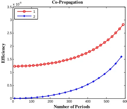
Figure. (3) shows the effect of number of periods on co-propagation conversion efficiency. Conversion efficiency is decreased by decreasing of the nonlinear refractive index coefficient.
As it is shown in Fig. (3), we have increased the layers f crystal up to 600 layers, in simulation process we observed that by choosing the number of layers to more than 600 layers, co-propagating efficiency has oscillatory behavior, so it is necessary to keep in mind that the conversion efficiency is nonlinearly dependant on the number of periods and this subject should be considered in design process of a photonic crystal to avoid decreasing of the conversion efficiency.
0 100 200 300 400 500 600
1.2 1.4 1.6 1.8 2 2.2 2.4 2.6 2.8
3x 10
-8 E fficie n cy Co-Propagation
Number of periods
[image:3.595.47.288.54.244.2]1 2 3
Fig. 3. Efficiency vs. number of periods for different values of a2
) ( 0 , 001 . 0 ), ( 0 , 45 . 3 , 10 3 ) 3 , 10 2 ) 2 , 10 )
1a2=− −15 a2=− × −15 a2=− × −15n0= Δk= m−1 a1= δ= m−1
Figure. (4) illustrates the effect of phase mismatch between wave vectors of four optical fields (two pumps, signal and idler fields) on conversion efficiency. It is shown that by increasing of phase mismatch, the conversion efficiency is decreased, due to the weak energy transfer between propagating modes inside the crystal.
0 100 200 300 400 500 600
0 0.5 1 1.5 2 2.5 3 3.5x 10
-8 E ff ic ien cy Co-Propagation
Number of Periods 1
2
[image:3.595.47.289.284.435.2] [image:3.595.317.526.287.442.2] [image:3.595.325.536.569.750.2]001 . 0 ), ( 0 , 45 . 3 , 10 )
3
), ( 001 . 0 ) 2 ), ( 0001 . 0 ) 1
1 1 0
15 2
1 0 1
0
= =
= −
=
= Δ =
Δ
− −
− −
a m n
a
m k k
m k k
δ
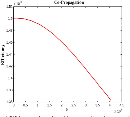
Figures. (5) and (6) demonstrate the effect of phase mismatch between the average wave vector of optical fields and Grating wave vector on the conversion efficiency, as
δ
increases the conversion efficiency decreases. So in order to obtain high efficiencies in Bragg gratings,δ
should be considered as small as possible. Also careful choice of number of layers is important due to the nonlinear dependence between number of layers and the conversion efficiency as discussed before.0 100 200 300 400 500 600
1.2 1.4 1.6 1.8 2 2.2 2.4 2.6 2.8
3x 10
-8
E
ff
ici
en
c
y
Co-Propagation
Number of Periods 1
[image:4.595.315.529.468.650.2]2 3
Fig. 5. Efficiency vs. number of periods for different values of
δ
15 2 1
1 0
1 0 1
0 1
0
10 , 001 . 0 ), ( 0 , 45 . 3
), ( 003 . 0 ) 3 ), ( 002 . 0 ) 2 ), ( 001 . 0 ) 1
− −
− −
−
− = =
= Δ =
= =
=
a a
m k n
m k m
k m
k δ δ
δ
The effect of phase mismatch between Grating wave vector and the average wave vector of four optical fields on conversion efficiency in broad ranges is shown in Fig. 6 .It is apparent that the higher
δ
is, the smaller the efficiency.0 0.5 1 1.5 2 2.5 3 3.5 4 4.5
x 104 1.36
1.38 1.4 1.42 1.44 1.46 1.48 1.5 1.52x 10
-8
E
ff
ici
en
cy
Co-Propagation
[image:4.595.55.279.534.734.2]δ
Fig. 6. Efficiency vs. phase mismatch between grating and average applied fields' wave vectors.
300 , 10 , 001 . 0 ), ( 0 , 45 .
3 1 1 2 15
0= Δk= m− a = a =− − N=
n
The same simulations have been illustrated for counter-propagation case.
Figures .(7) and (8) show the effect of phase mismatch between the average wave vectors of the optical fields and grating wave vector on the conversion efficiency, and as it is expected, by increasing δ ,the counter-propagating efficiency decreases.
0 100 200 300 400 500 600
0 0.2 0.4 0.6 0.8 1 1.2 1.4 1.6x 10
-8
E
ff
ici
en
cy
Counter-Propagation
Number of Periods 1
2 3
Fig. 7. Efficiency vs. number of periods for different values of
δ
15 2 1
1 0
1 0 1
0 1
10 ,
001 . 0 ), ( 0 , 45 . 3
), ( 01 . 0 ) 3 ), ( 001 . 0 ) 2 ), ( 0 ) 1
− −
− −
−
− = =
= Δ =
= =
=
a a
m k n
m k m
k
m
δ
δ
δ
We observed the same results from our simulations for counter-propagating fields. As an example, we show the nonlinear refractive index's coefficient in different number of layers, on the counter-propagation conversion efficiency.
0 100 200 300 400 500 600
0 0.2 0.4 0.6 0.8 1 1.2 1.4 1.6x 10
-8
E
ff
ic
ien
cy
Counter-Propagation
Number of Periods 1
2 3
Fig. 9. Efficiency vs. number of periods for different values of
a
2) ( 0 , 001 . 0 ), ( 0 , 45 . 3
, 10 3 ) 3 , 10 2 ) 2 , 10 )
1
1 1
1 0
15 2
15 2
15 2
− −
− −
−
= =
= Δ =
× − = ×
− = −
=
m a
m k n
a a
a
δ
IV. SUMMARY AND CONCLUSION
process have been derived and numerical results for the steady state study have been discussed. We have considered the Bragg as a lossless and inhomogeneous medium. The linear and nonlinear refractive indices are considered to be periodic.
It has been shown that although we have considered that all the fields deplete via propagating in 1D photonic crystal-which specially becomes important when the number of layers increase - and we have used a medium with
χ
(3) nonlinearity, an enhancement of at least 100 times in both co-propagating and counter-propagating efficiencies have been observed compared to the previous works that use undepleted pump fields andχ
(2) medium [12].In summary, NCMEs are derived via 1D nonlinear photonic crystal using the following cases:
1. We have used continuous wave frequency rather than short pulse case.
2. All fields (pump, signal and idler fields) are affected by Bragg grating, so both SPM (Self-phase
modulation) and XPM (Cross-phase modulation) phenomena are observed in Eqs.( 9)-(11) and similar equations for
2 +
E
,E
+3,E
+4,E
−2,E
−3,E
−4 .3. Pump depletion have been considered, although this is not necessarily serious because of low conversion efficiencies but it affects the efficiency especially in large number of layers.
4. Both linear and nonlinear refractive of indices are periodic.
5. In simulation processes both backward and forward components of the fields are taken into account and none of them are neglected.
ACKNOWLEDGMENT
The author would like to express her senior thanks to Prof.Mir Kamal Mirnia from the Mathematics department at the University of Tabriz for the useful and fruitful discussions on numerical solving methods of nonlinear coupled equations.
REFERENCES
[1] M. J. Steel and C. Martijn de Sterke, "Parametric amplification of short
pulses in optical fiber Bragg gratings", Phys. Rev. E, Vol.
54,4271,1996.
[2] M. J. Steel and C. Martijn de Sterke, "Continuous-wave parametric
amplification in Bragg gratings", JOSA B, Vol 12, 2445 ,1995.
[3] G. P. Agrawal, Nonlinear Fiber Optics ,3rd Ed., Academic Press, New
York, 2001.
[4] H. Takesue, K. Inoue, "Generation of polarization entangled photon
pairs and violation of Bell's inequality using spontaneous four-wave
mixing in fiber loop". Arxiv:quant-ph/0408032 V1.
[5] B. Sanders, J. Vuckoric and P. Grangier, "Single photons on demand",
Europhysics news, March 2005.
[6] M. C. Booth, M. Atature, G. Di Giuseppe, B. E. A. Saleh, A. V.
Sergienko and M. C. Teich, "Counter-propagating Entangled Photons
from a Waveguide with Periodic Nonlinearity", Phys. Rev. A, Vol. 66,
023815, 2002.
[7] L. J. Wang, C. K. Hong and S. R. Friberg, "Generation of Correlated
Photons via Four-wave Mixing in Optical Fibers", J. Opt. B: Quantum
Semiclass. Opt. 3, 346-352 , 2001.
[8] W. T. M. Irvin, M. J. A. de Dood and D. Bouwmeester, "Bloch Theory
of Entangled Photon Generation in Nonlinear Photonic Crystals", Phys.
Rev. A, Vol. 72, 043815, 2005.
[9] D. Petrosyan and G. Kurizki, "Photon-photon Correlations and
Entanglement in Doped Photonic Crystals", Phy. Rev. A, Vol. 64,
023810, 2001.
[10] A. Yarive, Quantum Electronics, 3rd Ed., John Wiley, New York, 1989.
[11] R. W. Boyd, Nonlinear Optics ,Boston, Academic Press, 1992.
[12] A. N. Vamivakas, B. E. A. Saleh, A. V. Sergienko, and M. C. Teich,
"Theory of Spontaneous Parametric Down-conversion from Photonic
Crystals", Phys. Rev. A, Vol. 70, 043810, 2004.
[13] S, John, "Strong Localization of Photons in Certain Disordered
Dielectric Superlattices" , Phys. Rev. Lett, Vol. 58, 2486, (1987).
[14] E. Yablonovitch, "Inhibited Spontaneous Emission in solid-state
Physics and Electronics", Phys. Rev. Lett., Vol. 58,pp.2059-2062,